Posts with «arduino» label

KeyMouSerial Solves Your Raspberry Pi Keyboard Problems

All laptops have a working keyboard and mouse built into them, the only problem is that you can’t use these tools on other computers that don’t have them. At least, until now. [Peter] has created the KeyMouSerial in order to use his laptop’s keyboard and mouse as physical devices on his Raspberry Pi, finally freeing the bonds holding our laptops’ human interface devices back.

The software for KeyMouSerial copies keystroke and mouse information and sends this out via a serial port on his laptop (using a USB to serial adapter). From there the information is translated by an Arduino into HID commands which are sent via USB to the target computer, in this case a Raspberry Pi. It’s a pretty elegant solution to carrying a bulky keyboard and mouse along just for a Raspberry Pi, or for any computer that might not have access to a network and SSH.

[Peter] has also been working on using his iPod as a serial-to-USB converter, so if you’re a Rockbox developer and want to help out then drop him a line. All of the software is available (for Windows, Mac, or Linux) including the Arduino sketch if you want to try this software out for yourself. And, if you don’t want to turn a computer into a keyboard and want to go the other direction and turn a keyboard into a computer, that is also an option.


Filed under: laptops hacks

Art Drops: capturing what the human eye can’t see


Art Drop is a project by italian photographer Gianluca Sambo and recently awarded with first prize from PX3, “Prix de la Photographie de Paris”. He’s been experimenting for some time a DIY technique based on Arduino to capture amazing shapes of liquid drops mixed with dyes and other ingredients to vary the density, and therefore, the shape of the liquid in motion. Arduino allows him to synchronise the camera with the flash and the water pump, creating a series of pictures full of colours and unforeseen shapes.

Take a look at the video below to see how it works:

Arduino Blog 25 Jun 23:22

Embed with Elliot: I2C Bus Scanning

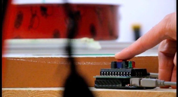
A lot of great ICs use I2C to communicate, but debugging a non-working I2C setup can be opaque, especially if you’re just getting started with the protocol/bus. An I2C bus scanner can be a helpful first step in debugging an I2C system. Are all the devices that I think should be present actually there and responding? Do they all work at the bus speed that I’m trying to run? If you’ve got an Arduino or Bus Pirate sitting around, you’re only seconds away from scanning your I2C bus, and answering these questions.

The Lowdown: I2C in Brief

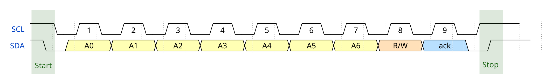
I2C is a two-wire (plus ground) communications bus and protocol. The physical layer is just two signal wires: a clock line (SCL) that’s controlled by the master, and a data line (SDA) that can be controlled by either the master or the addressed slave unit. Data is always read on the SDA line when the clock is high, and a new value is established while the clock is low. The two exceptions to this rule are the stop and start signals, where the master is allowed to raise and drop the data line while the clock is still high. Because this change shouldn’t ever happen during data transfer, the stop and start signals are easy to detect.

All data is sent in eight-bit packets and each packet is acknowledged by the recipient, whether master or slave. To start up a conversation, the master sends the start signal and then the seven-bit address of the slave device that it wants to speak to. The eighth bit in the master’s first packet tells the slave whether the master is going to transmit more data (a “write” command, a zero) or whether the master is requesting data back from the slave (a “read” value, a one).

After the eight bits are sent, the slave is required to acknowledge receipt by pulling the data line low.  This acknowledge signal is exactly what the I2C bus scanning software will need to look for in order to detect a chip with the given address on the bus.

There are, of course, a lot more complicating details to I2C. For instance, there are a whole range of permissible clock speeds at which the transmissions can take place: ranging from the default 100kHz data rate, through 400kHz “fast mode”, 1MHz “fast mode plus”, and up as far as 5MHz “ultra-fast mode”. (We await the 10MHz “super-duper, really-really-fast mode” with baited breath.) And since the bus is clocked by the SCL line, almost any slower data rate up to the maximum allowed will work just fine.

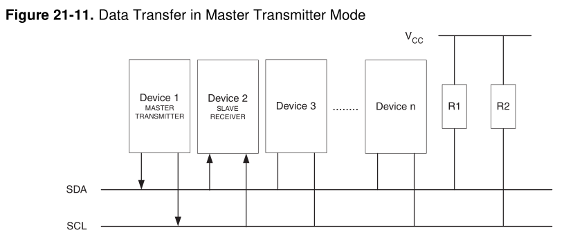
The physical lines are pulled up to a logic-high voltage level by pullup resistors, and the devices signal low by pulling the line down. This means that the voltage transitions can be a little blurry, especially on long runs or other situations where the line itself capacitively couples to the circuit. These physical factors will play a role in determining how fast you can send signals on the I2C bus, and you may need to fine-tune the pullup resistors in your particular system.

There are a surprisingly large number of other ways that things can go wrong on an I2C bus, so it’s great to be able to start debugging at the very beginning — is the slave even getting my first (address) packet at the speed I’m sending? Hence the utility of an I2C scanner.

A Scanner

A first cut at an I2C bus scanner, then, can be made by just cycling through all 127 possible slave device addresses, and checking whether or not they acknowledge. Next, you might want to re-run the same test at a bunch of different bus speeds, if you thought that you might be having troubles with signal rise- and fall-times. Finally, and we’ve never seen this implemented, it might be cool to have a database of common I2C slave device addresses so that the scanner itself can report back which particular chips it’s found.
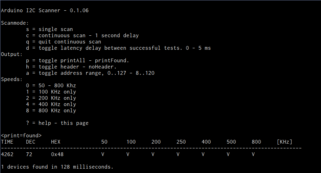
For the Arduino, the most featureful scanner we’ve seen is posted on the Arduino forums, with the code hosted on Github, in the “sketches/MultiSpeedI2CScanner” folder.  It actually does everything that we’d want in a simple scanner: scans the entire bus at different speeds and plots the results out nicely over the serial port for perusal on your computer. It’s configured to do a full scan on reboot. Type “ps” to print only the found devices and start a scan. Bam!

The one caveat with the Arduino scanner is that if you’ve neglected to connect pullup resistors on the SDA and SCL lines (we would never!) the scanner seems to hang somewhere when running at 800kHz. We suspect it’s waiting to become bus master and just gets stuck; we wonder why there’s not a timeout in the twi_writeTo() function in the Arduino “twi.c” library. (Anyone have a good guess?) Other speed modes worked just fine, and everything was peachy again after adding a 10k pullup resistor to SDA.

Naturally, the Bus Pirate (the swiss-army knife of serial communications) will do an I2C scan. It only runs one frequency at a time, but it’s quick enough that you can step through them all in short order. It’s got a quirk, or maybe a feature; it treats the read/write bit as part of the address, so it will test each chip in both directions. Enter the I2C mode, set the desired speed and pullup/power options, and finally type “(1)” for option 1: 7-bit address search. You should see all the devices that responded on the bus listed out for you.

Writing your own code to do a scan is surprisingly simple as well, if you know the chips you’re working with. Most microcontrollers’ dedicated hardware I2C interfaces will report error codes in a specific register. If you can figure out how to test for the “didn’t acknowledge after sending the address and data-direction packet” error, the code pretty much writes itself.

Going Further

Once you’ve got the basics verified — the slave responds when addressed at the desired speed — and your I2C setup still isn’t working, you’re on to debugging the harder problems. There are other tests you might like to do, but unfortunately they all run quickly into the slave-device specific command sets. For instance, many devices will receive a command to reply with a known device ID, or the contents of a default register, or similar. These are useful to make certain that you’ve got multi-byte commands working as expected.

If you suspect that you’re having problems with the signals not rising or falling fast enough, perhaps because you’ve seen chips respond at low speeds but not at higher ones during the scan above, you’re going to need an oscilloscope to actually probe out the analog voltages on the lines. Or try lower-value pullup resistors to speed up the rising edges and test again.

Harder to catch or infrequently occurring glitches on a multi-master I2C bus get really hard to track down really fast. But getting the simple stuff verified working first — all parts are on the addresses that you think they are — can get you set on the right path.

Good luck with your I2C projects! And if you’ve got any other useful I2C debugging tools or strategies up your sleeves, feel free to discuss in the comments.


Filed under: Hackaday Columns, Microcontrollers, peripherals hacks

Watch Makezine’s interview with Massimo Banzi and Eric Pan

According to Make, the biggest news coming out of Maker Faire Shenzhen, outside the size and intensity of the event itself, was the partnership involving our team at Arduino and SeeedStudio.  Massimo Banzi during his talk presented Arduino boards using the new sister brand Genuino which will be made in China by Seeedstudio.

Dale Dougherty was in Shenzhen with them and did this video interview and article:

Motion Sensing Water Gun Tweets Photos To Embarrass Enemies

[Ashish] is bringing office warfare to the next level with a motion sensing water gun. Not only does this water gun automatically fire when it detects motion, but it also takes a photo of the victim and publishes it on Twitter.

This hack began with the watergun. [Ashish] used a Super Soaker Thunderstorm motorized water gun. He pulled the case apart and cut one of the battery wires. he then lengthened the exposed ends and ran them out of the gun to his control circuit. He also placed a protection diode to help prevent any reverse EMF from damaging his more sensitive electronics. The new control wires run to a MOSFET on a bread board.

[Ashish] is using a Lightblue Bean board as a microcontroller. The Bean is Arduino compatible and can be programmed via low energy Bluetooth. The Bean uses an external PIR sensor to detect motion in the room. When it senses the motion, it activates the MOSFET which then turns on the water gun.

[Ashish] decided to use Node-RED and Python to link the Bean to a Twitter account. The system runs on a computer and monitor’s the Bean’s serial output. If it detects the proper command, it launches a Python script which takes a photo using a webcam. A second script will upload that photo to a Twitter account. The Node-RED server can also monitor the Twitter account for incoming direct messages. If it detects a message with the correct password, it can use the rest of the message as a command to enable or disable the gun.


Filed under: Arduino Hacks

Smile! This plant wants to take a selfie with you

Selfie Plant is an interactive installation taking pictures of itself using Arduino Yún, Facebook Graph APIs and then uploads them to Facebook. It was developed by a group of students at the Copenhagen Institute of Interaction Design during “The secret life of objects” course held also by Arduino.cc team. The final prototype was placed in the exhibition of the school, to see the interaction of the audience with it and you can see the result on Facebook.

The Selfie Plant is an attempt to provoke some thoughts above genre of expression. The Selfie Plant expresses itself in the form of nice-looking selfies, which it clicks according to its mood, weather or occasion. It mimics human behaviour, by giving it’s best pose and adjusting the camera angle to take the perfect selfie.


In the documentation on Github you can find all the details of the project composed by an Arduino Yún, controlling 2 servo motors and adjusting the positions of the plant and the camera stick; a python script (facebook.py) which communicates with Facebook’s graph API to post the captured photos on plant’s Facebook profile. In addition you’ll need also a LED Matrix, a Bread Board and 5 Volt Battery.

Here’s a preview of the diagram:


Smile! This plant wants to take a selfie with you

The Selfie Plant is an interactive installation taking pictures of itself using Arduino Yún, Facebook Graph APIs and then uploads them to Facebook. It was developed by a group of students at the Copenhagen Institute of Interaction Design during “The secret life of objects” course held also by Arduino.cc team by Joshua Noble and Simone Rebaudengo. The final prototype was on display at the class exhibition, to observe the interaction of the audience with it, and the results are on Facebook.

The Selfie Plant is an attempt to provoke some thoughts above genre of expression. The Selfie Plant expresses itself in the form of nice-looking selfies, which it clicks according to its mood, weather or occasion. It mimics human behaviour, by giving it’s best pose and adjusting the camera angle to take the perfect selfie.

In the documentation on Github you can find all the details of the project composed by an Arduino Yún, controlling 2 servo motors and adjusting the positions of the plant and the camera stick; a python script (facebook.py) which communicates with Facebook’s graph API to post the captured photos on plant’s Facebook profile. In addition you’ll need also a LED Matrix, a Bread Board and 5 Volt Battery.

Here’s a preview of the diagram:


Arduino Wars: Genuino vs the Phantom Arduino and the Clones

The biggest news coming out of Maker Faire Shenzhen, outside the size and intensity of the event itself, was the announcement made by Massimo Banzi that Arduino boards using the name Genuino will be made in China by Seeed Studio. There have been plenty of Arduino clones made in China that closely […]

Read more on MAKE

The post Arduino Wars: Genuino vs the Phantom Arduino and the Clones appeared first on Make: DIY Projects, How-Tos, Electronics, Crafts and Ideas for Makers.

New Project: How to Make a Robotic Drum Using Arduino

Everyone has a Maker in them. We make for fun and exploration, we make to test ideas, and we make to solve real-world problems. Ponytrap wasn’t intended to be a Maker band — we just seemed to have a difficult time finding a drummer that wanted to play the classically-inspired tribal rhythm industrial music that […]

Read more on MAKE

The post How to Make a Robotic Drum Using Arduino appeared first on Make: DIY Projects, How-Tos, Electronics, Crafts and Ideas for Makers.

Send HEX values to Arduino

FIVE MINUTE TUTORIAL

Project Description: Sending Hex values to an Arduino UNO


This simple tutorial will show you how to send Hexadecimal values from a computer to an Arduino Uno. The "Processing" programming language will be used to send the HEX values from the computer when a mouse button is pressed. The Arduino will use these values to adjust the brightness of an LED.


Learning Objectives


  • To Send Hexadecimal (Hex) values from a computer to the Arduino
  • Trigger an action based on the press of a mouse button
  • Learn to create a simple Computer to Arduino interface
  • Use Arduino's PWM capabilities to adjust brightness of an LED
  • Learn to use Arduino's analogWrite() function
  • Create a simple LED circuit


Parts Required:


Fritzing Sketch


The diagram below will show you how to connect an LED to Digital Pin 10 on the Arduino.
Don't forget the 330 ohm resistor !


Arduino Sketch


The latest version of Arduino IDE can be downloaded here.
 
  1
2
3
4
5
6
7
8
9
10
11
12
13
14
15
16
17
18
19
20
21
22
23
24
25
26
27
28
29
30
31
/* ==================================================================================================================================================
         Project: 5 min tutorial: Send Hex from computer to Arduino
          Author: Scott C
         Created: 21th June 2015
     Arduino IDE: 1.6.4
         Website: http://arduinobasics.blogspot.com/p/arduino-basics-projects-page.html
     Description: Arduino Sketch used to adjust the brightness of an LED based on the values received
                  on the serial port. The LED needs to be connected to a PWM pin. In this sketch
                  Pin 10 is used, however you could use Pin 3, 5, 6, 9, or 11 - if you are using an Arduino Uno.
===================================================================================================================================================== */

byte byteRead; //Variable used to store the byte received on the Serial Port
int ledPin = 10; //LED is connected to Arduino Pin 10. This pin must be PWM capable.

void setup() {
 Serial.begin(9600); //Initialise Serial communication with the computer
 pinMode(ledPin, OUTPUT); //Set Pin 10 as an Output pin
 byteRead = 0;                   //Initialise the byteRead variable to zero.
}

void loop() {
  if(Serial.available()) {
    byteRead = Serial.read(); //Update the byteRead variable with the Hex value received on the Serial COM port.
  }
  
  analogWrite(ledPin, byteRead); //Use PWM to adjust the brightness of the LED. Brightness is determined by the "byteRead" variable.
}


Processing Sketch


The latest version of the Processing IDE can be downloaded here.
 
  1
2
3
4
5
6
7
8
9
10
11
12
13
14
15
16
17
18
19
20
21
22
23
24
25
26
27
28
29
30
31
32
33
34
35
36
37
38
39
40
41
42
43
/* ==================================================================================================================================================
         Project: 5 min tutorial: Send Hex from computer to Arduino
          Author: Scott C
         Created: 21th June 2015
  Processing IDE: 2.2.1
         Website: http://arduinobasics.blogspot.com/p/arduino-basics-projects-page.html
     Description: Processing Sketch used to send HEX values from computer to Arduino when the mouse is pressed.
                  The alternating values 0xFF and 0x00 are sent to the Arduino Uno to turn an LED on and off.
                  You can send any HEX value from 0x00 to 0xFF. This sketch also shows how to convert Hex strings
                  to Hex numbers.
===================================================================================================================================================== */

import processing.serial.*; //This import statement is required for Serial communication

Serial comPort;                       //comPort is used to write Hex values to the Arduino
boolean toggle = false; //toggle variable is used to control which hex variable to send
String zeroHex = "00"; //This "00" string will be converted to 0x00 and sent to Arduino to turn LED off.
String FFHex = "FF"; //This "FF" string will be converted to 0xFF and sent to Arduino to turn LED on.

void setup(){
    comPort = new Serial(this, Serial.list()[0], 9600); //initialise the COM port for serial communication at a baud rate of 9600.
    delay(2000);                      //this delay allows the com port to initialise properly before initiating any communication.
    background(0); //Start with a black background.
    
}


void draw(){ //the draw() function is necessary for the sketch to compile
    //do nothing here //even though it does nothing.
}


void mousePressed(){ //This function is called when the mouse is pressed within the Processing window.
  toggle = ! toggle;                   //The toggle variable will change back and forth between "true" and "false"
  if(toggle){ //If the toggle variable is TRUE, then send 0xFF to the Arduino
     comPort.write(unhex(FFHex)); //The unhex() function converts the "FF" string to 0xFF
     background(0,0,255); //Change the background colour to blue as a visual indication of a button press.
  } else {
    comPort.write(unhex(zeroHex)); //If the toggle variable is FALSE, then send 0x00 to the Arduino
    background(0); //Change the background colour to black as a visual indication of a button press.
  }
}


The Video


The tutorial above is a quick demonstration of how to convert Hex strings on your computer and send them to an Arduino. The Arduino can use the values to change the brightness of an LED as shown in this tutorial, however you could use it to modify the speed of a motor, or to pass on commands to another module. Hopefully this short tutorial will help you with your project. Please let me know how it helped you in the comments below.


If you like this page, please do me a favour and show your appreciation :

 
Visit my ArduinoBasics Google + page.
Follow me on Twitter by looking for ScottC @ArduinoBasics.
I can also be found on Pinterest and Instagram.
Have a look at my videos on my YouTube channel.


However, if you do not have a google profile...
Feel free to share this page with your friends in any way you see fit.