Posts with «accelerometer» label

Controlling a Quadcopter with Gestures

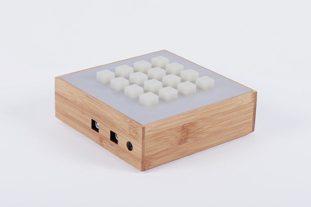
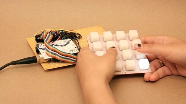
[grassjelly] has been hard at work building a wearable device that uses gestures to control quadcopter motion. The goal of the project is to design a controller that allows the user to intuitively control the motion of a quadcopter. Based on the demonstration video below, we’d say they hit the nail on the head. The controller runs off an Arduino Pro Mini-5v powered by two small coin cell batteries. It contains an accelerometer and an ultrasonic distance sensor.

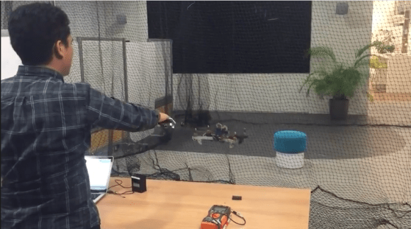
The controller allows the quadcopter to mimic the orientation of the user’s hand. The user holds their hand out in front of them, parallel to the floor. When the hand is tilted in any direction, the quadcopter copies the motion and will tilt the same way. The amount of pitch and roll is limited by software, likely preventing the user from over-correcting and crashing the machine. The user can also raise or lower their hand to control the altitude of the copter.

[grassjelly] has made all of the code and schematics available via github.


Filed under: Arduino Hacks, drone hacks

Sugarcube, a grid based music controller with accelerometer


Once again Amanda Ghassaei sent a cool project she’s been working on lately as an extension of the work she’s been doing on the monome project. Sugarcube is an open source, grid-based, standalone MIDI instrument  self-contained and relatively cheap to make. It communicates via a MIDI output with other electronic MIDI instruments and software environments like Ableton and MaxMSP.

An Arduino Uno generates all of its MIDI data and drives LEDS, buttons, a 2 axis gyroscope, a 3 axis accelerometer,  two potentiometers, and the whole device is powered by a lithium-polymer battery making it pretty portable.

She published detailed  documentation on Instructables to make one yourself   and shared a bunch of videos to discover its main features:

Basically this project is:

A portable, Arduino-powered, grid-based MIDI controller that boots up into a variety of apps to do lots of things with sound. The controller has 16 backlit buttons, used as both inputs and outputs to give the controller some visual feedback. 2 potentiometers give analog control, depending on the app the pots are assigned to tempo, MIDI velocity, pitch, and scrolling (making the avaible grid space larger than 4×4). An x/y accelerometer and an x/y gyroscope add some playful, gestural control to the device; most of the apps implement a “shake to erase” control and several respond to tilt in various ways.

It boots up into 7 different apps, though it has the potential to boot up into 16 total. This device is primarily a MIDI controller, but I’ve also written an app that allows you to pull the button and analog data into MaxMSP and to control audio.

With this project, I was interested in making a device that was a little more self-contained and relatively cheap to make (lots of buttons = lots of $). In keeping more with the concept of the tenori-on, this controller does all its app processing itself, it does not rely on a computer to process button presses/analog controls into MIDI. This means you can plug it directly into a synth or any device that understands MIDI and you’re good to go, no computer required. It runs off a beefy LiPo battery that keeps it running for days on a charge, so it’s fairly portable as well. In keeping with the monome side of things, it’s totally open source and can be adapted to your particular audio setup/needs. All the Arduino code is up on github, along with a MaxMSP patch that decodes data from the controller into something usable in Max.

Cornell Students Create Virtual Archery Game

Inspired by the bow-and-arrow use in Legend of Zelda games, Cornell students Mohamed Abdellatif and Michael Ross created a Virtual Archery game as their Cornell University ECE 4760 Final Project.

Fantastic programming makes this Arduino gaming device something special

The hardware that went into this Arduino gaming console is just fine. But the coding that produced this game called Twisted SNAKE is beyond compare. [Rodot] has programmed several games for the hardware, which uses an Arduino, 160×168 TFT screen, a 3 axis accelerometer, and two input buttons. If you’re interested, there is a forum thread in which he talks a bit more about the hardware design. But you’re not going to want to pass up either of the two videos embedded after the break.

The first clip shows off a bouncing-ball platforming game. The accelerometer moves the ball back and forth, and the top scrolling level brings more ledges into play. This in itself is a great game. But the Twisted SNAKE game shown off in the second video makes our own ARM-based Snake game look like a 3-year-old programmed it. [Rodot] filled up all of the program memory of the ATmega328 chip to  make this happen. There’s a menu system which allows for color themes and difficulty selection. The game play itself lets the snake travel anywhere it wishes with the tail following behind in graceful curves. Wow!


Filed under: arduino hacks, handhelds hacks

Accelerometer for circuits course?

One of the people that I asked to look over the course notes and give me suggestions suggested another lab that would likely appeal to bioengineers:

another cheap experiment, accelerometers from Sparkfun to measure gait patterns or detect falls.  If really ambitious, you can teach chaos theory here with analyzing chaos levels in gait patterns—they are different for men and women.

I’ve used accelerometers before, both the analog output ADXL335 and the I2C MQA8452Q. The ADXL335 breakout board was from Adafruit Industries, the MQA8452Q from Sparkfun.  Although I personally prefer the I2C interface, since it takes up only 2 Arduino pins, programming is outside the scope of this class.

This lab sounds like fun, and it would be good for the bioengineers to think of accelerometers as cheap sensors that are easily used, rather than as magic that comes in cell phones, I’m not sure how we would get a circuits lab out of this. Even the analog-output accelerometer just needs to have its XYZ pins connected to analog inputs on the Arduino.  Anything interesting you do with the accelerometer is in either the mechanical mounting or in the software analyzing the data, not in electronic circuits.

We have several constraints in selecting labs for this circuits course:

  • Lab must teach something useful to the students.
  • Lab must seem interesting (or at least useful) to bioengineering students.
  • Lab must not be dangerous (either to students or to equipment).
  • Lab must be doable in one 3-hour lab session (we can afford at most 2 labs that are 2-session labs).
  • Lab cannot require students to be able to program computers.
  • Lab cannot require knowledge of electronics beyond what is taught in the course.
  • Lab should support the teaching of traditional linear circuits.
  • Lab should involve student design and not just analysis of existing designs.

The accelerometer lab fails on two points: any design component would have to be software and there is no support for teaching linear circuits in the lab.  That’s too bad, because it is otherwise a cool lab idea.


Filed under: Accelerometer, Circuits course Tagged: accelerometer, Arduino, bioengineering, circuits, course design

3-axis accelerometer motion detector project

Description:
A 3-axis accelerometer sits at the heart of this project to provide a nifty little motion detector. Want to know who is stealing from the cookie jar? Want a simple home intrusion detector? Or to test your partner's driving skills? Then have a look at this:

(Soldering required for this project)


Video:


Parts Required:


Instructions:

  1. Overlay the Seeed Studio Base Shield onto the Freetronics Eleven (or compatible Arduino).
  2. Use a Universal Cable to attach a Seeed Studio Grove Button to Analog Pin 0 on the Base Shield. The socket is located directly above the Freetronics Eleven Power plug, and next to the Reset button on the Base Shield. Please note that Analog Pin 1 is not used by the Grove Button.
  3. Use a universal Cable to attache a Seeed Studio Grove Buzzer to Analog Pin 1 on the Base Shield. This is the socket next to the one used in Step 2.
  4. Solder the female header pins to the Protoboard. Overlay the protoboard onto the Base Shield to create a third layer. I created this layer to tidy up the project and make it a little bit more portable. You could just wire up another breadboard on the side.
  5. Stick a mini-breadboard (4.5cm x 3.5cm) onto the protoboard. This allows you to use the protoboard for other projects.
  6. Solder the male headers to the 3-axis accelerometer, and then place it centrally onto the breadboard.
  7. You need 5 wires to connect:
    • GND on protoboard to GND on accelerometer
    • 5V on protoboard to     VIN on accelerometer
    • Analog Pin 3 on protoboard to X on accelerometer
    • Analog Pin 4 on protoboard to Y on accelerometer
    • Analog Pin 5 on protoboard to Z on accelerometer
  8. Connect digital pin 8 to an LED and 330 ohm resistor on the breadboard,
  9. Use a wire to connect the resistor mentioned above to GND on the protoboard
  10. Connect the USB cable from your computer to the Freetronics Eleven, and upload the Arduino Sketch to the board. 
  11. Disconnect the USB cable, and then power the Freetronics Eleven using a 9V battery and clip.
  12. When you press the button, it will sound 3 warning sounds before it becomes activated.
  13. If it detects a vibration or motion that exceeds the tolerance level, it will alarm. The alarm will continue until you either press the Grove button - which resets and reactivates the device or you can press the Reset button on the Base Shield to Stop monitoring for motion.


Sketch


Freetronics Eleven / Arduino Sketch:

 1
2
3
4
5
6
7
8
9
10
11
12
13
14
15
16
17
18
19
20
21
22
23
24
25
26
27
28
29
30
31
32
33
34
35
36
37
38
39
40
41
42
43
44
45
46
47
48
49
50
51
52
53
54
55
56
57
58
59
60
61
62
63
64
65
66
67
68
69
70
71
72
73
74
75
76
77
78
79
80
81
82
83
84
85
86
87
88
89
90
91
92
93
94
95
96
97
98
99
100
101
102
103
104
105
106
107
108
109
110
111
112
113
114
115
116
117
118
119
120
121
122
123
124
125
126
127
128
129
130
131
132
133
134
135
136
137
138
139
140
141
142
143
144
145
146
147
148
149
150
151
152
153
154
155
156
157
158
159
160
161
162
163
164
165
166
167
168
169
170
171
172
173
174
175
176
177
178
179
180
181
182
183
184
185
186
187
188
189
190
191
192
193
194
195
196
197
198
199
200
201
202
203
204
205
206
207
208
209
210
211
212
213
214
215
216
217
218
219
//Motion Detector Alarm - Written by ScottC on 2/08/2012

//Global Variables and constants
const int buttonPin = A0; // button Pin connected to Analog 0
const int buzzerPin = A1; // buzzer Pin connected to Analog 1


//Accelerometer Pins
const int x = A3; // X pin connected to Analog 3
const int y = A4; // Y pin connected to Analog 4
const int z = A5; // Z pin connected to Analog 5


//Alarm LED
const int ledPin = 8; // LED connected to Digital 8


int tolerance=20; // Sensitivity of the Alarm
boolean calibrated=false; // When accelerometer is calibrated - changes to true
boolean moveDetected=false; // When motion is detected - changes to true


//Accelerometer limits
int xMin; //Minimum x Value
int xMax; //Maximum x Value
int xVal; //Current x Value

int yMin; //Minimum y Value
int yMax; //Maximum y Value
int yVal; //Current y Value

int zMin; //Minimum z Value
int zMax; //Maximum z Value
int zVal; //Current z Value


void setup(){
//Begin Serial communication
Serial.begin(38400);

//Initilise LED Pin
pinMode(ledPin, OUTPUT);

}


void loop(){
// If the button is pressed, initialise and recalibrate the Accelerometer limits.
if(analogRead(buttonPin)>500){
calibrateAccel();
}

// Once the accelerometer is calibrated - check for movement
if(calibrated){
if(checkMotion()){
moveDetected=true;
}
}

// If motion is detected - sound the alarm !
if(moveDetected){
Serial.println("ALARM");
ALARM();
delay(1000);
}

}


//This is the function used to sound the buzzer
void buzz(int reps, int rate){
for(int i=0; i<reps; i++){
analogWrite(buzzerPin,900);
delay(100);
analogWrite(buzzerPin,0);
delay(rate);
}
}


// Function used to calibrate the Accelerometer
void calibrateAccel(){
// reset alarm
moveDetected=false;

//initialise x,y,z variables
xVal = analogRead(x);
xMin = xVal;
xMax = xVal;

yVal = analogRead(y);
yMin = yVal;
yMax = yVal;

zVal = analogRead(z);
zMin = zVal;
zMax = zVal;

// Calibration sequence initialisation sound - 3 seconds before calibration begins
buzz(3,1000);

//calibrate the Accelerometer (should take about 0.5 seconds)
for (int i=0; i<50; i++){
// Calibrate X Values
xVal = analogRead(x);
if(xVal>xMax){
xMax=xVal;
}else if (xVal < xMin){
xMin=xVal;
}

// Calibrate Y Values
yVal = analogRead(y);
if(yVal>yMax){
yMax=yVal;
}else if (yVal < yMin){
yMin=yVal;
}

// Calibrate Z Values
zVal = analogRead(z);
if(zVal>zMax){
zMax=zVal;
}else if (zVal < zMin){
zMin=zVal;
}

//Delay 10msec between readings
delay(10);
}

//End of calibration sequence sound. ARMED.
buzz(3,40);
printValues(); //Only useful when connected to computer- using serial monitor.
calibrated=true;

}


//Function used to detect motion. Tolerance variable adjusts the sensitivity of movement detected.
boolean checkMotion(){
boolean tempB=false;
xVal = analogRead(x);
yVal = analogRead(y);
zVal = analogRead(z);

if(xVal >(xMax+tolerance)||xVal < (xMin-tolerance)){
tempB=true;
Serial.print("X Failed = ");
Serial.println(xVal);
}

if(yVal >(yMax+tolerance)||yVal < (yMin-tolerance)){
tempB=true;
Serial.print("Y Failed = ");
Serial.println(yVal);
}

if(zVal >(zMax+tolerance)||zVal < (zMin-tolerance)){
tempB=true;
Serial.print("Z Failed = ");
Serial.println(zVal);
}

return tempB;
}


// Prints the Sensor limits identified during Accelerometer calibration.
// Prints to the Serial monitor.
void printValues(){
Serial.print("xMin=");
Serial.print(xMin);
Serial.print(", xMax=");
Serial.print(xMax);
Serial.println();

Serial.print("yMin=");
Serial.print(yMin);
Serial.print(", yMax=");
Serial.print(yMax);
Serial.println();

Serial.print("zMin=");
Serial.print(zMin);
Serial.print(", zMax=");
Serial.print(zMax);
Serial.println();

Serial.println("------------------------");
}


//Function used to make the alarm sound, and blink the LED.
void ALARM(){

//don't check for movement until recalibrated again
calibrated=false;

// sound the alarm and blink LED
digitalWrite(ledPin, HIGH);
buzz(4,20);
digitalWrite(ledPin, LOW);
}

Printing and programming a self-balancer

The Hackaday staff isn’t in agreement on 3d printers. Some of us are very enthusiastic, some are indifferent, and some wonder what if they’re as widely useful as the hype makes them sound. But we think [Jason Dorweiler's] self balancing robot is as strong a case as any that 3d printing should be for everyone!

Don’t get us wrong. We love the robot project just for being a cool self-balancer. Seeing the thing stand on its own (video after the break) using an Arduino with accelerometer and gyroscope sensors is pure win. But whenever we see these we always think of all the mechanical fabrication that goes into it. But look at the thing. It’s just printed parts and some wooden dowels! How easy is that?

Sure, sure, you’ve got to have access to the printer, it needs to be well calibrated, and then you’ve got to make the designs to be printed out. But these hurdles are getting easier to overcome every day. After all, there’s no shortage of people to befriend who want nothing more than to show off their Makerbot/RepRap/etc.


Filed under: robots hacks

Space experiments for everyone: the ArduSat project

ArduSat, which stands for “Arduino satellite”, is a recently kickstarted project that aims at developing an open platform usable to emulate space scientists:

Once launched, the ArduSat will be the first open platform allowing the general public to design and run their own space-based applications, games and experiments, steer the onboard cameras to take pictures on-demand, and even broadcast personalized messages back to Earth.

ArduSat will be equipped with several sensors (such as cameras, gyros, accelerometers, GPS and more) packed inside a small cube (the side will be approximately 10 cm long) that can be accessed through a set of Arduinos.

Once in orbit, the ArduSat will be accessible from the ground to flash the required firmware for the experiments and for getting back all the collected information. People interested in performing space experiments will have access to a ground replica of ArduSat explotable to test and debug their code before the actual deployment.

The project is very ambitious, and it is expected that such an open accessible space platform will have a considerable impact on how simple space experiments will be carried out in the forthcoming years, in the case of fundraising success.

You may find the Kickstarter page of the project here.

[Via: Hack A Day and Kickstarter]

Some advances in aerial vehicles: bat-inspired smart wings

Researchers from Centro de Automática y Robótica (Universidad Politécnica de Madrid) and from Brown University carried out a very deep research about the specific behavior of bat flight, whose ultimate goal is to replicate the capabilities of bat’s wings by means of an ad-hoc designed micro aerial vehicle (MAV).

From the home page of the project:

[...] this research is oriented towards the development of a biological inspired bat robot platform, that allows to reproduce the amazing maneuverability of these flying mammals. The highly maneuverability is achieved by reproducing the flapping and morphing capabilities of their wing-skeleton structure. This structure is composed by several joints and a membrane that generates the required lift forces to fly.

To mimmic the muscular system that moves the joints of the wing-bones, Shape Memory Alloys (SMA) NiTi wires are used as artificial-muscles. Several challenges in controlling this SMA-based actuation system are regarded in this research.

A lot of research work has already been carried out (see here for a list of publications) and a bat-like MAV prototype has been designed and implemented to both evaluate and validate the research outcomes. Among the other stuff, the core onboard electronic is made up of an arduino-based board, an IMU, a radio transceiver and a rechargeable LiPo battery.

More details on this project can be found here.

[Via: BaTboT project homepage]

Arduino Blog 06 Jun 13:52

Arduino based Quadrotor on a PCB

There are many Quadrotor Projects out there. But, they require a hobbyist to deal with the Frame Designing (Mechanical), a bit of Microcontroller knowledge as well as dealing with the Motor Control (Power Electronics). You may purchase a commercial Radio and a readymade Kit for flying. But, to Do-It-Yourself, is an achievement in itself.

Here is a picture of a Quadrotor designed by Shane Colton using Arduino Pro mini as its flying brain. Shane is a Ph.D Student at Massachusetts Institute of Technology. On being asked about the Project, he replied:

I heard about Arduino some time in 2007/2008 and have used it for a few projects since then. I built the quadrotor for fun / hobby (not related to research). I wanted to build my own (quadrotor) from scratch because I could integrate all the parts onto a single circuit board, and because I like designing the control system myself.

When he says he build the quad from scratch, he literally did it. Neither did he use any commercially available Radio Control, nor did he use any Electronic Speed Controllers (ESCs). Instead he went for creating his own Brushless DC Motor Controller, that too, on the same PCB which acts as the Quadrotor’s Frame.

He spent a lot of time researching about propellor balancing as well as vibrations in the PCB. Here is a video:

Now, that is called a hobby. In a detailed Instructable, he shows how you too can build a Quadrotor on a PCB. He has a project blog at http://scolton.blogspot.com with documentation on most of his projects.

Enjoy the ride:

Arduino Blog 06 Jun 07:47