Posts with «accelerometer» label

How rough your last mountain bike ride was?

Using an Arduino board with a data logging shield that holds an SD card for storage, an accelerometer on the front fork and some method of recording wheel speed, it’s possible to collect data about your bike ride. Then, when at home, a Python script captures the data dump and graphs it.


Wdm006 also says:

I’m in the process of building an ABS and active suspension system for mountain bikes. The first task after initial modeling and design work was to gather a lot of data for more specific design.

Original post can be read here.

Via:[Hackaday]


Arduino tells you how rough your last mountain bike ride was

If you want to see what kind of abuse you’re causing your body when out on those single-track rides this system is just the thing. It’s an Arduino data logger that [Wdm006] takes along on the rides with him. When he gets back home, a Python scripts captures the data dump and graphs it. It may sound like a neat trick, but he’s got something planned for that information.

The enclosure mounts to the stem of his bike. It houses an Arduino board with a data logging shield of his own design. That shield holds an SD card for storage, and breaks the other pins out as screw terminals. Right now there’s an accelerometer on the front fork, and some method of recording wheel speed. This is the research phase of an anti-lock brake system (ABS) he plans to build for mountain biking. No word on what hardware he’ll use for that, but we can’t wait to see how it comes out.


Filed under: transportation hacks

Pebble ties itself up in Twine: sounds so rustic, couldn't be any less (video)

Take an e-ink smartwatch that's got plenty of willing customers, throw in a WiFi-connected sensor box and well, imagine the possibilities. The founders behind Pebble and Twine hope you are, because they have announced that the pair will be connectable through the latter's web-based interface. This means you'll be able to setup text notifications to your wrist when your laundry's done, when someone's at your door and plenty more mundane real-world tasks. A brief video explains how it should all go down, but try not to get too excited -- pre-orders are sadly sold out.

Continue reading Pebble ties itself up in Twine: sounds so rustic, couldn't be any less (video)

Pebble ties itself up in Twine: sounds so rustic, couldn't be any less (video) originally appeared on Engadget on Fri, 11 May 2012 16:41:00 EST. Please see our terms for use of feeds.

Permalink | Email this | Comments

MAKEmatics – Mathematics for Makers

Makers need to familiarize themselves with the core concepts and the theory involved in creating applications such as Motion Sensing and Face Tracking. As the technology is churning out new hardware day and night, DIYers need to work hard to keep up and always be in touch with the latest technology around them.

-->-->

For example, anyone working with Accelerometers/ Gyroscopes or Inertial Measurement Units needs to understand the theory of Vectors, Force, Gravity and be able to work out complex mathematical problems. They may easily get an Arduino Board and an Accelerometer Breakout or an IMU Board and use a library instead of writing their own code but to truly understand the theory behind it; how the device actually works, is not for the faint of heart.


One such problem is the Face Tracking Application. Unless you know the real theory behind how the Algorithm actually works, you can only wonder about that robot which follows its master. Greg Borenstein had an idea of creating a website dedicated to this issue. Makematics – Math for Makers.


In an introductory post, Greg writes:

” I hope to show that a normal programmer with no special academic training can grapple with these areas of research and find a way in to understanding them. And as I go I aim to create material that will help others do the same. If I can do it, there’s no reason you can’t.”

More and more people should step forward and create or compile a good amount of research data to help fellow makers and DIYers in solving complex mathematical problems.

Fitting a sphere

Today I had to write a program to fit a sphere to a bunch of points that were supposedly near the surface of a sphere, but were noisy and sampled in a very biased way.  Since this is obviously not a new problem, I started out doing web research.  but I didn’t look for fitting a sphere, but for fitting a circle, since that is a simpler related problem.

I found a lot of papers, including several review papers, on how to fit a circle to a bunch of points.  The “obvious” method is to  do a least-squares fit to minimize the distance between the points and the circle, minimizing , where is the radius and is the center of the circle.  Unfortunately, that is a difficult problem to solve, and even numerical methods require a lot of iterations to get decent solutions.  What most people do is to change to a slightly different problem that optimizes a different fitness function.  For example, Kåsa’s method minimizes .

There is a very nice, but very formal, presentation of the methods in a paper by Vaughn Pratt from 1987: Direct Least-Squares Fitting of Algebraic Surfaces.  This paper introduced Pratt’s method, which was later slightly improved to make Taubin’s method. I did not read these original papers (other than skimming Pratt’s paper).  Kåsa’s paper (A curve fitting procedure and its error analysis. IEEE Trans. Inst. Meas. 25: 8–14) does not seem to be available on-line.  The IEEE digital library is missing the whole 1976 year.

I did find a recent paper that does careful error analysis of both the geometric approach and several of the algebraic approaches (including the most popular ones: Kåsa, Pratt, and Taubin):

Ali Al-Sharadqah and Nikolai Chernov
Error analysis for circle fitting algorithms
Electronic Journal of Statistics
Vol. 3 (2009) 886–911 ISSN: 1935-7524 DOI: 10.1214/09-EJS419

This paper shows that Taubin’s method is theoretically superior to Pratt’s which is theoretically superior to Kåsa’s (having less essential bias), and gives a very weak example showing it is also tru empirically.  More interestingly, it also gives a “hyperaccurate” algorithm that has less bias even than Taubin’s method.  I did not read the error analysis, but I did read the description of their Hyper algorithm and the implementations of it that Chernov has on his website.

Since I needed Python code, not Matlab code, and I needed spheres rather than circles, I spent a few hours today reimplementing Chernov’s Hyperfit algorithm.  I noticed that the basis suggested by Pratt for spheres, , was a simple modification of the one used in both Pratt’s paper and Chernov’s paper for circles, .  I decided to generalize to dimensions, and use the Numpy package in Python for all the matrix stuff.  I hope I got the generalization right!

From starting to look for papers until getting the code working was about 6 hours, but I had lunch in there as well, so this felt like pretty speedy development.  I’ve released the code with a Creative Commons Attribution-ShareAlike 3.0 Unported License, and would welcome corrections and improvments to it.

Of course, after all this buildup, you are probably wondering why I needed to fit a sphere to points—that is not a common problem for a bioinformatician to have.  Well, it is for the robotics club, of course.  They’ve been having a lot of trouble with the magnetometer calibration and heading code, so we decided to try doing an external calibration of the magnetometer, which has an enormous arbitrary 3D offset.  By waving the magnetometer around in different orientations (which means tumbling the ROV once the magnetometer is installed), we can sample the magnetic field in many orientations, though far from uniformly.  The center of  the sphere fitted to the readings gives us the 3D offset for the magnetometer.

My son and I tested it out with Python code and Arduino code that he had written to get the data from the magnetometer to the laptop, and the magnetometer readings do seem to be nicely centered around (0,0,0) after we do the correction.  We’re still having trouble using the accelerometer to get a tilt correction to give us clean compass headings, but that is a problem for tomorrow morning, I think.


Tagged: Arduino, circle fitting, magnetometer, NumPy, Python, sphere fitting

Sensor board for underwater ROV

Since I had bought the robotics club an I2C accelerometer and magnetometer, I decided to make a new PC board for them to mount the accelerometer, the magnetometer, and the pressure gauge on the same board.  I don’t have the SMD soldering skills to solder all the chips onto one board, and I already had breakout boards for the accelerometer and magnetometer from Sparkfun, so I decided just to put connectors for those breakout boards onto the back of the pressure sensor board.  (The back, because the pressure sensor on the front has to be stuck through a hole in the dry box and glued in place.

The new boards are tiny (1.05″ × 1.425″), so I decided to try BatchPCB (which has pricing by the square inch) rather than 4pcb.com (which has fixed pricing per board, up to a fairly large size).  The price from BatchPCB was $10 per order plus $2.50/square inch plus $0.90 for shipping, so ordering 3 copies of the board (though I only needed one), cost me $22.12, substantially less than a single board from 4pcb.com, which is $33 plus $17.30 shipping and handling per board (plus an extra $50 if your board has multiple boards on it).  The 4pcb price is lower if your board is bigger than about 15.76 square inches, so even my HexMotor boards (at 12.44 square inches) would be cheaper from BatchPCB.  If you get multiple boards from 4pcb.com on a single panel and cut them apart yourself, the breakeven point is about 35.76 square inches for a single design (so three HexMotor boards from a single 4pcb.com panel is cheaper than from BatchPCB). For multiple designs on a single panel, the 4pcb.com deal is better: for 3 different designs, a total of 27.04 square inches would make 4pcb.com the cheaper way to go.

If you want a copy of the board, you can order it from BatchPCB, or pick up the Eagle files from my web site and order copies from elsewhere.  I’ve put the HexMotor Eagle files on line also, but not put them on the BatchPCB site.  I should probably upload them there sometime.

Bottom line: BatchPCB is better for small numbers of tiny boards, but 4pcb.com is better for larger boards and multiple designs.

The BatchPCB orders came back quite quickly (12 days from order to delivery by mail), though I had been worried because their design-rule check, which they say takes minutes had taken about 8 hours.  The problem was that each check takes a few minutes, but they had hundreds in the queue over the weekend, and it took a full day to clear the queue.

I had less trouble soldering the pressure gauge this time (this was my second attempt at soldering surface mount devices).  You can see in the pictures above that the results are much cleaner than in my first attempt.

The robotics club has tested the pressure sensor on the new board (using their own code on the Arduino) and it seems to work ok,  have drilled the hole in the dry box for the port, and glued the sensor board in place using superglue.  It seems to be waterproof (at least down to 1 foot—we’ve not tested in deep water yet).

Related articles

Tagged: accelerometer, Arduino, BatchPCB, magnetometer, pressure sensor, Printed circuit board, ROV, SparkFun Electronics

MMA7455L Three Axis Digital Output Accelerometer


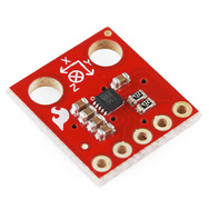
This module integrates the sensor MMA7455L (produced by Freescale), able to detect the movement on three axes, and then in every direction. The chip offers the possibility to select three different sensitivity (± 2g, ± 4g, ± 8g) and makes available, on an SPI bus and the I ² C-Bus, the data detected by allowing a more easily read by a microcontroller. There are also two programmable interrupt lines to communicate a certain event, or to perform one or more actions when it detects a certain acceleration or when the module is stopped.

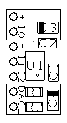
The accelerometer connections are carried out on a male strip pitch 2.54 mm, seven contacts, which allows the insertion in any dip socket, female strip or directly on the printed circuit. The module, powered with a DC voltage of 2.5 to 3.6 V, is suitable for be used in all systems that require the detection of movement, acceleration, such as an alarm systems for vehicle, laboratory analytical instruments, electrical equipment, machinery test and robots.

The module has extremely compact dimensions (10x18x3, 6mm).

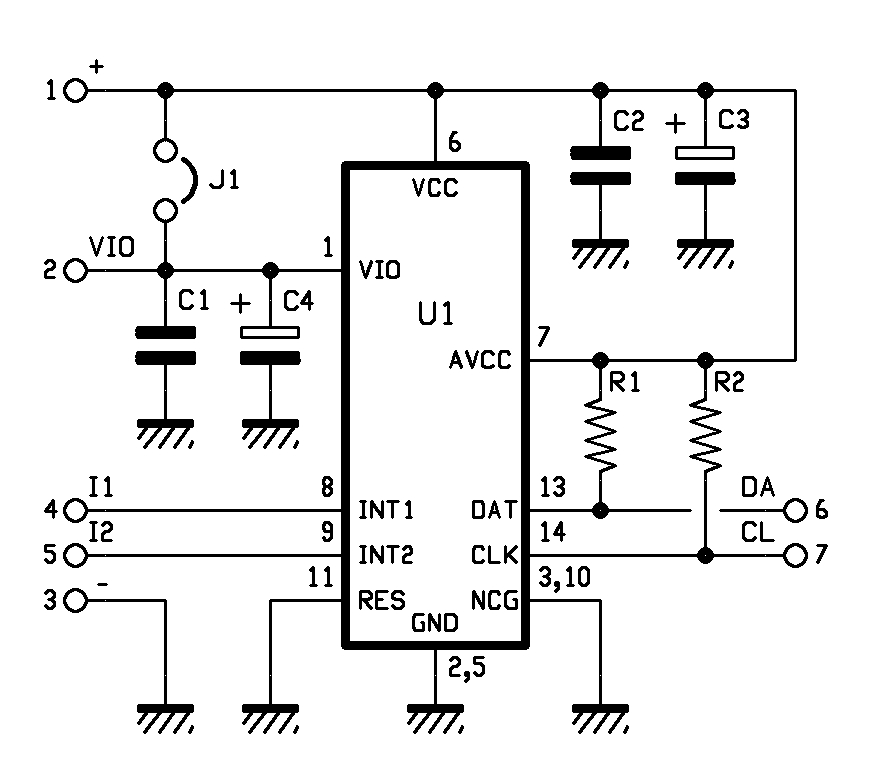
Before using this module is necessary to establish (through jumper J1) which must be the voltage applied to pin VIO (Digital Power for I/O pads), levels of the I / O interface must be the same of micro. If the voltage applied between the pin + and – of the module is the same as the interface device is necessary to close J1, while if it is different (for example because the micro operates at 5V) the jumper must be open and the line VIO must be connects to the same supply voltage of the microcontroller. The I ² C-Bus module is assigned to 00111011. For more information on the chip MMA7455L consult the datasheet from the Internet site www.freescale.com.

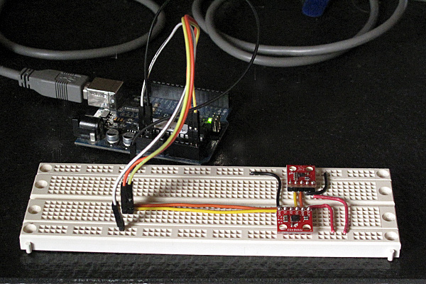
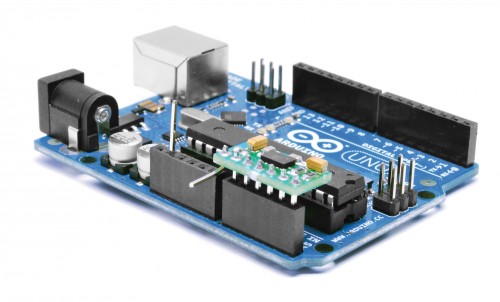
To show the operation of the module I made a little demo with Arduino.

The connection to the microcontroller is very simple and the pin-out allows you to insert the module in the 6-pin for the analog inputs.
The low absorption permit to use the input pin A0 as level of communicationis (VIO) brought it to a high logic level (5V), while the pin A1 is set to 0, the mass for the MMA7455L.
The main supply voltage is provide from 3.3 V by Arduino.

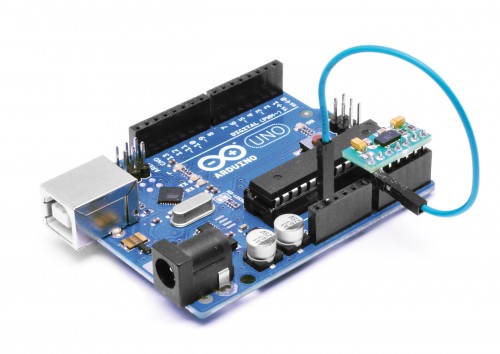
Thanks to the library Wire.h pin A4 and A5 are used to communicate directly with the module.
The communication is very simple thank the library MMA_7455.h developed by Moritz Kemper.

// Example which uses the MMA_7455 library
// Moritz Kemper, IAD Physical Computing Lab
// moritz.kemper@zhdk.ch
// ZHdK, 20/11/2011

//Modified by Boris Landoni
//www.open-electronics.org

#include <Wire.h> //Include the Wire library
#include <MMA_7455.h> //Include the MMA_7455 library

const int vcc =  A0;
const int gnd =  A1; 

MMA_7455 mySensor = MMA_7455(); //Make an instance of MMA_7455

char xVal, yVal, zVal; //Variables for the values from the sensor
float x, y, z;

void setup()
{
  pinMode(gnd, OUTPUT);
  pinMode(vcc, OUTPUT);
  digitalWrite(gnd, LOW);
  digitalWrite(vcc, HIGH);
  delay (1000);

  Serial.begin(9600);
  Serial.println("start");

  // Set the sensitivity you want to use
  // 2 = 2g, 4 = 4g, 8 = 8g
  mySensor.initSensitivity(8);
  // Calibrate the Offset, that values corespond in
  // flat position to: xVal = -30, yVal = -20, zVal = +20
  // !!!Activate this after having the first values read out!!!
  mySensor.calibrateOffset(0, 0, 0);

}

void loop()
{
  long start = micros();
  //xVal = mySensor.readAxis('x'); //Read out the 'x' Axis
  //yVal = mySensor.readAxis('y'); //Read out the 'y' Axis
  //zVal = mySensor.readAxis('z'); //Read out the 'z' Axis
 /* Serial.print("x: ");
  Serial.print(xVal*0.016, 2);
  Serial.print("\t y: ");
  Serial.print(yVal*0.016, 2);
  Serial.print("\t z: ");
  Serial.println(zVal*0.016, 2);

  Serial.print("x: ");
  Serial.print(xVal,DEC);
  Serial.print("\t y: ");
  Serial.print(yVal,DEC);
  Serial.print("\t z: ");
  Serial.print(zVal,DEC);
  Serial.print("\t summ: ");
  Serial.println((abs(xVal)+abs(yVal)+abs(zVal)),DEC);*/
    if (Serial.available() > 0) {
    int inByte = Serial.read();
      if (inByte==0x01){
        Serial.print( average(5,'x')); //Serial.print( "\t" );
        Serial.print( average(5,'y')); //Serial.print( "\t" );
        Serial.print( average(5,'z')); //Serial.print( "\t" );
      }
    //Serial.print( micros() - start ); Serial.println();
  }
}

char average(int num, char axis){
  long tot=0;
  char val;
  for (int i=1; i<=num; i++){
    val=mySensor.readAxis(axis);
    tot += val;
   //Serial.print( val,DEC );Serial.print( " " );
   delay(2);
  }
  val=tot/num;
  //Serial.println( val );
  return(val);

}


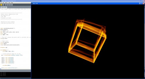
The software written in Processing By IAN allows you to immediately verify the correct operation of Freescale chip. A cube will rotate like the movements of the sensor.
The applications of this sensor are different and I will show you just developed.

//This example reads in a single byte value from 0 to 255 and graphs it.

/////////////////////////////////////////
//Basic serial communication code
//by Chang Soo Lee
//ITP, NYU
//Created 11/27/2005
/////////////////////////////////////////

//Modified by Boris Landoni
//www.open-electronics.org

import processing.serial.*;
Serial myPort;
int serial = 1;
byte s8=1, x8=0, y8=0, z8=0, cnt=0;
PFont font;
int numH = 370;  

// This will contain the pixels used to calculate the fire effect
int[][] fire;

// Flame colors
color[] palette;
float angle;
int[] calc1,calc2,calc3,calc4,calc5;

PGraphics pg;

void setup () {
    size(1500, 1000, P2D);

  // Create buffered image for 3d cube
  pg = createGraphics(width, height, P3D);

  calc1 = new int[width];
  calc3 = new int[width];
  calc4 = new int[width];
  calc2 = new int[height];
  calc5 = new int[height];

    colorMode(HSB);

  fire = new int[width][height];
  palette = new color[255];

  // Generate the palette
  for(int x = 0; x < palette.length; x++) {
    //Hue goes from 0 to 85: red to yellow
    //Saturation is always the maximum: 255
    //Lightness is 0..255 for x=0..128, and 255 for x=128..255
    palette[x] = color(x/3, 255, constrain(x*3, 0, 255));

  }

  // Precalculate which pixel values to add during animation loop
  // this speeds up the effect by 10fps
  for (int x = 0; x < width; x++) {
    calc1[x] = x % width;
    calc3[x] = (x - 1 + width) % width;
    calc4[x] = (x + 1) % width;
  }

  for(int y = 0; y < height; y++) {
    calc2[y] = (y + 1) % height;
    calc5[y] = (y + 2) % height;
  }

  //size(270, 440);
  println(Serial.list());
  myPort = new Serial(this, Serial.list()[15], 9600);
  // Load the font. Fonts must be placed within the data
  // directory of your sketch. Use Tools > Create Font
  // to create a distributable bitmap font.
  // For vector fonts, use the createFont() function.
  hint(ENABLE_NATIVE_FONTS);
  //font = loadFont("ArialMT-48.vlw");
  smooth();
    myPort.write(0x01);

}

void draw () {
  if (myPort.available() > 0) {
    serial = (myPort.read());
    s8=0;
    s8+=serial;
    switch(cnt) {
      case 0:
        x8=s8;
         break;
      case 1:
        y8=s8;
         break;
      case 2:
        z8=s8;
         break;
      default:
        cnt=0;
        break;
    }
    if(cnt<2){
      cnt++;
      return;
    }
    cnt=0;
    serialEvent();
  }
  //serial=50;
        //rect(120,numH-serial, 20, serial);
  angle = angle + 0.05;

  // Rotating wireframe cube
  pg.beginDraw();
  pg.translate(width >> 1, height >> 1);
  pg.rotateZ(radians((-x8)));
  pg.rotateX(radians(y8));
  pg.background(0);
  pg.stroke(128);
  pg.scale(80);
  pg.noFill();
  pg.box(4);
  pg.endDraw();

  loadPixels();

  int counter = 0;
    // Do the fire calculations for every pixel, from top to bottom
  for (int y = 0; y < height; y++) {
    for(int x = 0; x < width; x++) {
      // Add pixel values around current pixel

      fire[x][y] =
          ((fire[calc3[x]][calc2[y]]
          + fire[calc1[x]][calc2[y]]
          + fire[calc4[x]][calc2[y]]
          + fire[calc1[x]][calc5[y]]) << 5) / 129; 

      // Output everything to screen using our palette colors
      pixels[counter] = palette[fire[x][y]];

      // Extract the red value using right shift and bit mask
      // equivalent of red(pg.pixels[x+y*w])
      if ((pg.pixels[counter++] >> 16 & 0xFF) == 128) {
        // Only map 3D cube 'lit' pixels onto fire array needed for next frame
        fire[x][y] = 128;
      }
    }
  }
  //updatePixels();

}

void serialEvent(){

   background(255);
  line(70,70,70,370);
  line(70,270,200,270);
  line(70,370,200,370);
  fill(0);
  //textFont(font, 11);
  text("Sensor\nValue",22,80);
  text("Analog Input", 95, 390);

  noFill();

  println(x8+" "+y8+" "+z8);

  rect(100,270, 20, x8);
  rect(140,270, 20, y8);
  rect(180,270, 20, z8);
    text(s8,25,110);
        myPort.write(0x01);

}

Magnetometer and accelerometer read simultaneously

In Learning to Use I2C and Magnetometer not fried, I talked about interfacing the MAG3110 magnetometer and MQA8452Q accelerometer to an Arduino.  For both, I’m using breakout boards from Sparkfun Electronics.

I  checked today that there are no problems when I connect both devices to the same I2C bus.

The first test was very simple: I put both the breakout boards into a breadboard and wired them together, then tried running each of the programs I’d written for the chips separately. Result: no problems—worked first time.

I then tried merging the programs (cleaning up any naming conflicts) so that both could be run from the same code.  After a few typo fixes, this also worked fine

I think I’m now ready to hand over the software to the students to use for their robot.

I still need to put the i2c.h, i2c.cpp, and accel_magnet code in some public place for others to use (perhaps on github? maybe on my web pages at work?) [UPDATE 2012-jan-31: I have put the libraries and the sample code for the accelerometer and magnetometer at http://users.soe.ucsc.edu/~karplus/Arduino/]

One thing that is still missing is doing tilt correction for the compass heading.  Since the ROV is not expected to remain level (the accelerometer is intended to be used in a feedback loop to adjust the pitch, with anything from -90° to +90° being reasonable), getting a good compass heading requires rotating the magnetometer readings into the horizontal plane.  Only one of the students in the robotics club has had trigonometry or matrix math, so I’ll have to work with him to get him to figure out how to do the tilt correction. It may be simplest conceptually  to compute pitch and roll angles first, then rotate twice, rather than trying to do the whole tilt correction in one step (especially since the Arduino does not have matrix libraries).

Related articles

Tagged: accelerometer, Arduino, I²C, magnetometer, robotics, SparkFun, SparkFun Electronics

Magnetometer was not fried

MAG3110 breakout board by Sparkfun

In Learning to Use I2C, I talked about the difficulty I’d been having getting the MAG3110 breakout board from Sparkfun to work, and my fears that I had burned it out by running it overnight at 5v (instead of the rated 3v).  I suspected that my problem was really a software problem, but debugging the software when I was afraid that the hardware was fried seemed like an exercise in futility.

I bought another of the breakout boards from Sparkfun (they’re only $15), and soldered on a header yesterday.  The code failed in almost exactly the same way with the new (presumed good) part as with the old (presumed fried) part, so I was convinced that the problem was indeed in the software.

I spent half of yesterday and most of this morning carefully rewriting the library of I2C interface code.  I was starting with example code from Sparkfun for the MMA8452Q accelerometer, which I had generalized to handle other I2C devices.

The library worked fine with the accelerometer, so I thought it was ok, but it did not work with the magnetometer. I added a lot of error checking (making sure that the microprocessor was in the expected state after each I2C operation), and found that things were not working as expected. The extra error checking made it much easier to diagnose the problems. I had to re-read the I2C documentation in the ATMega328 datasheet several times, to make sure that I had all the details right (I didn’t, of course). The documentation in that data sheet is better than several of the tutorials I’ve seen on line, and is both thorough and comprehensible in describing the interface.

I did not implement all features of the I2C  interface—in fact, I have a rather minimal implementation that uses polling rather than interrupts and assumes that the Arduino will always be the bus master.  Those assumptions are fine for most Arduino projects, which just use the I2C bus for talking to a handful of peripherals, but sometime in the future I may need to make a more complete set of code that can handle multiple masters, the Arduino as a slave device, and interrupts rather than polling and waiting for operations to finish.

Because I was more interested in simplicity and robustness than speed, I rewrote the code so that transactions were finished (and appropriate status checked) before functions returned.  With these changes I found that the STOP condition was not happening, despite being requested.  All other operations on the bus are checked with the TWINT bit  of the TWCR register and the upper bits of the TWSR register, but determining that STOP has completed requires checking the TSWTO bit of the TWCR register. The code I had started from just checked the TWINT bit for the other operations, and had a fixed timeout that was too short—it did no checking at all on the STOP state, just adding a fixed delay.

Once I got the STOP timing cleaned up (and earlier, making sure to send NAK when reading the last byte), everything worked fine.  The accelerometer code  had probably worked ok because there were enough delays after stops that the stops completed, even though I had not checked to make sure.  With the fixed code, even the magnetometer that I thought I had fried seems to work ok.

The interface for the students in the Robotics Club is fairly simple (much simpler than the standard “Wire” library):

// Read one register
uint8_t i2cReadRegister(uint8_t i2c_7bit_address, uint8_t address);
// Read num_to_read registers starting at address
void i2cReadRegisters(uint8_t i2c_7bit_address, uint8_t address, uint8_t num_to_read, uint8_t * dest);

// Write one register
void i2cWriteRegister(uint8_t i2c_7bit_address, uint8_t address, uint8_t data);
// Write num_to_write registers, starting at address
void i2cWriteRegisters(uint8_t i2c_7bit_address, uint8_t address, uint8_t num_to_write, const uint8_t *data);

I suppose I should check that there are no problems when I connect both devices to the same I2C bus, before handing this over to the students to use for their robot.

I should also put the i2c.h and i2c.cpp in some public place for others to use (perhaps on github? maybe on my web pages at work?). It is really a shame that WordPress.com does not permit code-like files as pages.

Related articles

Tagged: accelerometer, Arduino, i2c, magnetometer, robotics, SparkFun, SparkFun Electronics

Learning to use I2C

For the Santa Cruz Robotics Club, I’ve bought three sensors for their underwater ROV: a magnetometer, an accelerometer, and a pressure sensor.

Originally, we were going to an ADXL335 accelerometer (with a breakout board by Adafruit Industries) and an MPXHZ6250A pressure sensor (no magnetometer), for which I designed a small PC board, but once the specs for this year’s mission came out, we saw that they wanted us to determine compass headings for a “sunken ship”, so it seemed a natural thing to add a magnetometer to the hardware.  After looking at what was available, I chose the MAG3110 breakout board from Sparkfun, because it provided a triple-axis magnetometer for only $15.

The MAG3110 is an I2C interface, which means we need only 2 wires to hook it up (and the wires can be shared with other I2C devices).  If we are going to all the trouble of figuring out an I2C interface, I figured we might as well use it for the accelerometer as well, so I got a MMA8452Q breakout board from Sparkfun also.

I decided to do a simple test program for the I2C parts before handing them over to the robotics club, so that they could be sure they had working parts.  It was a good thing I did, because I spent more than an entire day trying to get the parts to work.  I finally gave up on the “Wire” library from the Arduino website, and tried using the i2c.h file from Sparkfun (example code linked to from the accelerometer web page).  I got that working and rewrote the library as a proper .h and .cpp file, so that it could be installed as a normal Arduino library, adding some of the utility calls that had been buried in the MMA8452 demo code.

The MMA8452Q code was working fine, so I tried using the same i2c library for the MAG3110 magnetometer.

I had gotten MAG3110 working with the Wire library, but running at 5v (I’d not noticed that it was a 3.3v part—rather, I thought I’d checked that it was a 5v part, but I was wrong).  I’d left it powered at 5v all night, and I think I burned it out, as it was quite warm in the morning.  Today, I can read and write the registers of the MAG3110, but the xyz values are not coming out reasonable at all—I frequently get the same values (like 0xF9F9)and 0x1DF9), independent of the orientation. If I read all the registers, a lot of them come out as 0xF9 or 0x1D.  Even the WHO_AM_I register (which should be 0xC4) often comes out 0x1D.  I seem to get intermittent correct values for registers, but mostly bogus values.

I’ll feel stupid if I order another part and it turns out to be a software bug, but I’m pretty sure the chip is fried.  But I guess it is time to do another Sparkfun order. (I owe them some business, after calling them for the replacement photointerrupter.)

Incidentally, I tried finding a usable pressure sensor with an I2C interface, but it doesn’t look like anyone is making them except for barometric pressure ranges for dry gases.  I suppose Freescale will eventually come out with a full range of I2C pressure sensors, but my guess is that will be a long time coming, as the automotive and industrial applications have a pretty long product design cycle (unlike consumer electronics, which is driving the barometric pressure sensors).


Tagged: accelerometer, Adafruit Industries, Arduino, magnetometer, robotics, SparkFun, SparkFun Electronics