Posts with «review» label

Tutorial – 74HC4067 16-Channel Analog Multiplexer Demultiplexer

Introduction

Now and again there’s a need to expand the I/O capabilities of your chosen micorocontroller, and instead of upgrading you can often use external parts to help solve the problem. One example of this is the 74HC4067 16-channel analog multiplexer demultiplexer. That’s a mouthful – however in simple form it’s an IC that can direct a flow of current in either direction from one pin  to any one of sixteen pins. Another way to think abou it is that you can consider the 74HC4067 to be a digital replacement to those rotary switches that allow you to select one of sixteen positions.

Here’s an example of the SMD version:

Don’t let that put you off, it’s just what we had in stock at the time. The part itself is available in through-hole and surface mount versions.

Using the 74HC4067

At this point you should download the data sheet, as we refer to it through the course of the article. The first thing to note is that the 74HC4067 can operate on voltages between 2 and 6V DC, which allows use with 3.3V and 5V microcontrollers and boards such as Arduino and Raspberry Pi. If for some reason you have the 74HCT4067 it can only work on 4.5~5.5V DC.  Next – consider the pinout diagram from the data sheet:

The power supply for the part is applied to pin 24, and GND to … pin 12. Pin 15 is used to turn the control the current flow through the inputs/outputs – if this is connected to Vcc the IC stops flow, and when connected to GND it allows flow. You can always control this with a digital output pin if required, or just tie it to GND if this doesn’t matter.

Next – pin one. This is where the current either flows in to be sent to one of the sixteen outputs – or where the current flows out from one of the sixteen inputs. The sixteen inputs/outputs are labelled I0~I15. Finally there are the four control pins – labelled S0~S3. By setting these HIGH or LOW (Vcc or GND) you can control which I/O pins the current flow is directed through. So how does that work? Once again – reach for the the data sheet and review the following table:

Not only does it show what happens when pin 15 is set to HIGH (i.e. nothing) it shows what combination of HIGH and LOW for the control pins are required to select which I/O pin the current will flow through. If you scroll down a bit hopefully you noticed that the combination of S0~S3 is in fact the binary equivalent of the pin number – with the least significant bit first. For example, to select pin 9 (9 in binary is 1001) you set the IC pins S0 and S3 to HIGH, and S1 and S2 to LOW. How you control those control pins is of course up to you – either with some digital logic circuit for your application or as mentioned earlier with a microcontroller.

Limitations 

Apart from the power supply requirements, there are a few limitations to keep in mind. Open you data sheet and consider the “DC Electrical Specifications” table. The first two parameters show what the minimum voltage that can be considered as a HIGH and the maximum for a LOW depending on your supply voltage. The next item of interest is the “ON” resistance – that is the resistance in Ohms (Ω) between one of the sixteen inputs/outputs and the common pin. When a channel is active, and a 5V supply voltage, we measured a resistance of 56Ω without a load through that channel – and the data sheet shows other values depending on the current load and supply voltage. Finally, don’t try and run more than 25 mA of current through a pin.

Examples

Now to show an example of both multiplexing and demultiplexing. For demonstration purposes we’re using an Arduino Uno-compatible board with the 74HC4067 running from a 5V supply voltage. Pin 15 of the ‘4067 is set to GND, and control pins S0~S3 are connected to Arduino digital output pins D7~D4 respectively.

Multiplexing

This is where we select one input pin of sixteen and allow current to flow through to the common pin (1). In this example we connect the common pin to the board’s analog input pin – so this can be used as a method of reading sixteen analog signals (one at a time) using only one ADC. When doing so – take note of the limitations mentioned earlier – take some resistance measurements in your situation to determine what the maximum value will be from your ADC and calibrate code accordingly.

With both of the examples we’ll use port manipulation to control the digital pins which are connected to the 74HC4067’s control pins. We do this as it reduces the code required and conceptually I feel it’s easier. For example – to select I/O 15 you need to turn on all the control pins – so you just have to set Arduino PORTD to B11110000 (which is binary 15 LSB first) and much neater than using four digitalWrite() functions.

In the following example sketch, you can see how we’ve put the binary values for each control possibility in the array byte controlPins[] – which is then used to set the pins easily in void loop().

This simply sets each input pin in turn, then reads the ADC value into an array – whose values are then sent to the serial monitor:

// 74HC4067 multiplexer demonstration (16 to 1)

// control pins output table in array form
// see truth table on page 2 of TI 74HC4067 data sheet
// connect 74HC4067 S0~S3 to Arduino D7~D4 respectively
// connect 74HC4067 pin 1 to Arduino A0
byte controlPins[] = {B00000000, 
                  B10000000,
                  B01000000,
                  B11000000,
                  B00100000,
                  B10100000,
                  B01100000,
                  B11100000,
                  B00010000,
                  B10010000,
                  B01010000,
                  B11010000,
                  B00110000,
                  B10110000,
                  B01110000,
                  B11110000 }; 

// holds incoming values from 74HC4067                  
byte muxValues[] = {0,0,0,0,0,0,0,0,0,0,0,0,0,0,0,0,};

void setup()
{
  Serial.begin(9600);
  DDRD = B11111111; // set PORTD (digital 7~0) to outputs
}

void setPin(int outputPin)
// function to select pin on 74HC4067
{
  PORTD = controlPins[outputPin];
}

void displayData()
// dumps captured data from array to serial monitor
{
  Serial.println();
  Serial.println("Values from multiplexer:");
  Serial.println("========================");
  for (int i = 0; i < 16; i++)
  {
    Serial.print("input I"); 
    Serial.print(i); 
    Serial.print(" = "); 
    Serial.println(muxValues[i]);
  }
  Serial.println("========================");  
}

void loop()
{
  for (int i = 0; i < 16; i++)
  {
    setPin(i); // choose an input pin on the 74HC4067
    muxValues[i]=analogRead(0); // read the vlaue on that pin and store in array
  }

  // display captured data
  displayData();
  delay(2000); 
}

… and a quick video of the results:

Demultiplexing

Now for the opposite function – sending current from the common pin to one of sixteen outputs. A fast example of this is by controlling one of sixteen LEDs each connected to an output pin, and with 5V on the 74HC4067 common pin. We don’t need current-limiting resistors for the LEDs due to the internal resistance in the 74HC4067. Here’s the sketch:

// 74HC4067 demultiplexer demonstration (1 to 16)

// control pins output table in array form
// see truth table on page 2 of TI 74HC4067 data sheet
// connect 74HC4067 S0~S3 to Arduino D7~D4 respectively
// 5V to 74HC4067 pin 1 to power the LEDs :)
byte controlPins[] = {B00000000, 
                      B10000000,
                      B01000000,
                      B11000000,
                      B00100000,
                      B10100000,
                      B01100000,
                      B11100000,
                      B00010000,
                      B10010000,
                      B01010000,
                      B11010000,
                      B00110000,
                      B10110000,
                      B01110000,
                      B11110000 }; 

void setup()
{
  DDRD = B11111111; // set PORTD (digital 7~0) to outputs
}

void setPin(int outputPin)
// function to select pin on 74HC4067
{
  PORTD = controlPins[outputPin];
}

void loop()
{
  for (int i = 0; i < 16; i++)
  {
    setPin(i);
    delay(250);
  }
}

… and the LEDs in action:

Conclusion

If you’re considering the 74HC4067 or hadn’t known about it previously, we hope you found this of interest. If you have any questions please leave them below or privately via the contact page. And if you made it this far – check out my new book “Arduino Workshop” from No Starch Press.

In the meanwhile have fun and keep checking into tronixstuff.com. Why not follow things on twitterGoogle+, subscribe  for email updates or RSS using the links on the right-hand column? And join our friendly Google Group – dedicated to the projects and related items on this website. Sign up – it’s free, helpful to each other –  and we can all learn something.


The post Tutorial – 74HC4067 16-Channel Analog Multiplexer Demultiplexer appeared first on tronixstuff.

Australian Electronics Nostalgia – Talking Electronics Kits

Introduction

From 1981, Australian electrical engineer Colin Mitchell started publishing his home-grown electronics magazine “Talking Electronics”. His goal was to get people interested and learning about electronics, and more so with a focus on digital electronics. It was (and still is) a lofty goal – in which he succeeded. From a couple of rooms in his home the magazine flourished, and many projects described within were sold as kits. At one stage there were over 150 Talking Electronics kits on the market. You could find the books and kits in retail outlets such as Dick Smith Electronics, and for a short while there was a TE store in Moorabbin (Victoria). Colin and the team’s style of writing was easy to read and very understandable – but don’t take my word for it, you can download the magazines from his website (they’re near the bottom of the left column). Dave Jones recently interviewed Colin, and you can watch those for much more background information.

Over fifteen issues you could learn about blinking LEDs all the way to making your own expandable Z80 board computer, and some of the kits may still be available. Colin also published a series of tutorial books on electronics, and also single-magazine projects. And thus the subjects of our review … we came across the first of these single-issue projects from 1981 – the Mini Frequency Counter (then afterwards we have another kit):

How great is that? The PCB comes with the magazine. This is what set TE apart from the rest, and helped people learn by actually making it easy to build what was described in the magazine instead of just reading about it. For 1981 the PCB was quite good – they were silk-screened which was quite rare at the time:

And if you weren’t quite ready, the magazine also included details of a square-wave oscillator to make and a 52-page short course in digital electronics. However back to the kit…

Assembly

The kit uses common parts and I hoard CMOS ICs so building wasn’t a problem. This (original) version of the kit used LEDs instead of 7-segment displays (which were expensive at the time) so there was plenty of  careful soldering to do:

And after a while the counter started to come together. I used IC sockets just in case:

The rest was straight-forward, and before long 9 V was supplied, and we found success:

To be honest progress floundered for about an hour at this point – the display wouldn’t budge off zero. After checking the multi-vibrator output, calibrating the RC circuits and finally tracing out the circuit with a continuity tester, it turned out one of the links just wasn’t soldered in far enough – and the IC socket for the 4047 was broken So a new link and directly fitting the 4047 fixed it. You live and learn.

Operation

So – we now have a frequency counter that’s good for 100 Hz to the megahertz range, with a minimum of parts. Younger, non-microcontroller people may wonder how that is possible – so here’s the schematic:

The counter works by using a multi-vibrator using a CD4047 to generate a square-wave at 50, 500 and 5 kHz, and the three trimpots are adjusted to calibrate the output. The incoming pulses to measure are fed to the 4026 decade counter/divider ICs. Three of these operate in tandem and each divide the incoming count by ten – and display or reset by the alternating signal from the 4047. However for larger frequencies (above 900 Hz) you need to change the frequency fed to the display circuit in order to display the higher (left-most) digits of the result. A jumper wire is used to select the required level (however if you mounted the kit in a case, a knob or switch could be used).

For example, if you’re measuring 3.456 MHz you start with the jumper on H and the display reads 345 – then you switch to M to read 456 – then you switch to the L jumper and read 560, giving you 3456000 Hz. If desired, you can extend the kit with another PCB to create a 5-digit display. The counter won’t be winning any precision contests – however it has two purposes, which are fulfilled very well. It gives the reader an inexpensive piece of test equipment that works reasonably well, and a fully-documented project so the reader can understand how it works (and more).

And for the curious –  here it is in action:

[Update 20/07/2013] Siren Kit

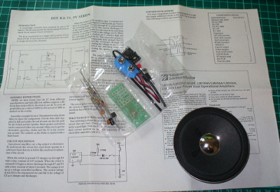
Found another kit last week, the Talking Electronics “DIY Kit #31 – 9V siren”. It’s an effective and loud siren with true rise and fall, unlike other kits of the era that alternated between two fixed tones. The packaging was quite strong and idea for mail-order at the time:

The label sells the product (and shows the age):

The kit included every part required to work, apart from a PP3 battery, and a single instruction sheet with a good explanation of how the circuit works, and some data about the LM358:

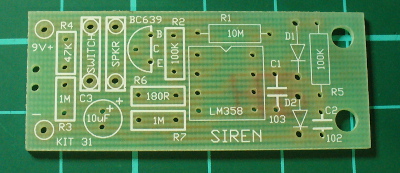
… and as usual the PCB was ahead of its’ time with full silk-screen and solder mask:

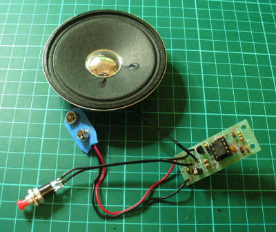
Assembly was quite straight-forward. The design is quite compact, so a lot of vertical resistor mounting was necessary due to the lack of space. However it was refreshing to not have any links to fit. After around twenty minutes of relaxed construction, it was ready to test:

It’s a 1/2 watt speaker, however much louder than originally anticipated:

Once again, another complete and well-produced kit.

Conclusion

That was a lot of fun, and I’m off to make the matching square-wave oscillator for the frequency counter. Kudos to Colin for all those years of publication and helping people learn. Lots of companies bang on about offering tutorials and information on the Internet for free, but Colin has been doing it for over ten years. Check out his Talking Electronics website for a huge variety of knowledge, an excellent electronics course you can get on CD – and go easy on him if you have any questions.

Full-sized images available on flickr. This kit was purchased without notifying the supplier.

And if you made it this far – check out my new book “Arduino Workshop” from No Starch Press.

In the meanwhile have fun and keep checking into tronixstuff.com. Why not follow things on twitterGoogle+, subscribe  for email updates or RSS using the links on the right-hand column? And join our friendly Google Group – dedicated to the projects and related items on this website. Sign up – it’s free, helpful to each other –  and we can all learn something.

The post Australian Electronics Nostalgia – Talking Electronics Kits appeared first on tronixstuff.

Arduino-compatible VFD modular clock from Akafugu

There aren't many VFD clock kits out there that are software-compatible with Arduino (and by that I mean the "Arduino sketch" being compilable in Arduino IDE and uploadable through USB-FTDI).
Most of these kits come with the microcontroller pre-programmed, so they can be built quickly and easily, with minimal effort (totally understandable instant gratification; nobody wants to end up with an expensive dud). Upgrading the software usually requires familiarity with the microcontroller toolchain (compile-build-flash), plus an ISP programmer. (Note: The only processor I am familiar with is AVR/Atmega.)

I was going to build myself an Arduino-based VFD clock, one that can take a sketch through the FTDI cable. Instead of starting from scratch (choosing a schematic, making the board etc), I decided to try one of the only 2 open-source VFD clock kits I found that are based on Atmega processor and :

I settled for the VFD modular clock because the Akafugu people offered me the pair of PCBs in their kit (for a very reasonable $19, shipping included) and also because I already had most of the parts, including the two SMDs (that come pre-soldered in the kit: ATmega328 and HV5812) and the IV-17 VFD tubes.


I built the clock following their great assembling instructions, but, as you will see, not without hitting a few stumbling blocks on the way.

I should clarify that this post is not a review of the VFD modular clock kit (since I did not have the kit), but just a record of my observations. It was my choice to not use the kit, thus forcing myself to try to understand the schematic and the software.

Since my goal was to make the VFD modular clock Arduino-compatible, I was aware of the challenges awaiting me:
- burning the bootloader for ATmega328 with internal 8MHz oscillator;
- connecting a makeshift FTDI header;
- adapting the software to work in Arduino IDE;

Once I figured out the fuses, burning the bootloader was straightforward. For this purpose I created this section in boards.txt:

intclock328.name= ATmega328 Internal clock 8MHz
intclock328.upload.protocol=stk500
intclock328.upload.maximum_size=30720
intclock328.upload.speed=57600
intclock328.bootloader.low_fuses=0xE2
intclock328.bootloader.high_fuses=0xDA
intclock328.bootloader.extended_fuses=0x05
intclock328.bootloader.path=atmega
intclock328.bootloader.file=ATmegaBOOT_168_atmega328_pro_8MHz.hex
intclock328.bootloader.unlock_bits=0x3F
intclock328.bootloader.lock_bits=0x0F
intclock328.build.mcu=atmega328p
intclock328.build.f_cpu=8000000L
intclock328.build.core=arduino

Then I checked that the bootloader works, by uploading a simple sketch that outputs on D9 (which is connected to the buzzer). Before doing this, I had to connect the FTDI breakout to the board. Luckily (more probably intentionally), all of the required pins (Rx, Tx, Vcc, Gnd, Rst) are broken out on the female header, so just using wires worked, as shown in the next photo. This is not a nice solution though, since the top board (with the VFDs) needs to be removed before every sketch upload. (Hopefully the Akafugu team will also include an FTDI header in the next revision.)


After I soldered all the parts on the base board, I realized the biggest problem of them all: some parts (sourced by me, and obviously of different size than those in the kit) stuck well above the two lateral headers, so the display shield (upper board) could not be plugged in the base board. Almost a showstopper at this point. The solution was to replace the tall 330uF/16V capacitor, bend both 47uF capacitors sideways, replace the 330uF/50V with a pair of thinner 100uF, push both inductors as much into the PCB as possible, then cut the top plastic wrapping on one of them. These, combined with the male headers not being flush to the display board when I soldered them, did the trick. I managed to have the clock looking as intended by its creators (if you don't look too closely), as shown in the next photo.


The Akafugu designers tried to minimize the size of the clock, leaving little room for flexibility (that is, ability to use a broader range of components, of different sizes eventually). The sizes for the chosen components (especially the capacitors and the inductors) are really unique, any deviation would lead to the boards not fitting together.
Using (smaller) SMD components would not be a good solution, since these would also need to be pre-soldered (or otherwise potential non-SMD-soldering clients would be excluded). The only compromise I can think of is enlarging the base board a little bit, keeping in mind that this 4-tube version is the smallest of the display boards, all others extending laterally beyond both sides of the base board.

And finally, the last challenge: the software. I started from the original C code published here. This was written for the avr-gcc compiler and produces a hex file, which is then flashed onto the processor (no bootloader needed, nor provided) using an ISP programmer.

I changed the code (available here), mostly cosmetically, to compile with Arduino 1.0. It does not require any other external libraries and it includes its own I2C/Wire functions (does not use Arduino's Wire library).

In the end, I have an Arduino-compatible Akafugu VFD modular clock that looks just like the original one (I need to add the spacers though).


Wise time with Arduino 21 Jun 04:39
general  hacking  nixie  review  

Book – “Arduino Workshop – A Hands-On Introduction with 65 Projects”

Over the last few years I’ve been writing a few Arduino tutorials, and during this time many people have mentioned that I should write a book. And now thanks to the team from No Starch Press this recommendation has morphed into my new book – “Arduino Workshop“:

Although there are seemingly endless Arduino tutorials and articles on the Internet, Arduino Workshop offers a nicely edited and curated path for the beginner to learn from and have fun. It’s a hands-on introduction to Arduino with 65 projects – from simple LED use right through to RFID, Internet connection, working with cellular communications, and much more.

Each project is explained in detail, explaining how the hardware an Arduino code works together. The reader doesn’t need any expensive tools or workspaces, and all the parts used are available from almost any electronics retailer. Furthermore all of the projects can be finished without soldering, so it’s safe for readers of all ages.

The editing team and myself have worked hard to make the book perfect for those without any electronics or Arduino experience at all, and it makes a great gift for someone to get them started. After working through the 65 projects the reader will have gained enough knowledge and confidence to create many things – and to continue researching on their own. Or if you’ve been enjoying the results of my thousands of hours of work here at tronixstuff, you can show your appreciation by ordering a copy for yourself or as a gift

You can review the table of contents, index and download a sample chapter from the Arduino Workshop website.

Arduino Workshop is available from No Starch Press in printed or ebook (PDF, Mobi, and ePub) formats. Ebooks are also included with the printed orders so you can get started immediately.

In the meanwhile have fun and keep checking into tronixstuff.com. Why not follow things on twitterGoogle+, subscribe  for email updates or RSS using the links on the right-hand column? And join our friendly Google Group – dedicated to the projects and related items on this website. Sign up – it’s free, helpful to each other –  and we can all learn something.

The post Book – “Arduino Workshop – A Hands-On Introduction with 65 Projects” appeared first on tronixstuff.

Tutorial – Arduino and ILI9325 colour TFT LCD modules

Learn how to use inexpensive ILI9325 colour TFT LCD modules in chapter fifty of a series originally titled “Getting Started/Moving Forward with Arduino!” by John Boxall – A tutorial on the Arduino universe. The first chapter is here, the complete series is detailed here.

Introduction

Colour TFT LCD modules just keep getting cheaper, so in this tutorial we’ll show you how to get going with some of the most inexpensive modules we could find. The subject of our tutorial is a 2.8″ 240 x 320 TFT module with the ILI9325 LCD controller chip. If you look in ebay this example should appear pretty easily, here’s a photo of the front and back to help identify it:

There is also the line “HY-TFT240_262k HEYAODZ110510” printed on the back of the module. They should cost less than US$10 plus shipping. Build quality may not be job number one at the factory so order a few, however considering the cost of something similar from other retailers it’s cheap insurance. You’ll also want sixteen male to female jumper wires to connect the module to your Arduino.

Getting started

To make life easier we’ll use an Arduino library “UTFT” written for this and other LCD modules. It has been created by Henning Karlsen and can be downloaded from his website. If you can, send him a donation – this library is well worth it. Once you’ve downloaded and installed the UTFT library, the next step is to wire up the LCD for a test.

Run a jumper from the following LCD module pins to your Arduino Uno (or compatible):

  • DB0 to DB7 > Arduino D0 to D7 respectively
  • RD > 3.3 V
  • RSET > A2
  • CS > A3
  • RW > A4
  • RS > A5
  • backlight 5V > 5V
  • backlight GND > GND

Then upload the following sketch – Example 50.1. You should be presented with the following on your display:

If you’re curious, the LCD module and my Eleven board draws 225 mA of current. If that didn’t work for you, double-check the wiring against the list provided earlier. Now we’ll move forward and learn how to display text and graphics.

Sketch preparation

You will always need the following before void setup():

#include "UTFT.h"
UTFT myGLCD(ILI9325C,19,18,17,16); // for Arduino Uno

and in void setup():

myGLCD.InitLCD(orientation); 
myGLCD.clrScr();

with the former command, change orientation to either LANDSCAPE to PORTRAIT depending on how you’ll view the screen. You may need further commands however these are specific to features that will be described below. The function .clrScr() will clear the screen.

Displaying Text

There are three different fonts available with the library. To use them add the following three lines before void setup():

extern uint8_t SmallFont[];
extern uint8_t BigFont[];
extern uint8_t SevenSegNumFont[];

When displaying text you’ll need to define the foreground and background colours with the following:

myGLCD.setColor(red, green, blue); 
myGLCD.setBackColor(red, green, blue);

Where red, green and blue are values between zero and 255. So if you want white use 255,255,255 etc. For some named colours and their RGB values, click here. To select the required font, use one of the following:

myGLCD.setFont(SmallFont); // Allows 20 rows of 40 characters
myGLCD.setFont(BigFont); // Allows 15 rows of 20 characters
myGLCD.setFont(SevenSegNumFont); // allows display of 0 to 9 over four rows

Now to display the text use the function:

myGLCD.print("text to display",x, y);

where text is what you’d like to display, x is the horizontal alignment (LEFT, CENTER, RIGHT) or position in pixels from the left-hand side of the screen and y is the starting point of the top-left of the text. For example, to start at the top-left of the display y would be zero. You can also display a string variable instead of text in inverted commas.

You can see all this in action with the following sketch – Example 50.2, which is demonstrated in the following video:

Furthremore, you can also specify the angle of display, which gives a simple way of displaying text on different slopes. Simply add the angle as an extra parameter at the end:

myGLCD.print("Hello, world", 20, 20, angle);

Again, see the following sketch – Example 50.2a, and the results below:

Displaying Numbers

Although you can display numbers with the text functions explained previously, there are two functions specifically for displaying integers and floats.

You can see these functions in action with the following sketch – Example 50.3, with an example of the results below:

Displaying Graphics

There’s a few graphic functions that can be used to create required images. The first is:.

myGLCD.fillScr(red, green, blue);

which is used the fill the screen with a certain colour. The next simply draws a pixel at a specified x,y location:

myGLCD.drawPixel(x,y);

Remember that the top-left of the screen is 0,0. Moving on, to draw a single line, use:

myGLCD.drawLine(x1,0,x2,239);

where the line starts at x1,y1 and finishes at x2,y2. Need a rectangle? Use:

myGLCD.drawRect(x1,y2,x2,y2); // for open rectangles
myGLCD.fillRect(x1,y2,x2,y2); // for filled rectangles

where the top-left of the rectangle is x1,y1 and the bottom-right is x2, y2. You can also have rectangles with rounded corners, just use:

myGLCD.drawRoundRect(x1,y2,x2,y2); // for open rectangles
myGLCD.fillRoundRect(x1,y2,x2,y2); // for filled rectangles

instead. And finally, circles – which are quite easy. Just use:

myGLCD.drawCircle(x,y,r); // draws open circle
myGLCD.fillCircle(x,y,r); // draws a filled circle

where x,y are the coordinates for the centre of the circle, and r is the radius. For a quick demonstration of all the graphic functions mentioned so far, see Example 50.4 – and the following video:

Displaying bitmap images

If you already have an image in .gif, .jpg or .png format that’s less than 300 KB in size, this can be displayed on the LCD. To do so, the file needs to be converted to an array which is inserted into your sketch. Let’s work with a simple example to explain the process. Below is our example image:

Save the image of the puppy somewhere convenient, then visit this page. Select the downloaded file, and select the .c and Arduino radio buttons, then click “make file”. After a moment or two a new file will start downloading. When it arrives, open it with a text editor – you’ll see it contains a huge array and another #include statement – for example:

Past the #include statement and the array into your sketch above void setup(). After doing that, don’t be tempted to “autoformat” the sketch in the Arduino IDE. Now you can use the following function to display the bitmap on the LCD:

myGLCD.drawBitmap(x,y,width,height, name, scale);

Where x and y are the top-left coordinates of the image, width and height are the … width and height of the image, and name is the name of the array. Scale is optional – you can double the size of the image with this parameter. For example a value of two will double the size, three triples it – etc. The function uses simple interpolation to enlarge the image, and can be a clever way of displaying larger images without using extra memory. Finally, you can also display the bitmap on an angle – using:

myGLCD.drawBitmap(x,y,width,height, name, angle, cx, cy);

where angle is the angle of rotation and cx/cy are the coordinates for the rotational centre of the image.

The bitmap functions using the example image have been used in the following sketch – Example 50.5, with the results in the following video:

Unfortunately the camera doesn’t really do the screen justice, it looks much better with the naked eye.

What about the SD card socket and touch screen?

The SD socket didn’t work, and I won’t be working with the touch screen at this time.

Conclusion

So there you have it – an incredibly inexpensive and possibly useful LCD module. Thank you to Henning Karlsen for his useful library, and if you found it useful – send him a donation via his page.

In the meanwhile have fun and keep checking into tronixstuff.com. Why not follow things on twitterGoogle+, subscribe  for email updates or RSS using the links on the right-hand column? And join our friendly Google Group – dedicated to the projects and related items on this website. Sign up – it’s free, helpful to each other –  and we can all learn something.

The post Tutorial – Arduino and ILI9325 colour TFT LCD modules appeared first on tronixstuff.

Tronixstuff 26 Apr 02:31

Exploring the TI Stellaris platform with Energia Arduino-compatible IDE

Introduction

In the same manner as their MSP430 development board, Texas Instruments also have another LaunchPad board with their powerful Stellaris LM4F120H5QR microcontroller. It’s an incredibly powerful and well-featured MCU – which offers an 80 MHz, 32-bit ARM Cortex-M4 CPU with floating point, 256 Kbytes of 100,000 write-erase cycle FLASH and many peripherals such as 1MSPS ADCs, eight UARTs, four SPIs, four I2Cs, USB & up to 27 timers, some configurable up to 64-bits.

That’s a bucket of power, memory and I/O for not much money – you can get the LaunchPad board for around $15. This LaunchPad has the in-circuit debugger, two user buttons, an RGB LED and connectors for I/O and shield-like booster packs:

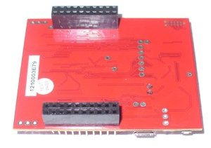
and the other side:

However the good news as far as we’re concerned is that you can now use it with the Energia Arduino-compatible IDE that we examined previously. Before rushing out to order your own Stellaris board, install Energia and examine the available functions and libraries to make sure you can run what you need. And if so, you’re set for some cheap Arduino power.

Installation

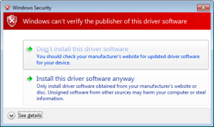
Installation is simple, just get your download from here. If you’re running Windows 7 – get the USB drivers from here. When you plug your LaunchPad into the USB for the first time, wait until after Windows attempts to install the drivers, then install drivers manually after download via Device manager … three times (JTAG, virtual serial port and DFU device). Use the debug USB socket (and set the switch to debug) when installing and uploading code. If you get the following warning from Windows, just click “Install this driver software anyway”:

Once the drivers are installed, plug in your LaunchPad, wait a moment – then run Energia. You can then select your board type and serial port just like the Arduino IDE. Then go ahead and upload the “blink” example…

Awesome – check out all that free memory space. In the same manner as the MSP430, there are some hardware<>sketch differences you need to be aware of. For example, how to refer to the I/O pins in Energia? A map has been provided for front:

… and back:

As you can imagine, the Stellaris MCUs are different to an AVR, so a lot of hardware-specific code doesn’t port over from the world of Arduino. One of the first things to remember is that the Stellaris is a 3.3V device. Code may or may not be interchangeable, so a little research will be needed to match up the I/O pins and rewrite the sketch accordingly. For example, instead of digital pins numbers, you use PX_Y – see the map above. So let’s say you want to run through the RGB LED… consider the following sketch:

int wait = 500;
void setup() 
{ 
 // initialize the digital pin as an output.
 pinMode(PF_1, OUTPUT); // red 
 pinMode(PF_3, OUTPUT); // green
 pinMode(PF_2, OUTPUT); // blue
}
void loop() 
{
 digitalWrite(PF_1, HIGH); 
 delay(wait); 
 digitalWrite(PF_1, LOW); 
 digitalWrite(PF_3, HIGH); 
 delay(wait); 
 digitalWrite(PF_3, LOW); 
 digitalWrite(PF_2, HIGH); 
 delay(wait); 
 digitalWrite(PF_2, LOW); 
}

Which simply blinks the red, green and blue LED elements in series. Using digital inputs is in the same vein, and again the buttons are wired so when pressed they go LOW. An example of this in the following sketch:

void setup() 
{ 
 // initialize the digital pins
 pinMode(PF_1, OUTPUT); // red 
 pinMode(PF_3, OUTPUT); // green
 pinMode(PF_2, OUTPUT); // blue

 pinMode(PF_4, INPUT_PULLUP); // left - note _PULLUP
 pinMode(PF_0, INPUT_PULLUP); // right - note _PULLUP 
}
void blinkfast() 
{
 for (int i=0; i<10; i++)
 {
 digitalWrite(PF_1, HIGH); 
 delay(250); 
 digitalWrite(PF_1, LOW); 
 digitalWrite(PF_3, HIGH); 
 delay(250); 
 digitalWrite(PF_3, LOW); 
 digitalWrite(PF_2, HIGH); 
 delay(250); 
 digitalWrite(PF_2, LOW); 
 }
}
void blinkslow() 
{
 for (int i=0; i<5; i++)
 {
 digitalWrite(PF_1, HIGH); 
 delay(1000); 
 digitalWrite(PF_1, LOW); 
 digitalWrite(PF_3, HIGH); 
 delay(1000); 
 digitalWrite(PF_3, LOW); 
 digitalWrite(PF_2, HIGH); 
 delay(1000); 
 digitalWrite(PF_2, LOW); 
 }
}
void loop()
{
 if (digitalRead(PF_4)==LOW) { blinkslow(); }
 if (digitalRead(PF_0)==LOW) { blinkfast(); }
}

And for the non-believers:

Where to from here? 

Sometimes you can be platform agnostic, and just pick something that does what you want with the minimum of time and budget. Or to put it another way, if you need a fast CPU and plenty of space but couldn’t be bothered don’t have time to work with Keil, Code Composer Studio, IAR etc – the Energia/Stellaris combination could solve your problem. There’s a growing Energia/Stellaris forum, and libraries can be found here. At the time of writing we found an I2C library as well.

However to take full advantage of the board, consider going back to the TI tools and move forward with them. You can go further with the tutorials and CCS etc from Texas Instruments own pages.

In the meanwhile have fun and keep checking into tronixstuff.com. Why not follow things on twitterGoogle+, subscribe  for email updates or RSS using the links on the right-hand column? And join our friendly Google Group – dedicated to the projects and related items on this website. Sign up – it’s free, helpful to each other –  and we can all learn something.

The post Exploring the TI Stellaris platform with Energia Arduino-compatible IDE appeared first on tronixstuff.

MakerLab reviews the Arduino Starter Kit

When we released the Arduino Kit, we knew that we are equiping the closet-wannabe-makers to start planning for world domination. Now it has the stamp of approval from MakerLab too!

Make Noise With The New Arduino Kit is a project by Alessandro Contini (@CNTLSN) and Alberto Massa (@nkint)

The above video explores the basic components of the kit and things that a new-maker would want to start with, including a light controlled theramin, and by theramin, I really mean exploring every possibe way to make impressive noises from one simple experiment.

Sounds fun? Do write to us, what you made out of your starter kit. We may feature you next

Via:[MakerLab]

Arduino Blog 22 Jan 11:45

Review: Gooligum Electronics PIC Training Course and Development Board

Introduction

[Updated 18/06/2013]

There are many types of microcontrollers on the market, and it would be fair to say one of the two most popular types is the Microchip PIC series. The PICs are great as there is a huge range of microcontrollers available across a broad range of prices. However learning how to get started with the PIC platform isn’t exactly simple. Not that we expect it to be, however a soft start is always better. There are some older books, however they can cost more than $100 – and are generally outdated. So where do you start?

It is with this problem in mind that led fellow Australian David Meiklejohn to develop and offer his PIC Training Course and Development Board to the marketplace via his company Gooligum Electronics.

In his words:

There is plenty of material available on PICs, which can make it daunting to get started.  And some of the available material is dated, originally developed before modern “flash” PICs were available, or based on older devices that are no longer the best choice for new designs.  Our approach is to introduce PIC programming and design in easy stages, based on a solid grounding in theory, creating a set of building blocks and techniques and giving you the confidence to draw on as we move up to more complex designs.

So in this article we’ll examine David’s course package. First of all, let’s look at the development board and inclusions. Almost everything you will need to complete all the lessons is included in the package, including the following PIC microcontrollers:

You can choose to purchase the board in kit form or pre-assembled. If you enjoy soldering, save the money and get the kit – it’s simple to assemble and a nice way to spend a few hours with a soldering iron.

Although the board includes all the electronic components and PICs – you will need are a computer capable of running Microchip MPLAB software, a Microchip PICkit3 (or -2) programming device and an IC extractor. If you’re building the kit, a typical soldering iron and so on will be required. Being the  ultra-paranoid type, I bought a couple extra of each PIC to have as spares, however none were damaged in my experimenting. Just use common-sense when handling the PICs and you will be fine.

Assembly

Putting the kit board together wasn’t difficult at all. There isn’t any surface-mount parts to worry about, and the PCB is silk-screened very well:

The rest of the parts are shipped in antistatic bags, appropriately labelled and protected:

Assembly was straight forward, just start with the low-profile parts and work your way up. The assembly guide is useful to help with component placement. After working at a normal pace, it was ready in just over an hour:

The Hardware

Once assembled (or you’ve opened the packaging) the various sections of the board are obvious and clearly labelled – as they should be for an educational board. You will notice a large amount of jumper headers – they are required to bridge in and out various LEDs, select various input methods and so on. A large amount of jumper shunts is included with the board.

It might appear a little disconcerting at first, but all is revealed and explained as you progress through the lessons. The board has decent rubber feet, and is powered either by the PICkit3 programmer, or a regulated DC power source between 5 and 6V DC, such as from a plug-pack if you want to operate your board away from a PC.

However there is a wide range of functions, input and output devices on the board – and an adjustable oscillator, as shown in the following diagram:

The Lessons

There is some assumed knowledge, which is a reasonable understanding of basic electronics, some computer and mathematical savvy and the C programming language.

You can view the first group of lessons for free on the kit website, and these are included along with the additional lessons in the included CDROM. They’re in .pdf format and easy to read. The CDROM also includes all the code so you don’t have to transcribe it from the lessons. Students start with an absolute introduction to the system, and first learn how to program in assembly language in the first group of tutorials, followed by C in the second set.

This is great as you learn about the microcontroller itself, and basically start from the bottom. Although it’s no secret I enjoy using the Arduino system – it really does hide a lot of the actual hardware knowledge away from the end user which won’t be learned. With David’s system – you will learn.

If you scroll down to the bottom of this page, you can review the tutorial summaries. Finally here’s a quick demonstration of the 7-segment displays in action:

Update – 18/06/2013

David has continued publishing more tutorials for his customers every few months – including such topics as the EEPROM and pulse-width modulation. As part of the expanded lessons you can also get a pack which allows experimenting with electric motors that includes a small DC motor, the TI SN75441 h-bridge IC, N-channel and P-channel MOSFETS and more:

So after the initial purchase, you won’t be left on your own. Kudos to David for continuing to support and develop more material for his customers.

Where to from here? 

Once you run through all the tutorials, and feel confident with your knowledge, the world of Microchip PIC will be open to you. Plus you now have a great development board for prototyping with 6 to 14-pin PIC microcontrollers. Don’t forget all the pins are brought out to the row of sockets next to the solderless breadboard, so general prototyping is a breeze.

Conclusion

For those who have mastered basic electronics, and have some C or C-like programming experience from using other development environments or PCs – this package is perfect for getting started with the Microchip PIC environment. Plus you’ll learn about assembly language – which is a good thing. I genuinely recommend this to anyone who wants to learn about PIC and/or move into more advanced microcontroller work. And as the entire package is cheaper than some books –  you can’t go wrong. The training course is available directly from the Gooligum website.

Disclaimer – The Baseline and Mid-Range PIC Training Course and Development Board was a promotional consideration from Gooligum Electronics.

In the meanwhile have fun and keep checking into tronixstuff.com. Why not follow things on twitterGoogle+, subscribe  for email updates or RSS using the links on the right-hand column? And join our friendly Google Group – dedicated to the projects and related items on this website. Sign up – it’s free, helpful to each other –  and we can all learn something.

The post Review: Gooligum Electronics PIC Training Course and Development Board appeared first on tronixstuff.

Sphero goes modular, spins out for a drive (video)


Sphero's hooked up with a new whip, albeit a retro-fitted one. Skylar, a Junior Developer at Orbotix, modded an old RC car with an Arduino board, H-bridge and a few trackball parts, enabling the remote control ball to serve as its brain. Just in time too -- there's only so much fun you can have getting the little orb stuck behind the filing cabinets. Still, it's certainly a leap beyond purposing it to pull an iPhone-toting chariot.

Sean Buckley contributed to this post.

Sphero goes modular, spins out for a drive (video) originally appeared on Engadget on Mon, 19 Mar 2012 02:36:00 EST. Please see our terms for use of feeds.

Permalink | Email this | Comments