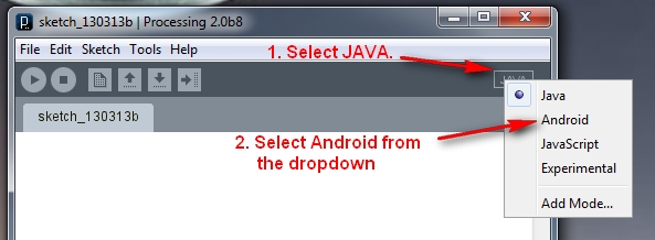
Posts with «project» label

Grove Button Tutorial

The Grove Button is a handy little component which simplifies the push-button experience. It doesn't take much programming to get this component to work. And while the button works extremely well with the Grove Base Shield, we will be connecting this button directly to the Arduino UNO.

The button will be LOW in its normal resting state, and report HIGH when the button is pressed. Have a look at the video below to see this project in action.

Video


Parts Required


Sketch


Arduino Sketch


 1
2
3
4
5
6
7
8
9
10
11
12
/* Grove Button Sketch - Written by ScottC 22nd Dec 2013 
http://arduinobasics.blogspot.com
--------------------------------------------------------- */

void setup(){
pinMode(8, INPUT);
pinMode(13, OUTPUT);
}

void loop(){
digitalWrite(13, digitalRead(8));
}

The signal pin of the Grove Button attaches to digital pin 8 on the Arduino, and the LED is connected to digital pin 13 on the Arduino. When the button is pressed, it will send a HIGH signal to digital pin 8, which will turn the LED on. When the button is released, the signal will change to LOW and the LED will turn off.

PIR Sensor (Part 2)


In this tutorial we will connect our HC-SR501 PIR (movement) Sensor to an Arduino UNO. The PIR sensor will be powered by the Arduino and when movement is detected, the PIR sensor will send a signal to Digital Pin 2. The Arduino will respond to this signal by illuminating the LED attached to Pin 13.

PIR Sensor (Part 1) : Showed that this sensor can be used in isolation (without an Arduino). However, I will still demonstrate how you can attach this sensor to the Arduino so that we can move forward to more advanced objectives and concepts.


Video


Parts Required


Fritzing Sketch


Arduino Sketch


 1
2
3
4
5
6
7
8
9
10
11
12
13
14
/*Simple PIR sketch: Written by ScottC, 19th Dec 2013

http://arduinobasics.blogspot.com/

----------------------------------------------------*/

void setup(){
pinMode(13,OUTPUT);
pinMode(2,INPUT);
}

void loop(){
digitalWrite(13,digitalRead(2));
}


The sketch above reads the signal coming in from the PIR sensor on Pin 2, and if it reads HIGH, it light up the LED attached to Pin 13. If it reads LOW, it will turn the LED off. This is all controlled by line 13 in the Arduino Sketch above.

The following table helps to identify the purpose of the potentiometers on the PIR sensor. Most people say they use trial and error. I will attempt to reduce the mystery of these components on the PIR board.


104 (Left) – Max


LED on = 20 sec
LED off = 3 sec

When you move the 104 labelled potentiometer all the way to the left (max position), the LED will remain on for 20 seconds after movement is detected. The 20 seconds is independent of the other potentiometer (105) setting. When the LED turns off, it will remain off for 3 seconds before the sensor will trigger again from any further movement.


104 (Right) – Min


LED on = 1 sec
LED off = 3 sec

When you move the 104 labelled potentiometer all the way to the right (min position), the LED will remain on for 1 second after movement is detected. When the LED turns off, it will remain off for 3 seconds before the sensor will trigger again from any further movement.


105 (Left) – Max


Most sensitive – Detects movement from over 10 steps away.

The 105 labelled potentiometer controls the sensitivity of the PIR sensor. When in the left position, the PIR sensor is most sensitive and small amounts of movement will trigger the sensor. It detected my movement (ie a single step to the left of right) from over 10 steps away from the sensor. I was very impressed.


105 (Right) – Min


Least sensitive: Need significant movement for sensor to trigger. Detects movement from about 4 steps away.

When the 105 labelled potentiometer is twisted to the right, the PIR sensor becomes a lot less sensitive. I needed to take much bigger steps to the left or right to trigger the sensor (about 3 times the size compared to the left position). It also had a lot more trouble detecting movement occurring further away. It only really started to detect my movement when I was about 4 steps away from it. 

My preferred combination was 104-Right (min) + 105-Left (max), which meant that the sensor would remain on for only a short period of time, and detect any subtle movements in the room. This combination is displayed below:


I have not tested to see how it performs over a very long period with this setting, and whether it would suffer from false positive readings, but that could easily be fixed by turning the 105 labelled potentiometer a bit more to the right.

PIR Sensor (Part 1)


PIR sensors are pyroelectric or “passive” infrared sensors which can be used to detect changes in infrared radiation levels. The sensor is split in half, and any significant difference in IR levels between the two sections of the sensor will cause the signal pin to swing HIGH or LOW. Hence it can be used as a motion detector when IR levels move across and trigger the sensor (eg. human movement across a room).
The potentiometers are used to adjust the amount of time the sensor remains “on” and “off” after being triggered.  Essentially the delay between triggered events.
Here are a couple of pictures of the PIR sensor.


The sensor used in this tutorial is HC-SR501 PIR sensor.
You can get more information about this sensor here.


Parts Required


Sketch


Video


Sketch Explanation


The sketch described above can be used to test the functionality of the PIR sensor. I had another one of these sensors in my kit, and could not get it to work, no matter what I tried. The sensor would blink continuously even when there was no movement in the room. However, I must warn you, this specific sensor has an initialisation sequence which will cause the LED to blink once or twice in a 30-60sec timeframe. It will then remain off until the sensor detects movement. The amount of time that the LED remains on (when movement is detected) is controlled by one of the potentiometers.

Therefore, you could have it so that the LED blinks quickly or slowly after movement is detected.
If you set it to remain off for a long time, the sensor may appear to be unresponsive to subsequent movement events. Getting the timing right is mostly done out of trial an error, but at least the board indicates which side is “min” and which side is “max”.
Have a look at the PIR picture above for the potentiometer positions/timings that I used in the video.


In a future tutorial, I will connect this sensor to the Arduino. But don’t worry. The sketch is just as easy. And then the real fun begins.

See PART 2 - Connecting a PIR to an Arduino


Thankyou


I would like to thank the following people who took time out to help me when I was having issues with this sensor:
  • Steven Wallace
  • Bobby Slater
  • Pop Gheorghe
  • Mike Barela
  • Winkle ink
  • Jonathan Mayer
  • Don Rideaux-Crenshaw
  • Ralf Kramer
  • Richard Freeman
It just shows how great the maker community is. Thanks again… I almost gave up on this one !


Project – LED Cube Spectrum Analyzer

Introduction

A few weeks ago I was asked about creating a musical-effect display with an RGB LED cube kit from Freetronics, and with a little work this was certainly possible using the MSGEQ7 spectrum analyser IC. In this project we’ll create a small add-on PCB containing the spectrum analyser circuit and show how it can drive the RGB LED cube kit.

Assumed knowledge

To save repeating myself, please familiarise yourself with the MSGEQ7 spectrum aanalyserIC in Chapter 48 of our Arduino tutorials. And learn more about the LED cube from our review and the product page.

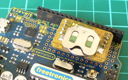
You can get MSGEQ7 ICs from various sources, however they had varying results. We now recommend using the neat module from Tronixlabs.

The circuit

The LED cube already has an Arduino Leonardo-compatible built in to the main PCB, so all you need to do is build a small circuit that contains the spectrum analyzer which connects to the I/O pins on the cube PCB and also has audio input and output connections. First, consider the schematic:

For the purposes of this project our spectrum analyser will only display the results from one channel of audio – if you want stereo, you’ll need two! And note that the strobe, reset and DCOUT pins on the MSGEQ7 are labelled with the connections to the cube PCB. Furthermore the pinouts for the MSGEQ7 don’t match the physical reality – here are the pinouts from the MSGEQ7 data sheet (.pdf):

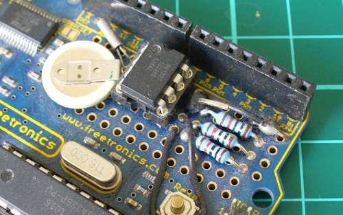
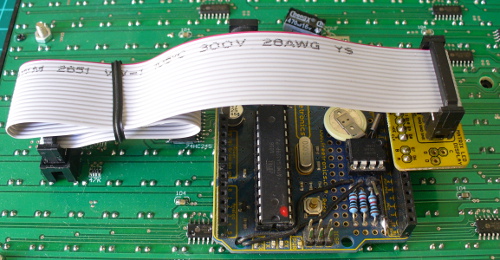
The circuit itself will be quite small and fit on a small amount of stripboard or veroboard. There is plenty of room underneath the cube to fit the circuit if so desired:

With a few moments you should be able to trace out your circuit to match the board type you have, remember to double-check before soldering. You will also need to connect the audio in point after the 1000 pF capacitor to a source of audio, and also pass it through so you can connect powered speakers, headphones, etc.

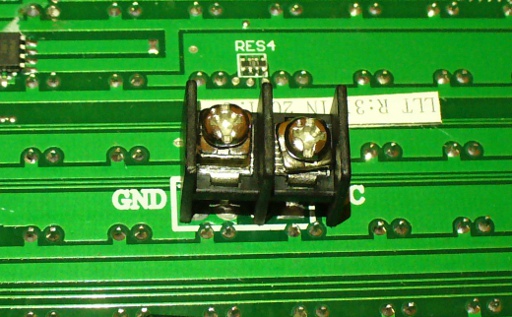
One method of doing so would be to cut up a male-female audio extension lead, and connect the shield to the GND of the circuit, and the signal line to the audio input on the circuit. Or if you have the parts handy and some shielded cable, just make your own input and output leads:

Be sure to test for shorts between the signal and shield before soldering to the circuit board. When finished, you should have something neat that you can hide under the cube or elsewhere:

Double-check your soldering for shorts and your board plan, then fit to the cube along with the audio source and speakers (etc).

Arduino Sketch

The sketch has two main functions – the first is to capture the levels from the MSGEQ7 and put the values for each frequency band into an array, and the second function is to turn on LEDs that represent the level for each band. If you’ve been paying attention you may be wondering how we can represent seven frequency bands with a 4x4x4 LED cube. Simple – by rotating the cube 45 degrees you can see seven vertical columns of LEDs:

So when looking from the angle as shown above, you have seven vertical columns, each with four levels of LEDs. Thus the strength of each frequency can be broken down into four levels, and then the appropriate LEDs turned on.

After this is done for each band, all the LEDs are turned off and the process repeats. For the sake of simplicity I’ve used the cube’s Arduino library to activate the LEDs, which also makes the sketch easier to fathom. The first example sketch only uses one colour:

// Freetronics CUBE4: and MSGEQ7 spectrum analyser
// MSGEQ7 strobe on A4, reset on D5, signal into A0

#include "SPI.h"
#include "Cube.h"
Cube cube;

int res = 5; // reset pins on D5
int left[7]; // store band values in these arrays
int band;

void setup()
{
  pinMode(res, OUTPUT); // reset
  pinMode(A4, OUTPUT); // strobe
  digitalWrite(res,LOW); 
  digitalWrite(A4,HIGH); 
  cube.begin(-1, 115200);
  Serial.begin(9600);
}

void readMSGEQ7()
// Function to read 7 band equalizers
{
  digitalWrite(res, HIGH);
  digitalWrite(res, LOW);
  for(band=0; band <7; band++)
  {
    digitalWrite(A4,LOW); // strobe pin on the shield - kicks the IC up to the next band 
    delayMicroseconds(30); // 
    left[band] = analogRead(0); // store band reading
    digitalWrite(A4,HIGH); 
  }
}

void loop()
{
  readMSGEQ7();

  for (band = 0; band < 7; band++)
  {
    // div each band strength into four layers, each band then one of the odd diagonals 

    // band one ~ 63 Hz
    if (left[0]>=768) { 
      cube.set(3,3,3, BLUE); 
    } 
    else       
      if (left[0]>=512) { 
      cube.set(3,3,2, BLUE); 
    } 
    else   
      if (left[0]>=256) { 
      cube.set(3,3,1, BLUE); 
    } 
    else       
      if (left[0]>=0) { 
      cube.set(3,3,0, BLUE); 
    } 

    // band two ~ 160 Hz
    if (left[1]>=768) 
    { 
      cube.set(3,2,3, BLUE); 
      cube.set(2,3,3, BLUE);      
    }  
    else
      if (left[1]>=512) 
      { 
        cube.set(3,2,2, BLUE); 
        cube.set(2,3,2, BLUE);      
      } 
      else   
        if (left[1]>=256) 
      { 
        cube.set(3,2,1, BLUE); 
        cube.set(2,3,1, BLUE);      
      } 
      else   
        if (left[1]>=0) 
      { 
        cube.set(3,2,0, BLUE); 
        cube.set(2,3,0, BLUE);      
      } 

    // band three ~ 400 Hz
    if (left[2]>=768) 
    { 
      cube.set(3,1,3, BLUE); 
      cube.set(2,2,3, BLUE);      
      cube.set(1,3,3, BLUE);            
    }  
    else
      if (left[2]>=512) 
      { 
        cube.set(3,1,2, BLUE); 
        cube.set(2,2,2, BLUE);      
        cube.set(1,3,2, BLUE);            
      } 
      else   
        if (left[2]>=256) 
      { 
        cube.set(3,1,1, BLUE); 
        cube.set(2,2,1, BLUE);      
        cube.set(1,3,1, BLUE);            
      } 
      else   
        if (left[2]>=0) 
      { 
        cube.set(3,1,0, BLUE); 
        cube.set(2,2,0, BLUE);      
        cube.set(1,3,0, BLUE);            
      } 

    // band four ~ 1 kHz
    if (left[3]>=768) 
    { 
      cube.set(3,0,3, BLUE); 
      cube.set(2,1,3, BLUE);      
      cube.set(1,2,3, BLUE);            
      cube.set(0,3,3, BLUE);                  
    }  
    else
      if (left[3]>=512) 
      { 
        cube.set(3,0,2, BLUE); 
        cube.set(2,1,2, BLUE);      
        cube.set(1,2,2, BLUE);            
        cube.set(0,3,2, BLUE);                        
      } 
      else   
        if (left[3]>=256) 
      { 
        cube.set(3,0,1, BLUE); 
        cube.set(2,1,1, BLUE);      
        cube.set(1,2,1, BLUE);      
        cube.set(0,3,1, BLUE);                        
      } 
      else   
        if (left[3]>=0) 
      { 
        cube.set(3,0,0, BLUE); 
        cube.set(2,1,0, BLUE);      
        cube.set(1,2,0, BLUE);            
        cube.set(0,3,0, BLUE);                        
      } 

    // band five  ~ 2.5 kHz
    if (left[4]>=768) 
    { 
      cube.set(2,0,3, BLUE); 
      cube.set(1,1,3, BLUE);      
      cube.set(0,2,3, BLUE);            
    }  
    else
      if (left[4]>=512) 
      { 
        cube.set(2,0,2, BLUE); 
        cube.set(1,1,2, BLUE);      
        cube.set(0,2,2, BLUE);            
      } 
      else   
        if (left[4]>=256) 
      { 
        cube.set(2,0,1, BLUE); 
        cube.set(1,1,1, BLUE);      
        cube.set(0,2,1, BLUE);      
      } 
      else   
        if (left[4]>=0) 
      { 
        cube.set(2,0,0, BLUE); 
        cube.set(1,1,0, BLUE);      
        cube.set(0,2,0, BLUE);            
      } 

    // band six   ~ 6.25 kHz
    if (left[5]>=768) 
    { 
      cube.set(1,0,3, BLUE); 
      cube.set(0,1,3, BLUE);      
    }  
    else
      if (left[5]>=512) 
      { 
        cube.set(1,0,2, BLUE); 
        cube.set(0,1,2, BLUE);      
      } 
      else   
        if (left[5]>=256) 
      { 
        cube.set(1,0,1, BLUE); 
        cube.set(0,1,1, BLUE);      
      } 
      else   
        if (left[5]>=0) 
      { 
        cube.set(1,0,0, BLUE); 
        cube.set(0,1,0, BLUE);      
      } 

    // band seven  ~ 16 kHz
    if (left[6]>=768) 
    { 
      cube.set(0,0,3, BLUE); 
    }  
    else
      if (left[6]>=512) 
      { 
        cube.set(0,0,2, BLUE); 
      } 
      else   
        if (left[6]>=256) 
      { 
        cube.set(0,0,1, BLUE); 
      } 
      else   
        if (left[6]>=0) 
      { 
        cube.set(0,0,0, BLUE); 
      } 
  }
  // now clear the CUBE, or if that's too slow - repeat the process but turn LEDs off
  cube.all(BLACK);
}

… and a quick video demonstration:

For a second example, we’ve used various colours:

// Freetronics CUBE4: and MSGEQ7 spectrum analyser
// MSGEQ7 strobe on A4, reset on D5, signal into A0
// now in colour!

#include "SPI.h"
#include "Cube.h"
Cube cube;

int res = 5; // reset pins on D5
int left[7]; // store band values in these arrays
int band;
int additional=0;

void setup()
{
  pinMode(res, OUTPUT); // reset
  pinMode(A4, OUTPUT); // strobe
  digitalWrite(res,LOW); 
  digitalWrite(A4,HIGH); 
  cube.begin(-1, 115200);
  Serial.begin(9600);
}

void readMSGEQ7()
// Function to read 7 band equalizers
{
  digitalWrite(res, HIGH);
  digitalWrite(res, LOW);
  for(band=0; band <7; band++)
  {
    digitalWrite(A4,LOW); // strobe pin on the shield - kicks the IC up to the next band 
    delayMicroseconds(30); // 
    left[band] = analogRead(0) + additional; // store band reading
    digitalWrite(A4,HIGH); 
  }
}

void loop()
{
  readMSGEQ7();

  for (band = 0; band < 7; band++)
  {
    // div each band strength into four layers, each band then one of the odd diagonals 

    // band one ~ 63 Hz
    if (left[0]>=768) { 
      cube.set(3,3,3, RED); 
    } 
    else       
      if (left[0]>=512) { 
      cube.set(3,3,2, YELLOW); 
    } 
    else   
      if (left[0]>=256) { 
      cube.set(3,3,1, YELLOW); 
    } 
    else       
      if (left[0]>=0) { 
      cube.set(3,3,0, BLUE); 
    } 

    // band two ~ 160 Hz
    if (left[1]>=768) 
    { 
      cube.set(3,2,3, RED); 
      cube.set(2,3,3, RED);      
    }  
    else
      if (left[1]>=512) 
      { 
        cube.set(3,2,2, YELLOW); 
        cube.set(2,3,2, YELLOW);      
      } 
      else   
        if (left[1]>=256) 
      { 
        cube.set(3,2,1, YELLOW); 
        cube.set(2,3,1, YELLOW);      
      } 
      else   
        if (left[1]>=0) 
      { 
        cube.set(3,2,0, BLUE); 
        cube.set(2,3,0, BLUE);      
      } 

    // band three ~ 400 Hz
    if (left[2]>=768) 
    { 
      cube.set(3,1,3, RED); 
      cube.set(2,2,3, RED);      
      cube.set(1,3,3, RED);            
    }  
    else
      if (left[2]>=512) 
      { 
        cube.set(3,1,2, YELLOW); 
        cube.set(2,2,2, YELLOW);      
        cube.set(1,3,2, YELLOW);            
      } 
      else   
        if (left[2]>=256) 
      { 
        cube.set(3,1,1, YELLOW); 
        cube.set(2,2,1, YELLOW);      
        cube.set(1,3,1, YELLOW);            
      } 
      else   
        if (left[2]>=0) 
      { 
        cube.set(3,1,0, BLUE); 
        cube.set(2,2,0, BLUE);      
        cube.set(1,3,0, BLUE);            
      } 

    // band four ~ 1 kHz
    if (left[3]>=768) 
    { 
      cube.set(3,0,3, RED); 
      cube.set(2,1,3, RED);      
      cube.set(1,2,3, RED);            
      cube.set(0,3,3, RED);                  
    }  
    else
      if (left[3]>=512) 
      { 
        cube.set(3,0,2, YELLOW); 
        cube.set(2,1,2, YELLOW);      
        cube.set(1,2,2, YELLOW);            
        cube.set(0,3,2, YELLOW);                        
      } 
      else   
        if (left[3]>=256) 
      { 
        cube.set(3,0,1, YELLOW); 
        cube.set(2,1,1, YELLOW);      
        cube.set(1,2,1, YELLOW);      
        cube.set(0,3,1, YELLOW);                        
      } 
      else   
        if (left[3]>=0) 
      { 
        cube.set(3,0,0, BLUE); 
        cube.set(2,1,0, BLUE);      
        cube.set(1,2,0, BLUE);            
        cube.set(0,3,0, BLUE);                        
      } 

    // band five  ~ 2.5 kHz
    if (left[4]>=768) 
    { 
      cube.set(2,0,3, RED); 
      cube.set(1,1,3, RED);      
      cube.set(0,2,3, RED);            
    }  
    else
      if (left[4]>=512) 
      { 
        cube.set(2,0,2, YELLOW); 
        cube.set(1,1,2, YELLOW);      
        cube.set(0,2,2, YELLOW);            
      } 
      else   
        if (left[4]>=256) 
      { 
        cube.set(2,0,1, YELLOW); 
        cube.set(1,1,1, YELLOW);      
        cube.set(0,2,1, YELLOW);      
      } 
      else   
        if (left[4]>=0) 
      { 
        cube.set(2,0,0, BLUE); 
        cube.set(1,1,0, BLUE);      
        cube.set(0,2,0, BLUE);            
      } 

    // band six   ~ 6.25 kHz
    if (left[5]>=768) 
    { 
      cube.set(1,0,3, RED); 
      cube.set(0,1,3, RED);      
    }  
    else
      if (left[5]>=512) 
      { 
        cube.set(1,0,2, YELLOW); 
        cube.set(0,1,2, YELLOW);      
      } 
      else   
        if (left[5]>=256) 
      { 
        cube.set(1,0,1, YELLOW); 
        cube.set(0,1,1, YELLOW);      
      } 
      else   
        if (left[5]>=0) 
      { 
        cube.set(1,0,0, BLUE); 
        cube.set(0,1,0, BLUE);      
      } 

    // band seven  ~ 16 kHz
    if (left[6]>=768) 
    { 
      cube.set(0,0,3, RED); 
    }  
    else
      if (left[6]>=512) 
      { 
        cube.set(0,0,2, YELLOW); 
      } 
      else   
        if (left[6]>=256) 
      { 
        cube.set(0,0,1, YELLOW); 
      } 
      else   
        if (left[6]>=0) 
      { 
        cube.set(0,0,0, BLUE); 
      } 
  }
  // now clear the CUBE, or if that's too slow - repeat the process but turn LEDs off
  cube.all(BLACK);
}

… and the second video demonstration:

A little bit of noise comes through into the spectrum analyser, most likely due to the fact that the entire thing is unshielded. The previous prototype used the Arduino shield from the tutorial which didn’t have this problem, so if you’re keen perhaps make your own custom PCB for this project.

xxxxxxx

Conclusion

Well that was something different and I hope you enjoyed it, and can find use for the circuit. That MSGEQ7 is a handy IC and with some imagination you can create a variety of musically-influenced displays. And if you enjoyed this article, or want to introduce someone else to the interesting world of Arduino – check out my book (now in a fourth printing!) “Arduino Workshop”.

Have fun and keep checking into tronixstuff.com. Why not follow things on twitterGoogle+, subscribe  for email updates or RSS using the links on the right-hand column, or join our forum – dedicated to the projects and related items on this website.

The post Project – LED Cube Spectrum Analyzer appeared first on tronixstuff.

Build an Arduino-controlled Larson Scanner

Introduction

For fun and a little bit of learning, let’s make a Larson Scanner. This isn’t a new project, for example we reviewed a kit in the past – however after finding some large LEDs we decided to make our own version. We’ll use an Arduino-compatible circuit to control the LEDs, and explain both the hardware and required Arduino sketch – then build a temporary small and a more permanent large version (and a bonus project).

So what is a Larson Scanner anyway? Named in honour of Glen A. Larson the creator of television shows such as Battlestar Galactica and Knight Rider – as this kit recreates the left and right blinking motion used in props from those television shows. For example:

Making your own is quite simple, it’s just eight LEDs or lamps blinking in a certain order. If you’re not familiar with the Arduino hardware, please have a quick review of this tutorial before continuing.

Small version

If you’re just interested in whipping up a solderless breadboard or small version, it will take less than fifteen minutes. Just get an Arduino Uno or compatible board and construct the following circuit (the resistors are 560Ω):

The sketch is also very simple. There are two ways to address those digital output pins, and to save sanity and clock cycles we’re going to use port manipulation instead of many digitalWrite() functions. So for our circuit above, enter and upload the following sketch:

// Simple Arduno LED back-and-forth effects, similar to "KITT" from "Knight Rider"
// Original idea by Glen A. Larson 
// Arduino sketch - John Boxall 2013

int del=75; // delay between LED movements

void setup()
{
  DDRD = B11111111; // D0~D7 outputs
}

void loop()
{
  PORTD = B00000001; 
  delay(del);
  PORTD = B00000011; 
  delay(del);
  PORTD = B00000111;   
  delay(del);
  PORTD = B00001110; 
  delay(del);  
  PORTD = B00011100; 
  delay(del);  
  PORTD = B00111000; 
  delay(del);  
  PORTD = B01110000; 
  delay(del);  
  PORTD = B11100000; 
  delay(del);  
  PORTD = B11000000; 
  delay(del);  
  PORTD = B10000000; 
  delay(del);  
  PORTD = B11000000; 
  delay(del);  
  PORTD = B11100000; 
  delay(del);  
  PORTD = B01110000;   
  delay(del);  
  PORTD = B00111000;   
  delay(del);  
  PORTD = B00011100;   
  delay(del);  
  PORTD = B00001110;   
  delay(del);  
  PORTD = B00000111;   
  delay(del);  
  PORTD = B00000011;   
  delay(del);  
}

Notice how the ones and zeros in the byte send to PORTD (digital pins 7~0) represent the “movement” of the scanner? You’d have to agree this is a better method of addressing the LEDs. Have some fun and experiment with the patterns you can generate and also the delay. In the following video we’ve quickly demonstrated the circuit on a solderless breadboard using different delay periods:

Large Version

Now to make something more permanent, and much larger. There are many ways of completing this project, so the following version will be a design narrative that you can follow to help with planning your own. The first consideration will be the LEDs you want to use. For our example we used some Kingbright DLC2-6SRD 20mm bright red versions we had in stock:

However you can use what you have available. The key to success will be driving the LEDs at their maximum brightness without damage. So you need to find out the best forward voltage and current for the LEDs, then do some basic mathematics. From our example LEDs’ data sheet, the maximum brightness is from 60 mA of current, at just under 6 V. A quick connection to a variable power supply shows the LEDs at this setting:

We can’t get this kind of brightness from our Arduino 5V circuit, so instead we’ll increase the circuit supply voltage to 9V and use resistors to reduce the current for the LEDs. To find the resistor value, use the following:

… where Vs is the supply voltage (9), VLED is the forward voltage for the LED (5.6), and ILED is the forward current (60 mA). The value for R is 56.66 Ω – however you can’t get that value, so 68 Ω will be the closest value from the supplier. Finally, the power of the resistor required (in watts) is calculated by W = VA. So W = 3.4 (voltage drop over resistor) * 0.06 = 0.204 W. So we’ll need 68 Ω 0.25 W resistors for our LEDs. Thus instead of running the LED straight off a digital output, it will be switched on and off via a simple BC548 transistor – shown in the following schematic example:

The digital output for each LED is connected to the 1k Ω resistor and thus switches the transistor on to allow the current to flow through the LED when required. This is repeated for each LED we intend to use – which for the case of our large scanner project is six. (Why six? Someone bought a board which was too narrow for eight…) Next is the Arduino-compatible circuit. Timing isn’t critical so we’ll save components by using a ceramic resonator instead of a crystal and two capacitors. And as shown below (note that although the image on the microcontroller says ATmega168, we’ll use an ATmega328P):

(If you’re not up for making your own Arduino-compatible circuit, there’s plenty of alternative small boards you can use such as the Nano or LeoStick). Although the symbol for Y1 (the resonator) looks complex, it’s just a resonator – for example:

the centre pin goes to GND and the outside pins go to XTAL1 and XTAL2 on the microcontroller. It isn’t polarised so either direction is fine.

At this point you may also want to consider how you’ll upload and update sketches on the project. One method is to mount the microcontroller in a socket, and just yank it between an Arduino board to upload the sketch, and then put it back in the project board. If you use this method then you’ll need a microcontroller with the Arduino bootloader.  However a more civilised method is to add ICSP header pins – they’re the 2 x 3 pins you see on most boards, for example:

With which you can use a USBASP programmer to connect your board directly to a computer just like a normal Arduino. Just use Ctrl-Shift-U to upload your sketch via the programmer. Furthermore you can use bare microcontrollers without the bootloader, as all the necessary code is included with the direct upload. So if this method interests you, add the following to your circuit:

The RESET pin is connected to pin 1 of the microcontroller. Speaking of which, if you’re unsure about which pins on the ATmega328P are which, a variety of suppliers have handy labels you can stick on top, for example:

At this point it’s time to put it all together. We’re using a random piece of prototyping PCB, and your final plan will depend on your board. As an aside, check out the Lochmaster stripboard planning software if you use stripboard a lot. As mentioned earlier your final schematic will vary depending on the number of LEDs, their requirements with respect to current and your choice of Arduino platform. By now you have the knowledge to plan the circuit yourself. After some work here’s our final board:

… and the scanner in action. We used the same sketch as for the temporary version – however reduce it to six outputs (D0~5) to match the LEDs.

 Bonus project – Electronic Die

What else can you do with six LEDs? Make an electronic die! Here’s a simple sketch that simply picks a random number every five seconds. The random number generator is seeded from unused an analogue input pin.

// Simple Arduno LED die using Larson Scanner hardware described in http://wp.me/p3LK05-36m 
// John Boxall 2013

int del=5000; // delay between new rolls
int num;

byte  digits[] = { B00000001, 
                   B00000010, 
                   B00000100, 
                   B00001000,
                   B00010000,
                   B00100000 };

void setup()
{
  randomSeed(analogRead(0)); // reseed the random number generator with some noise
  DDRD = B11111111; // D0~D7 outputs
}

void rollDie()
{
  for (int i = 0; i< 20; i++)
  {
    num = random(0,6);
    PORTD = digits[num];
    delay(50);
  }
}

void pickNumber()
{
  num = random(0,5);
  PORTD = digits[num];
  delay(1000);
}

void loop()
{
  rollDie();
  pickNumber();
}

And a quick video of our die in action:

Conclusion

We hope you found this interesting and at least made a temporary scanner on a breadboard – or at least learned something. Kudos if you went ahead and made a larger one. If you made a video, share it with us in the comments. And if you made it this far – check out my new book “Arduino Workshop” from No Starch Press.

In the meanwhile have fun and keep checking into tronixstuff.com. Why not follow things on twitterGoogle+, subscribe  for email updates or RSS using the links on the right-hand column? And join our friendly Google Group – dedicated to the projects and related items on this website. Sign up – it’s free, helpful to each other –  and we can all learn something.

The post Build an Arduino-controlled Larson Scanner appeared first on tronixstuff.

Tronixstuff 22 Aug 01:13

Bluetooth Android Processing 3

PART THREE


If you happened to land on this page and missed PART ONE, and PART TWO, I would advise you go back and read those sections first.

This is what you'll find in partone:
  • Downloading and setting up the Android SDK
  • Downloading the Processing IDE
  • Setting up and preparing the Android device
  • Running through a couple of Processing/Android sketches on an Andoid phone.
This is what you will find in part two:

  • Introducing Toasts (display messages)
  • Looking out for BluetoothDevices using BroadcastReceivers
  • Getting useful information from a discovered Bluetooth device
  • Connecting to a Bluetooth Device
  • An Arduino Bluetooth Sketch that can be used in this tutorial


InputStream and OutputStream
We will now borrow some code from the Android developers site to help us to establish communication between the Android phone and the Bluetooth shield on the Arduino. By this stage we have already scanned and discovered the bluetooth device and made a successful connection. We now need to create an InputStream and OutputStream to handle the flow of communication between the devices. Let us start with the Android/Processing Side.
The Android Developers site suggests to create a new Thread to handle the incoming and outgoing bytes, because this task uses "blocking" calls. Blocking calls means that the application will appear to be frozen until the call completes. We will create a new Thread to receive bytes through the BluetoothSocket's InputStream, and will send bytes to the Arduino through the BluetoothSocket's OutputStream.
This Thread will continue to listen/send bytes for as long as needed, and will eventually close when we tell it to. We will also need a Handler() to act on any bytes received via the InputStream. The Handler is necessary to transfer information from the IO Thread to the main application thread. This is done by using a Message class. Here is a summary of relevant code that we will subsequently add to the ConnectBluetooth sketch (which was described in Part Two of this tutorial):

 1
2
3
4
5
6
7
8
9
10
11
12
13
14
15
16
17
18
19
20
21
22
23
24
25
26
27
28
29
30
31
32
33
34
35
36
37
38
39
40
41
42
43
44
45
46
47
48
49
50
51
52
53
54
55
56
57
58
59
60
61
62
63
64
65
66
67
68
69
70
71
72
73
74
75
76
77
78
79
80
81
82
83
84
85
86
87
88
import android.bluetooth.BluetoothSocket;
import java.io.InputStream;
import java.io.OutputStream;
import android.os.Handler;
import android.os.Message;
import android.util.Log;

// Message types used by the Handler
public static final int MESSAGE_WRITE = 1;
public static final int MESSAGE_READ = 2;

// The Handler that gets information back from the Socket
private final Handler mHandler = new Handler() {
@Override
public void handleMessage(Message msg) {
switch (msg.what) {
case MESSAGE_WRITE:
//Do something when writing
break;
case MESSAGE_READ:
//Get the bytes from the msg.obj
byte[] readBuf = (byte[]) msg.obj;
// construct a string from the valid bytes in the buffer
String readMessage = new String(readBuf, 0, msg.arg1);
break;
}
}
};


private class SendReceiveBytes implements Runnable {
private BluetoothSocket btSocket;
private InputStream btInputStream = null;
private OutputStream btOutputStream = null;
String TAG = "SendReceiveBytes";

public SendReceiveBytes(BluetoothSocket socket) {
btSocket = socket;
try {
btInputStream = btSocket.getInputStream();
btOutputStream = btSocket.getOutputStream();
}
catch (IOException streamError) {
Log.e(TAG, "Error when getting input or output Stream");
}
}

public void run() {
byte[] buffer = new byte[1024]; // buffer store for the stream
int bytes; // bytes returned from read()

// Keep listening to the InputStream until an exception occurs
while (true) {
try {
// Read from the InputStream
bytes = btInputStream.read(buffer);
// Send the obtained bytes to the UI activity
mHandler.obtainMessage(MESSAGE_READ, bytes, -1, buffer)
.sendToTarget();
}
catch (IOException e) {
Log.e(TAG, "Error reading from btInputStream");
break;
}
}
}

/* Call this from the main activity to send data to the remote device */
public void write(byte[] bytes) {
try {
btOutputStream.write(bytes);
}
catch (IOException e) {
Log.e(TAG, "Error when writing to btOutputStream");
}
}

/* Call this from the main activity to shutdown the connection */
public void cancel() {
try {
btSocket.close();
}
catch (IOException e) {
Log.e(TAG, "Error when closing the btSocket");
}
}
}

Notice that we place an endless loop in the run() method to continuously read bytes from the InputStream. This continuous process of reading bytes needs to be a different thread from the main application otherwise it would cause the program to "hang". This thread passes any read bytes to the main application by using the Handler's .sendToTarget() method.
You will also notice the use of Log.e(TAG, ".....") commands. This is useful for debugging Android problems, especially when you comae across errors that generate a "caused the application to close unexpectedly" dialog box to appear on your phone.  I personally created a shortcut of the adb.exe on my desktop and changed the target to
  • "c:\[INSERT FOLDER]\Android\android-sdk\platform-tools\adb.exe" logcat *:E
The adb.exe program comes with the Android-SDK downloaded in Part One . Once you find the adb.exe on your hard-drive, you just create a shortcut on your desktop. Right-click the shortcut, choose "Properties" and as indicated above, you change the last bit of the Target to
  • logcat *:E
So if you get an unexpected error on your android device, just go back to your laptop, and double-click on your new desktop adb.exe shortcut to get a better idea of where your program has gone wrong.

We will now incorporate the sketch above into our ConnectBluetooth Android/Processing App, however we will call this updated version "SendReceiveBytes"
Once we have created a successful connection, and created our Input/OutputStreams, we will send a single letter "r" to the Arduino via bluetooth, and if all goes well, we should see the light on the RGB Chainable LED turn Red (see further down for Arduino sketch).
I borrowed Byron's code snippet from this site: to convert a string ("r") to a byte array, which is used in the write() method. The relevant code can be found on lines 199-208 below. I have bolded the lines numbers to make it a little easier to see the changes I made (compared to the previous sketch).

Android/Processing Sketch 6: SendReceiveBytes
 1
2
3
4
5
6
7
8
9
10
11
12
13
14
15
16
17
18
19
20
21
22
23
24
25
26
27
28
29
30
31
32
33
34
35
36
37
38
39
40
41
42
43
44
45
46
47
48
49
50
51
52
53
54
55
56
57
58
59
60
61
62
63
64
65
66
67
68
69
70
71
72
73
74
75
76
77
78
79
80
81
82
83
84
85
86
87
88
89
90
91
92
93
94
95
96
97
98
99
100
101
102
103
104
105
106
107
108
109
110
111
112
113
114
115
116
117
118
119
120
121
122
123
124
125
126
127
128
129
130
131
132
133
134
135
136
137
138
139
140
141
142
143
144
145
146
147
148
149
150
151
152
153
154
155
156
157
158
159
160
161
162
163
164
165
166
167
168
169
170
171
172
173
174
175
176
177
178
179
180
181
182
183
184
185
186
187
188
189
190
191
192
193
194
195
196
197
198
199
200
201
202
203
204
205
206
207
208
209
210
211
212
213
214
215
216
217
218
219
220
221
222
223
224
225
226
227
228
229
230
231
232
233
234
235
236
237
238
239
240
241
242
243
244
245
246
247
248
249
250
251
252
253
254
255
256
257
258
259
260
261
262
263
264
265
266
267
268
269
270
271
272
273
274
275
276
277
278
279
280
281
282
283
284
285
286
287
288
289
290
291
292
293
294
295
296
297
298
299
300
301
302
303
304
305
306
307
308
309
310
311
312
313
314
315
316
317
318
319
320
321
322
323
324
325
326
327
328
/* SendReceiveBytes: Written by ScottC on 25 March 2013 using 
Processing version 2.0b8
Tested on a Samsung Galaxy SII, with Android version 2.3.4
Android ADK - API 10 SDK platform */

import android.content.BroadcastReceiver;
import android.content.Context;
import android.content.Intent;
import android.content.IntentFilter;
import android.widget.Toast;
import android.view.Gravity;
import android.bluetooth.BluetoothAdapter;
import android.bluetooth.BluetoothDevice;

import java.util.UUID;
import java.io.IOException;
import java.io.InputStream;
import java.io.OutputStream;
import android.os.Handler;
import android.os.Message;
import android.util.Log;

import android.bluetooth.BluetoothServerSocket;
import android.bluetooth.BluetoothSocket;
public BluetoothSocket scSocket;


boolean foundDevice=false; //When true, the screen turns green.
boolean BTisConnected=false; //When true, the screen turns purple.
String serverName = "ArduinoBasicsServer";

// Message types used by the Handler
public static final int MESSAGE_WRITE = 1;
public static final int MESSAGE_READ = 2;
String readMessage="";

//Get the default Bluetooth adapter
BluetoothAdapter bluetooth = BluetoothAdapter.getDefaultAdapter();

/*The startActivityForResult() within setup() launches an
Activity which is used to request the user to turn Bluetooth on.
The following onActivityResult() method is called when this
Activity exits. */
@Override
protected void onActivityResult(int requestCode, int resultCode, Intent data) {
if (requestCode==0) {
if (resultCode == RESULT_OK) {
ToastMaster("Bluetooth has been switched ON");
}
else {
ToastMaster("You need to turn Bluetooth ON !!!");
}
}
}


/* Create a BroadcastReceiver that will later be used to
receive the names of Bluetooth devices in range. */
BroadcastReceiver myDiscoverer = new myOwnBroadcastReceiver();


/* Create a BroadcastReceiver that will later be used to
identify if the Bluetooth device is connected */
BroadcastReceiver checkIsConnected = new myOwnBroadcastReceiver();


// The Handler that gets information back from the Socket
private final Handler mHandler = new Handler() {
@Override
public void handleMessage(Message msg) {
switch (msg.what) {
case MESSAGE_WRITE:
//Do something when writing
break;
case MESSAGE_READ:
//Get the bytes from the msg.obj
byte[] readBuf = (byte[]) msg.obj;
// construct a string from the valid bytes in the buffer
readMessage = new String(readBuf, 0, msg.arg1);
break;
}
}
};


void setup() {
orientation(LANDSCAPE);
/*IF Bluetooth is NOT enabled, then ask user permission to enable it */
if (!bluetooth.isEnabled()) {
Intent requestBluetooth = new Intent(BluetoothAdapter.ACTION_REQUEST_ENABLE);
startActivityForResult(requestBluetooth, 0);
}


/*If Bluetooth is now enabled, then register a broadcastReceiver to report any
discovered Bluetooth devices, and then start discovering */
if (bluetooth.isEnabled()) {
registerReceiver(myDiscoverer, new IntentFilter(BluetoothDevice.ACTION_FOUND));
registerReceiver(checkIsConnected, new IntentFilter(BluetoothDevice.ACTION_ACL_CONNECTED));

//Start bluetooth discovery if it is not doing so already
if (!bluetooth.isDiscovering()) {
bluetooth.startDiscovery();
}
}
}


void draw() {
//Display a green screen if a device has been found,
//Display a purple screen when a connection is made to the device
if (foundDevice) {
if (BTisConnected) {
background(170, 50, 255); // purple screen
}
else {
background(10, 255, 10); // green screen
}
}

//Display anything received from Arduino
text(readMessage, 10, 10);
}


/* This BroadcastReceiver will display discovered Bluetooth devices */
public class myOwnBroadcastReceiver extends BroadcastReceiver {
ConnectToBluetooth connectBT;

@Override
public void onReceive(Context context, Intent intent) {
String action=intent.getAction();
ToastMaster("ACTION:" + action);

//Notification that BluetoothDevice is FOUND
if (BluetoothDevice.ACTION_FOUND.equals(action)) {
//Display the name of the discovered device
String discoveredDeviceName = intent.getStringExtra(BluetoothDevice.EXTRA_NAME);
ToastMaster("Discovered: " + discoveredDeviceName);

//Display more information about the discovered device
BluetoothDevice discoveredDevice = intent.getParcelableExtra(BluetoothDevice.EXTRA_DEVICE);
ToastMaster("getAddress() = " + discoveredDevice.getAddress());
ToastMaster("getName() = " + discoveredDevice.getName());

int bondyState=discoveredDevice.getBondState();
ToastMaster("getBondState() = " + bondyState);

String mybondState;
switch(bondyState) {
case 10:
mybondState="BOND_NONE";
break;
case 11:
mybondState="BOND_BONDING";
break;
case 12:
mybondState="BOND_BONDED";
break;
default:
mybondState="INVALID BOND STATE";
break;
}
ToastMaster("getBondState() = " + mybondState);

//Change foundDevice to true which will make the screen turn green
foundDevice=true;

//Connect to the discovered bluetooth device (SeeedBTSlave)
if (discoveredDeviceName.equals("SeeedBTSlave")) {
ToastMaster("Connecting you Now !!");
unregisterReceiver(myDiscoverer);
connectBT = new ConnectToBluetooth(discoveredDevice);
//Connect to the the device in a new thread
new Thread(connectBT).start();
}
}

//Notification if bluetooth device is connected
if (BluetoothDevice.ACTION_ACL_CONNECTED.equals(action)) {
ToastMaster("CONNECTED _ YAY");

while (scSocket==null) {
//do nothing
}
ToastMaster("scSocket" + scSocket);
BTisConnected=true; //turn screen purple
if (scSocket!=null) {
SendReceiveBytes sendReceiveBT = new SendReceiveBytes(scSocket);
new Thread(sendReceiveBT).start();
String red = "r";
byte[] myByte = stringToBytesUTFCustom(red);
sendReceiveBT.write(myByte);
}
}
}
}
public static byte[] stringToBytesUTFCustom(String str) {
char[] buffer = str.toCharArray();
byte[] b = new byte[buffer.length << 1];
for (int i = 0; i < buffer.length; i++) {
int bpos = i << 1;
b[bpos] = (byte) ((buffer[i]&0xFF00)>>8);
b[bpos + 1] = (byte) (buffer[i]&0x00FF);
}
return b;
}

public class ConnectToBluetooth implements Runnable {
private BluetoothDevice btShield;
private BluetoothSocket mySocket = null;
private UUID uuid = UUID.fromString("00001101-0000-1000-8000-00805F9B34FB");

public ConnectToBluetooth(BluetoothDevice bluetoothShield) {
btShield = bluetoothShield;
try {
mySocket = btShield.createRfcommSocketToServiceRecord(uuid);
}
catch(IOException createSocketException) {
//Problem with creating a socket
Log.e("ConnectToBluetooth", "Error with Socket");
}
}

@Override
public void run() {
/* Cancel discovery on Bluetooth Adapter to prevent slow connection */
bluetooth.cancelDiscovery();

try {
/*Connect to the bluetoothShield through the Socket. This will block
until it succeeds or throws an IOException */
mySocket.connect();
scSocket=mySocket;
}
catch (IOException connectException) {
Log.e("ConnectToBluetooth", "Error with Socket Connection");
try {
mySocket.close(); //try to close the socket
}
catch(IOException closeException) {
}
return;
}
}

/* Will cancel an in-progress connection, and close the socket */
public void cancel() {
try {
mySocket.close();
}
catch (IOException e) {
}
}
}


private class SendReceiveBytes implements Runnable {
private BluetoothSocket btSocket;
private InputStream btInputStream = null;
private OutputStream btOutputStream = null;
String TAG = "SendReceiveBytes";

public SendReceiveBytes(BluetoothSocket socket) {
btSocket = socket;
try {
btInputStream = btSocket.getInputStream();
btOutputStream = btSocket.getOutputStream();
}
catch (IOException streamError) {
Log.e(TAG, "Error when getting input or output Stream");
}
}


public void run() {
byte[] buffer = new byte[1024]; // buffer store for the stream
int bytes; // bytes returned from read()

// Keep listening to the InputStream until an exception occurs
while (true) {
try {
// Read from the InputStream
bytes = btInputStream.read(buffer);
// Send the obtained bytes to the UI activity
mHandler.obtainMessage(MESSAGE_READ, bytes, -1, buffer)
.sendToTarget();
}
catch (IOException e) {
Log.e(TAG, "Error reading from btInputStream");
break;
}
}
}


/* Call this from the main activity to send data to the remote device */
public void write(byte[] bytes) {
try {
btOutputStream.write(bytes);
}
catch (IOException e) {
Log.e(TAG, "Error when writing to btOutputStream");
}
}


/* Call this from the main activity to shutdown the connection */
public void cancel() {
try {
btSocket.close();
}
catch (IOException e) {
Log.e(TAG, "Error when closing the btSocket");
}
}
}


/* My ToastMaster function to display a messageBox on the screen */
void ToastMaster(String textToDisplay) {
Toast myMessage = Toast.makeText(getApplicationContext(),
textToDisplay,
Toast.LENGTH_SHORT);
myMessage.setGravity(Gravity.CENTER, 0, 0);
myMessage.show();
}


Arduino Sketch: Testing the Input/OutputStream
We will borrow the Arduino Sketch from my previous blog post (here). Which should change the RGB LED to red when it receives an "r" through the bluetooth serial port.
You should also be able to send text to the Android phone by opening up the Serial Monitor on the Arduino IDE (although found this to be somewhat unreliable/unpredictable. I may need to investigate a better way of doing this, but it should work to some capacity (I sometimes find that a couple of letters go missing on transmision).
In this sketch I am using a Bluetooth shield like this one,  and have connected a Grove Chainable RGB LED to it using a Grove Universal 4 Pin Cable.


Arduino Sketch 2: Bluetooth RGB Colour Changer

 1
2
3
4
5
6
7
8
9
10
11
12
13
14
15
16
17
18
19
20
21
22
23
24
25
26
27
28
29
30
31
32
33
34
35
36
37
38
39
40
41
42
43
44
45
46
47
48
49
50
51
52
53
54
55
56
57
58
59
60
61
62
63
64
65
66
67
68
69
70
71
72
73
74
75
76
77
78
79
80
81
82
83
84
85
86
87
88
89
90
91
92
93
94
95
96
97
98
99
100
101
102
103
104
105
106
107
108
109
110
111
112
113
114
115
116
117
118
119
120
121
122
123
124
125
126
127
128
129
130
131
132
133
134
135
136
137
138
139
140
141
142
143
144
145
146
147
148
149
/* This project combines the code from a few different sources.
This project was put together by ScottC on the 15/01/2013
http://arduinobasics.blogspot.com/

Bluetooth slave code by Steve Chang - downloaded from :
http://www.seeedstudio.com/wiki/index.php?title=Bluetooth_Shield

Grove Chainable RGB code can be found here :
http://www.seeedstudio.com/wiki/Grove_-_Chainable_RGB_LED#Introduction

*/

#include <SoftwareSerial.h> //Software Serial Port
#define uint8 unsigned char
#define uint16 unsigned int
#define uint32 unsigned long int

#define RxD 6 // This is the pin that the Bluetooth (BT_TX) will transmit to the Arduino (RxD)
#define TxD 7 // This is the pin that the Bluetooth (BT_RX) will receive from the Arduino (TxD)

#define DEBUG_ENABLED 1

int Clkpin = 9; //RGB LED Clock Pin (Digital 9)
int Datapin = 8; //RGB LED Data Pin (Digital 8)

SoftwareSerial blueToothSerial(RxD,TxD);
/*----------------------SETUP----------------------------*/ void setup() {
Serial.begin(9600); // Allow Serial communication via USB cable to computer (if required)
pinMode(RxD, INPUT); // Setup the Arduino to receive INPUT from the bluetooth shield on Digital Pin 6
pinMode(TxD, OUTPUT); // Setup the Arduino to send data (OUTPUT) to the bluetooth shield on Digital Pin 7
pinMode(13,OUTPUT); // Use onboard LED if required.
setupBlueToothConnection(); //Used to initialise the Bluetooth shield

pinMode(Datapin, OUTPUT); // Setup the RGB LED Data Pin
pinMode(Clkpin, OUTPUT); // Setup the RGB LED Clock pin

}
/*----------------------LOOP----------------------------*/ void loop() {
digitalWrite(13,LOW); //Turn off the onboard Arduino LED
char recvChar;
while(1){
if(blueToothSerial.available()){//check if there's any data sent from the remote bluetooth shield
recvChar = blueToothSerial.read();
Serial.print(recvChar); // Print the character received to the Serial Monitor (if required)

//If the character received = 'r' , then change the RGB led to display a RED colour
if(recvChar=='r'){
Send32Zero(); // begin
DataDealWithAndSend(255, 0, 0); // first node data
Send32Zero(); // send to update data
}

//If the character received = 'g' , then change the RGB led to display a GREEN colour
if(recvChar=='g'){
Send32Zero(); // begin
DataDealWithAndSend(0, 255, 0); // first node data
Send32Zero(); // send to update data
}

//If the character received = 'b' , then change the RGB led to display a BLUE colour
if(recvChar=='b'){
Send32Zero(); // begin
DataDealWithAndSend(0, 0, 255); // first node data
Send32Zero(); // send to update data
}
}

//You can use the following code to deal with any information coming from the Computer (serial monitor)
if(Serial.available()){
recvChar = Serial.read();

//This will send value obtained (recvChar) to the phone. The value will be displayed on the phone.
blueToothSerial.print(recvChar);
}
}
}

//The following code is necessary to setup the bluetooth shield ------copy and paste----------------
void setupBlueToothConnection()
{
blueToothSerial.begin(38400); //Set BluetoothBee BaudRate to default baud rate 38400
blueToothSerial.print("\r\n+STWMOD=0\r\n"); //set the bluetooth work in slave mode
blueToothSerial.print("\r\n+STNA=SeeedBTSlave\r\n"); //set the bluetooth name as "SeeedBTSlave"
blueToothSerial.print("\r\n+STOAUT=1\r\n"); // Permit Paired device to connect me
blueToothSerial.print("\r\n+STAUTO=0\r\n"); // Auto-connection should be forbidden here
delay(2000); // This delay is required.
blueToothSerial.print("\r\n+INQ=1\r\n"); //make the slave bluetooth inquirable
Serial.println("The slave bluetooth is inquirable!");
delay(2000); // This delay is required.
blueToothSerial.flush();
}

//The following code snippets are used update the colour of the RGB LED-----copy and paste------------
void ClkProduce(void){
digitalWrite(Clkpin, LOW);
delayMicroseconds(20);
digitalWrite(Clkpin, HIGH);
delayMicroseconds(20);
}
void Send32Zero(void){
unsigned char i;
for (i=0; i<32; i++){
digitalWrite(Datapin, LOW);
ClkProduce();
}
}

uint8 TakeAntiCode(uint8 dat){
uint8 tmp = 0;
if ((dat & 0x80) == 0){
tmp |= 0x02;
}

if ((dat & 0x40) == 0){
tmp |= 0x01;
}

return tmp;
}
// gray data
void DatSend(uint32 dx){
uint8 i;
for (i=0; i<32; i++){
if ((dx & 0x80000000) != 0){
digitalWrite(Datapin, HIGH);
} else {
digitalWrite(Datapin, LOW);
}

dx <<= 1;
ClkProduce();
}
}
// data processing
void DataDealWithAndSend(uint8 r, uint8 g, uint8 b){
uint32 dx = 0;

dx |= (uint32)0x03 << 30; // highest two bits 1,flag bits
dx |= (uint32)TakeAntiCode(b) << 28;
dx |= (uint32)TakeAntiCode(g) << 26;
dx |= (uint32)TakeAntiCode(r) << 24;

dx |= (uint32)b << 16;
dx |= (uint32)g << 8;
dx |= r;

DatSend(dx);
}


Some GUI Buttons

My aim is to somewhat recreate the experience from a similar project I blogged about (here). However I wanted to have much more control over the GUI. I will start by creating a few buttons, but will later look at making a much more fun/interactive design (hopefully). The following simple Android/Processing sketch will be totally independant of the sketch above, it will be a simple App that will have a few buttons which will change the colour of the background on the phone. Once we get the hang of this, we will incorporate it into our Bluetooth Sketch.
To start off with, we will need to download an Android/Processing library which will allow us to create the buttons that we will use in our App.
Unzip the apwidgets_r44.zip file and put the apwidgets folder into your default Processing sketch "libraries" folder. For more information about installing contributed libraries into you Processing IDE - have a look at this site.
You will need to reboot your Processing IDE before being able to see the "apwidgets" item appear in the Processing IDE's menu,
  • Sketch > Import Library :  Under the "Contributed" list item.
If you cannot see this menu item, then you will need to try again. Make sure you are putting it into the default sketch libraries folder, which may not be in the same folder as the processing IDE. To find out the default sketch location - look here:
  • File > Preferences > Sketchbook location
Ok, now that you have the APWidgets library installed in your Processing IDE, make sure you are still in Andorid Mode, and copy the following sketch into the IDE, and run the program on your device. This sketch borrows heavily from the APWidgets Button example, which can be found here.

Android/Processing Sketch 7: Button Presser
 1
2
3
4
5
6
7
8
9
10
11
12
13
14
15
16
17
18
19
20
21
22
23
24
25
26
27
28
29
30
31
32
33
34
35
36
37
38
39
40
41
42
43
44
45
46
47
48
49
50
51
52
53
54
55
import apwidgets.*;

APWidgetContainer widgetContainer;
APButton redButton, greenButton, blueButton, offButton;
String buttonText="";
int buttonWidth=0;
int buttonHeight=0;
int n=4; //number of buttons
int gap=10; //gap between buttons


void setup() {
buttonWidth=((width/n)-(n*gap));
buttonHeight=(height/2);
widgetContainer = new APWidgetContainer(this); //create new container for widgets
redButton =new APButton((buttonWidth*(n-4)+(gap*1)), gap, buttonWidth, buttonHeight, "RED"); //Create a RED button
greenButton = new APButton((buttonWidth*(n-3)+(gap*2)), gap, buttonWidth, buttonHeight, "GREEN"); //Create a GREEN button
blueButton = new APButton((buttonWidth*(n-2)+(gap*3)), gap, buttonWidth, buttonHeight, "BLUE"); //Create a BLUE button
offButton = new APButton((buttonWidth*(n-1)+(gap*4)), gap, buttonWidth, buttonHeight, "OFF"); //Create a OFF button
widgetContainer.addWidget(redButton); //place red button in container
widgetContainer.addWidget(greenButton); //place green button in container
widgetContainer.addWidget(blueButton);//place blue button in container
widgetContainer.addWidget(offButton);//place off button in container
background(0); //Start with a black background
}


void draw() {
//Change the text based on the button being pressed.
text(buttonText, 10, buttonHeight+(buttonHeight/2));
}


//onClickWidget is called when a widget is clicked/touched
void onClickWidget(APWidget widget) {

if (widget == redButton) { //if the red button was clicked
buttonText="RED";
background(255, 0, 0);
}
else if (widget == greenButton) { //if the green button was clicked
buttonText="GREEN";
background(0, 255, 0);
}
else if (widget == blueButton) { //if the blue button was clicked
buttonText="BLUE";
background(0, 0, 255);
}
else if (widget == offButton) { //if the off button was clicked
buttonText="OFF";
background(0);
}
}

The sketch creates 4 buttons, one for Red, Green, Blue and Off. In this example, we use the onClickWidget() method to deal with button_click events, which we use to change the colour of the background.  I forgot to include the following line in the setup() method:
  • orientation(LANDSCAPE);
This will force the application to go into landscape mode, which is what I intended.


Bluetooth Buttons : Adding Buttons to the Bluetooth project

We will now incorporate the Buttons sketch into our Bluetooth project so that when we press a button, it will send a letter to the Arduino via Bluetooth. The letter will be used by the Arduino to decide what colour to display on the Chainable RGB LED. We will still keep the previous functionality of changing the LED to RED when a successful Input/OutputStream is created, because this will be the signal to suggest that it is now ok to press the buttons (and we should see it work).

Here is the updated Android/Processing sketch

Android/Processing Sketch 8: Bluetooth App1

 1
2
3
4
5
6
7
8
9
10
11
12
13
14
15
16
17
18
19
20
21
22
23
24
25
26
27
28
29
30
31
32
33
34
35
36
37
38
39
40
41
42
43
44
45
46
47
48
49
50
51
52
53
54
55
56
57
58
59
60
61
62
63
64
65
66
67
68
69
70
71
72
73
74
75
76
77
78
79
80
81
82
83
84
85
86
87
88
89
90
91
92
93
94
95
96
97
98
99
100
101
102
103
104
105
106
107
108
109
110
111
112
113
114
115
116
117
118
119
120
121
122
123
124
125
126
127
128
129
130
131
132
133
134
135
136
137
138
139
140
141
142
143
144
145
146
147
148
149
150
151
152
153
154
155
156
157
158
159
160
161
162
163
164
165
166
167
168
169
170
171
172
173
174
175
176
177
178
179
180
181
182
183
184
185
186
187
188
189
190
191
192
193
194
195
196
197
198
199
200
201
202
203
204
205
206
207
208
209
210
211
212
213
214
215
216
217
218
219
220
221
222
223
224
225
226
227
228
229
230
231
232
233
234
235
236
237
238
239
240
241
242
243
244
245
246
247
248
249
250
251
252
253
254
255
256
257
258
259
260
261
262
263
264
265
266
267
268
269
270
271
272
273
274
275
276
277
278
279
280
281
282
283
284
285
286
287
288
289
290
291
292
293
294
295
296
297
298
299
300
301
302
303
304
305
306
307
308
309
310
311
312
313
314
315
316
317
318
319
320
321
322
323
324
325
326
327
328
329
330
331
332
333
334
335
336
337
338
339
340
341
342
343
344
345
346
347
348
349
350
351
352
353
354
355
356
357
358
359
360
361
362
363
364
365
366
367
368
369
370
371
372
373
374
375
376
377
378
379
380
381
382
383
384
385
386
387
388
389
390
391
392
393
394
395
396
397
398
399
400
401
402
403
404
/* BluetoothApp1: Written by ScottC on 25 March 2013 using 
Processing version 2.0b8
Tested on a Samsung Galaxy SII, with Android version 2.3.4
Android ADK - API 10 SDK platform
Apwidgets version: r44 */

import android.content.BroadcastReceiver;
import android.content.Context;
import android.content.Intent;
import android.content.IntentFilter;
import android.widget.Toast;
import android.view.Gravity;
import android.bluetooth.BluetoothAdapter;
import android.bluetooth.BluetoothDevice;

import java.util.UUID;
import java.io.IOException;
import java.io.InputStream;
import java.io.OutputStream;
import android.os.Handler;
import android.os.Message;
import android.util.Log;

import android.bluetooth.BluetoothServerSocket;
import android.bluetooth.BluetoothSocket;
import apwidgets.*;
public BluetoothSocket scSocket;


//Used for the GUI**************************************
APWidgetContainer widgetContainer;
APButton redButton, greenButton, blueButton, offButton;
String buttonText="";
int buttonWidth=0;
int buttonHeight=0;
int n=4; //number of buttons
int gap=10; //gap between buttons

boolean foundDevice=false; //When true, the screen turns green.
boolean BTisConnected=false; //When true, the screen turns purple.
String serverName = "ArduinoBasicsServer";

// Message types used by the Handler
public static final int MESSAGE_WRITE = 1;
public static final int MESSAGE_READ = 2;
String readMessage="";

//Used to send bytes to the Arduino
SendReceiveBytes sendReceiveBT=null;

//Get the default Bluetooth adapter
BluetoothAdapter bluetooth = BluetoothAdapter.getDefaultAdapter();

/*The startActivityForResult() within setup() launches an
Activity which is used to request the user to turn Bluetooth on.
The following onActivityResult() method is called when this
Activity exits. */
@Override
protected void onActivityResult(int requestCode, int resultCode, Intent data) {
if (requestCode==0) {
if (resultCode == RESULT_OK) {
ToastMaster("Bluetooth has been switched ON");
}
else {
ToastMaster("You need to turn Bluetooth ON !!!");
}
}
}


/* Create a BroadcastReceiver that will later be used to
receive the names of Bluetooth devices in range. */
BroadcastReceiver myDiscoverer = new myOwnBroadcastReceiver();


/* Create a BroadcastReceiver that will later be used to
identify if the Bluetooth device is connected */
BroadcastReceiver checkIsConnected = new myOwnBroadcastReceiver();


// The Handler that gets information back from the Socket
private final Handler mHandler = new Handler() {
@Override
public void handleMessage(Message msg) {
switch (msg.what) {
case MESSAGE_WRITE:
//Do something when writing
break;
case MESSAGE_READ:
//Get the bytes from the msg.obj
byte[] readBuf = (byte[]) msg.obj;
// construct a string from the valid bytes in the buffer
readMessage = new String(readBuf, 0, msg.arg1);
break;
}
}
};


void setup() {
orientation(LANDSCAPE);

//Setup GUI********************************
buttonWidth=((width/n)-(n*gap));
buttonHeight=(height/2);
widgetContainer = new APWidgetContainer(this); //create new container for widgets
redButton =new APButton((buttonWidth*(n-4)+(gap*1)), gap, buttonWidth, buttonHeight, "RED"); //Create a RED button
greenButton = new APButton((buttonWidth*(n-3)+(gap*2)), gap, buttonWidth, buttonHeight, "GREEN"); //Create a GREEN button
blueButton = new APButton((buttonWidth*(n-2)+(gap*3)), gap, buttonWidth, buttonHeight, "BLUE"); //Create a BLUE button
offButton = new APButton((buttonWidth*(n-1)+(gap*4)), gap, buttonWidth, buttonHeight, "OFF"); //Create a OFF button
widgetContainer.addWidget(redButton); //place red button in container
widgetContainer.addWidget(greenButton); //place green button in container
widgetContainer.addWidget(blueButton);//place blue button in container
widgetContainer.addWidget(offButton);//place off button in container
background(0); //Start with a black background

/*IF Bluetooth is NOT enabled, then ask user permission to enable it */
if (!bluetooth.isEnabled()) {
Intent requestBluetooth = new Intent(BluetoothAdapter.ACTION_REQUEST_ENABLE);
startActivityForResult(requestBluetooth, 0);
}

/*If Bluetooth is now enabled, then register a broadcastReceiver to report any
discovered Bluetooth devices, and then start discovering */
if (bluetooth.isEnabled()) {
registerReceiver(myDiscoverer, new IntentFilter(BluetoothDevice.ACTION_FOUND));
registerReceiver(checkIsConnected, new IntentFilter(BluetoothDevice.ACTION_ACL_CONNECTED));

//Start bluetooth discovery if it is not doing so already
if (!bluetooth.isDiscovering()) {
bluetooth.startDiscovery();
}
}
}


void draw() {
//Display a green screen if a device has been found,
//Display a purple screen when a connection is made to the device
if (foundDevice) {
if (BTisConnected) {
background(170, 50, 255); // purple screen
}
else {
background(10, 255, 10); // green screen
}
}


//Change the text based on the button being pressed.
text(buttonText, 10, buttonHeight+(buttonHeight/2));

//Display anything received from Arduino
text(readMessage, 10, buttonHeight+(buttonHeight/2)+30);
}


/* This BroadcastReceiver will display discovered Bluetooth devices */
public class myOwnBroadcastReceiver extends BroadcastReceiver {
ConnectToBluetooth connectBT;

@Override
public void onReceive(Context context, Intent intent) {
String action=intent.getAction();
ToastMaster("ACTION:" + action);

//Notification that BluetoothDevice is FOUND
if (BluetoothDevice.ACTION_FOUND.equals(action)) {
//Display the name of the discovered device
String discoveredDeviceName = intent.getStringExtra(BluetoothDevice.EXTRA_NAME);
ToastMaster("Discovered: " + discoveredDeviceName);

//Display more information about the discovered device
BluetoothDevice discoveredDevice = intent.getParcelableExtra(BluetoothDevice.EXTRA_DEVICE);
ToastMaster("getAddress() = " + discoveredDevice.getAddress());
ToastMaster("getName() = " + discoveredDevice.getName());

int bondyState=discoveredDevice.getBondState();
ToastMaster("getBondState() = " + bondyState);

String mybondState;
switch(bondyState) {
case 10:
mybondState="BOND_NONE";
break;
case 11:
mybondState="BOND_BONDING";
break;
case 12:
mybondState="BOND_BONDED";
break;
default:
mybondState="INVALID BOND STATE";
break;
}
ToastMaster("getBondState() = " + mybondState);

//Change foundDevice to true which will make the screen turn green
foundDevice=true;

//Connect to the discovered bluetooth device (SeeedBTSlave)
if (discoveredDeviceName.equals("SeeedBTSlave")) {
ToastMaster("Connecting you Now !!");
unregisterReceiver(myDiscoverer);
connectBT = new ConnectToBluetooth(discoveredDevice);
//Connect to the the device in a new thread
new Thread(connectBT).start();
}
}

//Notification if bluetooth device is connected
if (BluetoothDevice.ACTION_ACL_CONNECTED.equals(action)) {
ToastMaster("CONNECTED _ YAY");
int counter=0;
while (scSocket==null) {
//do nothing
}
ToastMaster("scSocket" + scSocket);
BTisConnected=true; //turn screen purple
if (scSocket!=null) {
sendReceiveBT = new SendReceiveBytes(scSocket);
new Thread(sendReceiveBT).start();
String red = "r";
byte[] myByte = stringToBytesUTFCustom(red);
sendReceiveBT.write(myByte);
}
}
}
}

public static byte[] stringToBytesUTFCustom(String str) {
char[] buffer = str.toCharArray();
byte[] b = new byte[buffer.length << 1];
for (int i = 0; i < buffer.length; i++) {
int bpos = i << 1;
b[bpos] = (byte) ((buffer[i]&0xFF00)>>8);
b[bpos + 1] = (byte) (buffer[i]&0x00FF);
}
return b;
}

public class ConnectToBluetooth implements Runnable {
private BluetoothDevice btShield;
private BluetoothSocket mySocket = null;
private UUID uuid = UUID.fromString("00001101-0000-1000-8000-00805F9B34FB");

public ConnectToBluetooth(BluetoothDevice bluetoothShield) {
btShield = bluetoothShield;
try {
mySocket = btShield.createRfcommSocketToServiceRecord(uuid);
}
catch(IOException createSocketException) {
//Problem with creating a socket
Log.e("ConnectToBluetooth", "Error with Socket");
}
}

@Override
public void run() {
/* Cancel discovery on Bluetooth Adapter to prevent slow connection */
bluetooth.cancelDiscovery();

try {
/*Connect to the bluetoothShield through the Socket. This will block
until it succeeds or throws an IOException */
mySocket.connect();
scSocket=mySocket;
}
catch (IOException connectException) {
Log.e("ConnectToBluetooth", "Error with Socket Connection");
try {
mySocket.close(); //try to close the socket
}
catch(IOException closeException) {
}
return;
}
}

// Will allow you to get the socket from this class
public BluetoothSocket getSocket() {
return mySocket;
}

/* Will cancel an in-progress connection, and close the socket */
public void cancel() {
try {
mySocket.close();
}
catch (IOException e) {
}
}
}


private class SendReceiveBytes implements Runnable {
private BluetoothSocket btSocket;
private InputStream btInputStream = null;
;
private OutputStream btOutputStream = null;
String TAG = "SendReceiveBytes";

public SendReceiveBytes(BluetoothSocket socket) {
btSocket = socket;
try {
btInputStream = btSocket.getInputStream();
btOutputStream = btSocket.getOutputStream();
}
catch (IOException streamError) {
Log.e(TAG, "Error when getting input or output Stream");
}
}

public void run() {
byte[] buffer = new byte[1024]; // buffer store for the stream
int bytes; // bytes returned from read()

// Keep listening to the InputStream until an exception occurs
while (true) {
try {
// Read from the InputStream
bytes = btInputStream.read(buffer);
// Send the obtained bytes to the UI activity
mHandler.obtainMessage(MESSAGE_READ, bytes, -1, buffer)
.sendToTarget();
}
catch (IOException e) {
Log.e(TAG, "Error reading from btInputStream");
break;
}
}
}

/* Call this from the main activity to send data to the remote device */
public void write(byte[] bytes) {
try {
btOutputStream.write(bytes);
}
catch (IOException e) {
Log.e(TAG, "Error when writing to btOutputStream");
}
}

/* Call this from the main activity to shutdown the connection */
public void cancel() {
try {
btSocket.close();
}
catch (IOException e) {
Log.e(TAG, "Error when closing the btSocket");
}
}
}


/* My ToastMaster function to display a messageBox on the screen */
void ToastMaster(String textToDisplay) {
Toast myMessage = Toast.makeText(getApplicationContext(),
textToDisplay,
Toast.LENGTH_SHORT);
myMessage.setGravity(Gravity.CENTER, 0, 0);
myMessage.show();
}


//onClickWidget is called when a widget is clicked/touched
void onClickWidget(APWidget widget) {
String sendLetter = "";

//Disable the previous Background colour changers
foundDevice=false;
BTisConnected=false;

if (widget == redButton) { //if the red button was clicked
buttonText="RED";
background(255, 0, 0);
sendLetter = "r";
}
else if (widget == greenButton) { //if the green button was clicked
buttonText="GREEN";
background(0, 255, 0);
sendLetter = "g";
}
else if (widget == blueButton) { //if the blue button was clicked
buttonText="BLUE";
background(0, 0, 255);
sendLetter = "b";
}
else if (widget == offButton) { //if the off button was clicked
buttonText="OFF";
background(0);
sendLetter = "x";
}

byte[] myByte = stringToBytesUTFCustom(sendLetter);
sendReceiveBT.write(myByte);
}
The sketch above has been thrown together without much planning or consideration for code efficiency. It was deliberately done this way so that you could see and follow the incremental approach used to create this Android/Processing Bluetooth App. I will do my best to rewrite and simplify some of the code, however, I don't anticipate the final sketch will be a short script.
You should have noticed that I included a fourth button called an "off" button. This will turn off the RGB led. However, the Arduino code in its current format does not know what to do with an 'x'. So we will update the sketch as follows:

Arduino Sketch 3: Bluetooth RGB Colour Changer (with OFF option)

 1
2
3
4
5
6
7
8
9
10
11
12
13
14
15
16
17
18
19
20
21
22
23
24
25
26
27
28
29
30
31
32
33
34
35
36
37
38
39
40
41
42
43
44
45
46
47
48
49
50
51
52
53
54
55
56
57
58
59
60
61
62
63
64
65
66
67
68
69
70
71
72
73
74
75
76
77
78
79
80
81
82
83
84
85
86
87
88
89
90
91
92
93
94
95
96
97
98
99
100
101
102
103
104
105
106
107
108
109
110
111
112
113
114
115
116
117
118
119
120
121
122
123
124
125
126
127
128
129
130
131
132
133
134
135
136
137
138
139
140
141
142
143
144
145
146
147
148
149
150
151
152
153
154
155
156
157
158
159
160
161
162
163
164
165
166
167
168
169
170
/* This project combines the code from a few different sources.
This project was put together by ScottC on the 15/01/2013
http://arduinobasics.blogspot.com/

Bluetooth slave code by Steve Chang - downloaded from :
http://www.seeedstudio.com/wiki/index.php?title=Bluetooth_Shield

Grove Chainable RGB code can be found here :
http://www.seeedstudio.com/wiki/Grove_-_Chainable_RGB_LED#Introduction

Updated on 25 March 2013: Receive 'x' to turn off RGB LED.

*/

#include <SoftwareSerial.h> //Software Serial Port

#define uint8 unsigned char
#define uint16 unsigned int
#define uint32 unsigned long int

#define RxD 6 // This is the pin that the Bluetooth (BT_TX) will transmit to the Arduino (RxD)
#define TxD 7 // This is the pin that the Bluetooth (BT_RX) will receive from the Arduino (TxD)

#define DEBUG_ENABLED 1

int Clkpin = 9; //RGB LED Clock Pin (Digital 9)
int Datapin = 8; //RGB LED Data Pin (Digital 8)

SoftwareSerial blueToothSerial(RxD, TxD);


/*----------------------SETUP----------------------------*/
void setup() {
Serial.begin(9600); // Allow Serial communication via USB cable to computer (if required)
pinMode(RxD, INPUT); // Setup the Arduino to receive INPUT from the bluetooth shield on Digital Pin 6
pinMode(TxD, OUTPUT); // Setup the Arduino to send data (OUTPUT) to the bluetooth shield on Digital Pin 7
pinMode(13, OUTPUT); // Use onboard LED if required.
setupBlueToothConnection(); //Used to initialise the Bluetooth shield

pinMode(Datapin, OUTPUT); // Setup the RGB LED Data Pin
pinMode(Clkpin, OUTPUT); // Setup the RGB LED Clock pin
}


/*----------------------LOOP----------------------------*/
void loop() {
digitalWrite(13, LOW); //Turn off the onboard Arduino LED
char recvChar;
while (1) {
if (blueToothSerial.available()) {//check if there's any data sent from the remote bluetooth shield
recvChar = blueToothSerial.read();
Serial.print(recvChar); // Print the character received to the Serial Monitor (if required)

//If the character received = 'r' , then change the RGB led to display a RED colour
if (recvChar=='r') {
Send32Zero(); // begin
DataDealWithAndSend(255, 0, 0); // first node data
Send32Zero(); // send to update data
}

//If the character received = 'g' , then change the RGB led to display a GREEN colour
if (recvChar=='g') {
Send32Zero(); // begin
DataDealWithAndSend(0, 255, 0); // first node data
Send32Zero(); // send to update data
}

//If the character received = 'b' , then change the RGB led to display a BLUE colour
if (recvChar=='b') {
Send32Zero(); // begin
DataDealWithAndSend(0, 0, 255); // first node data
Send32Zero(); // send to update data
}

//If the character received = 'x' , then turn RGB led OFF
if (recvChar=='x') {
Send32Zero(); // begin
DataDealWithAndSend(0, 0, 0); // first node data
Send32Zero(); // send to update data
}
}

//You can use the following code to deal with any information coming from the Computer (serial monitor)
if (Serial.available()) {
recvChar = Serial.read();

//This will send value obtained (recvChar) to the phone. The value will be displayed on the phone.
blueToothSerial.print(recvChar);
}
}
}


//The following code is necessary to setup the bluetooth shield ------copy and paste----------------
void setupBlueToothConnection()
{
blueToothSerial.begin(38400); //Set BluetoothBee BaudRate to default baud rate 38400
blueToothSerial.print("\r\n+STWMOD=0\r\n"); //set the bluetooth work in slave mode
blueToothSerial.print("\r\n+STNA=SeeedBTSlave\r\n"); //set the bluetooth name as "SeeedBTSlave"
blueToothSerial.print("\r\n+STOAUT=1\r\n"); // Permit Paired device to connect me
blueToothSerial.print("\r\n+STAUTO=0\r\n"); // Auto-connection should be forbidden here
delay(2000); // This delay is required.
blueToothSerial.print("\r\n+INQ=1\r\n"); //make the slave bluetooth inquirable
Serial.println("The slave bluetooth is inquirable!");
delay(2000); // This delay is required.
blueToothSerial.flush();
}


//The following code snippets are used update the colour of the RGB LED-----copy and paste------------
void ClkProduce(void) {
digitalWrite(Clkpin, LOW);
delayMicroseconds(20);
digitalWrite(Clkpin, HIGH);
delayMicroseconds(20);
}
void Send32Zero(void) {
unsigned char i;
for (i=0; i<32; i++) {
digitalWrite(Datapin, LOW);
ClkProduce();
}
}


uint8 TakeAntiCode(uint8 dat) {
uint8 tmp = 0;
if ((dat & 0x80) == 0) {
tmp |= 0x02;
}

if ((dat & 0x40) == 0) {
tmp |= 0x01;
}
return tmp;
}


// gray data
void DatSend(uint32 dx) {
uint8 i;
for (i=0; i<32; i++) {
if ((dx & 0x80000000) != 0) {
digitalWrite(Datapin, HIGH);
}
else {
digitalWrite(Datapin, LOW);
}
dx <<= 1;
ClkProduce();
}
}

// data processing
void DataDealWithAndSend(uint8 r, uint8 g, uint8 b) {
uint32 dx = 0;

dx |= (uint32)0x03 << 30; // highest two bits 1,flag bits
dx |= (uint32)TakeAntiCode(b) << 28;
dx |= (uint32)TakeAntiCode(g) << 26;
dx |= (uint32)TakeAntiCode(r) << 24;

dx |= (uint32)b << 16;
dx |= (uint32)g << 8;
dx |= r;

DatSend(dx);
}


Well that concludes part 3.
Part 4 is a summary of the finished project with videos, screenshots, parts used etc.
I hope you found this tutorial useful. I would love to receive any advice on how I could improve these tutorials (please put your recommendations in comments below).

Reason for this Project:
While there are quite a few people creating Android/Arduino projects, I have not been able to find many that show how these are being accomplished using the Android/Processing IDE, and even less on how they are using Bluetooth in their Android/Processing projects. I hope my piecing of information will spark some creative Bluetooth projects of your own.


PART 4: Navigate here.


Bluetooth Android Processing 2

PART TWO


If you happened to land on this page and missed PART ONE, I would advise you go back and read that section first. You may get lost coming in half way through the story. This is what you'll find in part one.
  • Downloading and setting up the Android SDK
  • Downloading the Processing IDE
  • Setting up and preparing the Android device
  • Running through a couple of Processing/Android sketches on an Andoid phone.
In the last sketch we checked to see if Bluetooth was enabled, if not, we then asked for permission to turn it on. The screen would then display a different colour depending on the Bluetooth state. So let's keep on going,


ToastMaster - the master of all Toasts

I will now introduce you to Toast. What does "Toast" have to do with programming ? Toast is used by Android to quietly display little messages on the screen.
Have a look here for a a quick introduction to Toast, otherwise have a look at the Android Developers Toast information.

I will be creating my own method that relies on Toast to make the process of displaying messages easier. I have named this method: "ToastMaster".
A word of warning. Calling ToastMaster from within setup() will cause errorsin the DiscoverBluetooth sketch (further down this page).
This will not happen in every sketch, but the Discoverbluetooth sketch has subActivities which may cause some sort of conflict.. I did warn you.

Here is a quick look at my ToastMaster method (no need to compile this code):
1
2
3
4
5
6
7
8
/* My ToastMaster function to display a messageBox on the screen */
void ToastMaster(String textToDisplay){
Toast myMessage = Toast.makeText(getApplicationContext(),
textToDisplay,
Toast.LENGTH_LONG);
myMessage.setGravity(Gravity.CENTER, 0, 0);
myMessage.show();
}

Here is a breakdown of what this is doing:
  • Toast.makeText() - is used to construct the message to be displayed. 
  • getApplicationContext() - gets a handle on the Application
  • textToDisplay - is obvious, this is the text you want to display.
  • Toast.LENGTH_LONG - is how long you want the message to displayed for. (or LENGTH_SHORT)
  • setGravity() - sets the message position on the screen, in this case I have chosen to center the text.
  • show() - is used to actually show the message.

Broadcast Receivers : Looking out for Bluetooth devices
To listen/look out for any Bluetooth devices that are within range, we need to create and  register a Broadcast receiver.
When registering a BroadcastReceiver, you will need to tell the program what it is you are looking / listening out for. In our case we want to listen out for occasions whereby a Bluetooth device is FOUND.  This is represented by:
If a BluetoothDevice is found, then the designated BroadcastReceiver will be called. We make our own BroadcastReceiver in order to perform a task such as displaying the name of the discovered device on the phone. However, before you will find anything, you have to start Discovering. This is done by calling the startDiscovery() method of the default Bluetooth adapter.

Here are the relevant components:
1
2
3
4
5
6
7
8
9
10
11
12
13
14
15
16
17
18
19
20
21
22
23
24
25
BluetoothAdapter bluetooth = BluetoothAdapter.getDefaultAdapter();
BroadcastReceiver myDiscoverer =
new myOwnBroadcastReceiver();
//Within Setup()
if (bluetooth.isEnabled()) {
registerReceiver(myDiscoverer,
new IntentFilter(BluetoothDevice.ACTION_FOUND));
if (!bluetooth.isDiscovering()){
bluetooth.startDiscovery();
}
}

/* This BroadcastReceiver will display discovered Bluetooth devices */
public class myOwnBroadcastReceiver extends BroadcastReceiver {
@Override
public void onReceive(Context context, Intent intent) {
String discoveredDeviceName = intent.getStringExtra(BluetoothDevice.EXTRA_NAME);

//Display the name of the discovered device
ToastMaster("
Discovered: " + discoveredDeviceName);
}
}


Discovering Bluetooth devices: putting it all together

You will notice that in the following sketch, we have to import a whole lot more. Which is why I have tried to break it down into bite size chunks, to help you digest it all. Now we will put it all together into a sketch which will
  • ask to turn Bluetooth ON if it happens to be disabled.
  • If you don't turn on Bluetooth, it will tell you that you need to turn it on.
  • If you turn on bluetooth (or if it was already on), it will try to discover any bluetooth devices in range. These devices need to be made "discoverable" before running this sketch.
  • If the phone finds a bluetooth device, it will display the name of the device and will change the background screen colour to GREEN.
Android/Processing Sketch 4: DiscoverBluetooth
1
2
3
4
5
6
7
8
9
10
11
12
13
14
15
16
17
18
19
20
21
22
23
24
25
26
27
28
29
30
31
32
33
34
35
36
37
38
39
40
41
42
43
44
45
46
47
48
49
50
51
52
53
54
55
56
57
58
59
60
61
62
63
64
65
66
67
68
69
70
71
72
73
74
75
76
77
78
79
80
81
82
83
84
85
86
87
88
89
90
91
92
93
94
95
96
97
/* DiscoverBluetooth: Written by ScottC on 18 March 2013 using 
Processing version 2.0b8
Tested on a Samsung Galaxy SII, with Android version 2.3.4
Android ADK - API 10 SDK platform */


import android.content.BroadcastReceiver;
import android.content.Context;
import android.content.Intent;
import android.content.IntentFilter;
import android.widget.Toast;
import android.view.Gravity;
import android.bluetooth.BluetoothAdapter;
import android.bluetooth.BluetoothDevice;

boolean foundDevice=
false; //When this is true, the screen turns green.
//Get the default Bluetooth adapter
BluetoothAdapter bluetooth = BluetoothAdapter.getDefaultAdapter();

/*The startActivityForResult() within setup() launches an
Activity which is used to request the user to turn Bluetooth on.
The following onActivityResult() method is called when this
Activity exits. */

@Override
protected void onActivityResult(int requestCode, int resultCode, Intent data){
if(requestCode==0){
if(resultCode == RESULT_OK){
ToastMaster("
Bluetooth has been switched ON");
}
else {
ToastMaster("
You need to turn Bluetooth ON !!!");
}
}
}


/* Create a Broadcast Receiver that will later be used to
receive the names of Bluetooth devices in range. */

BroadcastReceiver myDiscoverer =
new myOwnBroadcastReceiver();


void setup(){
orientation(LANDSCAPE);
/*IF Bluetooth is NOT enabled, then ask user permission to enable it */
if (!bluetooth.isEnabled()) {
Intent requestBluetooth =
new Intent(BluetoothAdapter.ACTION_REQUEST_ENABLE);
startActivityForResult(requestBluetooth, 0);
}

/*If Bluetooth is now enabled, then register a broadcastReceiver to report any
discovered Bluetooth devices, and then start discovering */

if (bluetooth.isEnabled()) {
registerReceiver(myDiscoverer,
new IntentFilter(BluetoothDevice.ACTION_FOUND));
//Start bluetooth discovery if it is not doing so already
if (!bluetooth.isDiscovering()){
bluetooth.startDiscovery();
}
}
}


void draw(){
//Display a green screen if a device has been found
if(foundDevice){
background(10,255,10);
}
}


/* This BroadcastReceiver will display discovered Bluetooth devices */
public class myOwnBroadcastReceiver extends BroadcastReceiver {
@Override
public void onReceive(Context context, Intent intent) {
String discoveredDeviceName = intent.getStringExtra(BluetoothDevice.EXTRA_NAME);

//Display the name of the discovered device
ToastMaster("
Discovered: " + discoveredDeviceName);

//Change foundDevice to true which will make the screen turn green
foundDevice=
true;
}
}


/* My ToastMaster function to display a messageBox on the screen */
void ToastMaster(String textToDisplay){
Toast myMessage = Toast.makeText(getApplicationContext(),
textToDisplay,
Toast.LENGTH_LONG);
myMessage.setGravity(Gravity.CENTER, 0, 0);
myMessage.show();
}


Upgrading the Broadcast Receiver : More Device info

Ok, we have the device name. But what other information can we collect from the device? You can call
This will return the discovered BluetoothDevice, which can then be probed to find the following information.
  • .getName()   =  Which is a different way of getting the name of the BluetoothDevice.
  • .getAddress() = Returns the hardware address of the BluetoothDevice.  eg. "00:11:22:AA:BB:CC"
  • .getBondState() = Returns an integer which describes the BondState of the BluetoothDevice
These are the three possible BondStates 
Here is an updated version of the custom BroadcastReceiver class (myOwnBroadcastReceiver) from the DiscoverBluetooth sketch described above.
1
2
3
4
5
6
7
8
9
10
11
12
13
14
15
16
17
18
19
20
21
22
23
24
25
26
27
28
29
30
31
32
33
34
/* This BroadcastReceiver will display discovered Bluetooth devices */
public class myOwnBroadcastReceiver extends BroadcastReceiver {
@Override
public void onReceive(Context context, Intent intent) {

//Display the name of the discovered device
String discoveredDeviceName = intent.getStringExtra(BluetoothDevice.EXTRA_NAME);
ToastMaster("
Discovered: " + discoveredDeviceName);

//Display more information about the discovered device
BluetoothDevice discoveredDevice = intent.getParcelableExtra(BluetoothDevice.EXTRA_DEVICE);
ToastMaster("
getAddress() = " + discoveredDevice.getAddress());
ToastMaster("
getName() = " + discoveredDevice.getName());

int bondyState=discoveredDevice.getBondState();
ToastMaster("
getBondState() = " + bondyState);

String mybondState;
switch(bondyState){
case 10: mybondState="BOND_NONE";
break;
case 11: mybondState="BOND_BONDING";
break;
case 12: mybondState="BOND_BONDED";
break;
default: mybondState="INVALID BOND STATE";
break;
}
ToastMaster("
getBondState() = " + mybondState);

//Change foundDevice to true which will make the screen turn green
foundDevice=
true;
}
}

If you replace the old version of  myOwnBroadcastReceiver with this one, you will know a little bit more about the devices discovered.


Connecting to the Bluetooth Device:
While we now have more information about the Bluetooth device, we don't really need it, and we will get rid of it by the end of the tutorial, however we will keep it here for the time being. In the next updated sketch we will be making a connection to the discovered device, and turning the background purple when the connection is made. In order to do this we will need to
  • Create a boolean variable to hold the connection status
  • Create and register a new BroadcastReceiver to notify us when a connection broadcast action has been received.
  • Create a new thread to handle the connection
  • Change the background screen colour when a successful connection has been made
First we need the boolean to hold the connection status:
  • boolean BTisConnected=false;
When the boolean is true, the screen will change to purple. The draw() method will be updated to accommodate this requirement.
Next we will create and register a new BroadcastReceiver, it is created using this:
  • BroadcastReceiver checkIsConnected = new myOwnBroadcastReceiver();
This broadcastreceiver will be used to notify us when a connection has been made. Therefore we need to register the (BluetoothDevice.ACTION_ACL_CONNECTED)
action with the BroadcastReceiver in the following way
  • registerReceiver(checkIsConnected, new IntentFilter(BluetoothDevice.ACTION_ACL_CONNECTED));
We will need to update myOwnBroadcastReceiver() to be able to differentiate beween this action and the (BluetoothDevice.ACTION_FOUND) action used already. This is done by first getting the action from the intent variable described in the onReceive() method within myOwnBroadcastReceiver().
  • String action=intent.getAction();
We can differentiate the two actions using the following simplified code in myOwnBroadcastReceiver:

1
2
3
4
5
6
7
8
9
10
11
12
13
14
15
16
public class myOwnBroadcastReceiver extends BroadcastReceiver {
@Override
public void onReceive(Context context, Intent intent) {
String action=intent.getAction();

//Notification that BluetoothDevice is FOUND
if(BluetoothDevice.ACTION_FOUND.equals(action)){
foundDevice=
true; //Change the screen to green
}

//Notification if bluetooth device is connected
if(BluetoothDevice.ACTION_ACL_CONNECTED.equals(action)){
BTisConnected=
true; //turn screen purple
}
}
}

Now that we can be notified about the connection made to the Bluetooth Device, lets go through the code required to make the connection. We will only connect if we have actually discovered a device, so we will put this code within the FOUND section of myOwnBroadcastReceiver.

1
2
3
4
5
6
7
8
 //Connect to the discovered bluetooth device (SeeedBTSlave)
if(discoveredDeviceName.equals("SeeedBTSlave")){
unregisterReceiver(myDiscoverer);
ConnectToBluetooth connectBT =
new ConnectToBluetooth(discoveredDevice);
//Connect to the the device in a new thread
new Thread(connectBT).start();
}
}

We use the discoveredDeviceName variable to specifically target the Bluetooth device we wish to connect to. We then unregister the myDiscoverer BroadcastReceiver because we are going to stop discovering before we connect to the Bluetooth Device, plus if you don't, it will generate an error. We then pass our discovered device to a new Thread to connect to that device in the background.  The class used to handle the connection is the "ConnectToBluetooth" class as displayed below:

We will cancelDiscovery() on the bluetooth Adapter to prevent a slow connection.
Also we will need to use a specific UUID as per below:
  • private UUID uuid = UUID.fromString("00001101-0000-1000-8000-00805F9B34FB");
I have tried changing the UUID, but changing it to a different number prevented it from establishing a connection.
Before you can connect to the Bluetooth shield you need to use the UUID to create a BluetoothSocket.
  • mySocket = btShield.createRfcommSocketToServiceRecord(uuid);
Once you have the socket, you can then try to connect using:
  • mySocket.connect();
Make sure you have some way of closing the socket, this is done in the cancel() method.

1
2
3
4
5
6
7
8
9
10
11
12
13
14
15
16
17
18
19
20
21
22
23
24
25
26
27
28
29
30
31
32
33
34
35
36
37
38
39
40
public class ConnectToBluetooth implements Runnable{
private BluetoothDevice btShield;
private BluetoothSocket mySocket = null;
private UUID uuid = UUID.fromString("00001101-0000-1000-8000-00805F9B34FB");

public ConnectToBluetooth(BluetoothDevice bluetoothShield) {
btShield = bluetoothShield;
try{
mySocket = btShield.createRfcommSocketToServiceRecord(uuid);
}
catch(IOException createSocketException){
//Problem with creating a socket
}
}

@Override
public void run() {
/* Cancel discovery on Bluetooth Adapter to prevent slow connection */
bluetooth.cancelDiscovery();

try{
/*Connect to the bluetoothShield through the Socket. This will block
until it succeeds or throws an IOException */

mySocket.connect();
}
catch (IOException connectException){
try{
mySocket.close();
//try to close the socket
}
catch(IOException closeException){
}
return;
}
}

/* Will cancel an in-progress connection, and close the socket */
public void cancel() {
try {
mySocket.close();
}
catch (IOException e){
}
}
}

The major structure of this code was made possible using the following site:
http://jayxie.com/mirrors/android-sdk/guide/topics/wireless/bluetooth.html

And the following sites were also useful in getting some of the information I needed:
http://stackoverflow.com/questions/13238600/use-registerreceiver-for-non-activity-and-non-service-class
http://developer.android.com/guide/topics/connectivity/bluetooth.html


While I have described all the major components required to connect to the Bluetooth Device, I will now put it all together in a new and updated version of the "DiscoverBluetooth" Android/Processing sketch and call it "ConnectBluetooth". There is some additional code in this sketch which I did not specifically go through, for example, the code used to turn the background to purple in the draw() method. Look out for that one. Anyway, read through the following code, and make sure that you understand what each section is doing.

Android/Processing Sketch 5: ConnectBluetooth
1
2
3
4
5
6
7
8
9
10
11
12
13
14
15
16
17
18
19
20
21
22
23
24
25
26
27
28
29
30
31
32
33
34
35
36
37
38
39
40
41
42
43
44
45
46
47
48
49
50
51
52
53
54
55
56
57
58
59
60
61
62
63
64
65
66
67
68
69
70
71
72
73
74
75
76
77
78
79
80
81
82
83
84
85
86
87
88
89
90
91
92
93
94
95
96
97
98
99
100
101
102
103
104
105
106
107
108
109
110
111
112
113
114
115
116
117
118
119
120
121
122
123
124
125
126
127
128
129
130
131
132
133
134
135
136
137
138
139
140
141
142
143
144
145
146
147
148
149
150
151
152
153
154
155
156
157
158
159
160
161
162
163
164
165
166
167
168
169
170
171
172
173
174
175
176
177
178
179
180
181
182
183
184
185
186
187
188
189
190
191
192
193
194
195
196
197
198
199
200
/* ConnectBluetooth: Written by ScottC on 18 March 2013 using 
Processing version 2.0b8
Tested on a Samsung Galaxy SII, with Android version 2.3.4
Android ADK - API 10 SDK platform */


import android.content.BroadcastReceiver;
import android.content.Context;
import android.content.Intent;
import android.content.IntentFilter;
import android.widget.Toast;
import android.view.Gravity;
import android.bluetooth.BluetoothAdapter;
import android.bluetooth.BluetoothDevice;

import java.util.UUID;
import java.io.IOException;
import java.io.InputStream;
import java.io.OutputStream;
import android.util.Log;

import android.bluetooth.BluetoothServerSocket;
import android.bluetooth.BluetoothSocket;

boolean foundDevice=
false; //When true, the screen turns green.
boolean BTisConnected=
false; //When true, the screen turns purple.


//Get the default Bluetooth adapter
BluetoothAdapter bluetooth = BluetoothAdapter.getDefaultAdapter();

/*The startActivityForResult() within setup() launches an
Activity which is used to request the user to turn Bluetooth on.
The following onActivityResult() method is called when this
Activity exits. */

@Override
protected void onActivityResult(int requestCode, int resultCode, Intent data){
if(requestCode==0){
if(resultCode == RESULT_OK){
ToastMaster("
Bluetooth has been switched ON");
}
else {
ToastMaster("
You need to turn Bluetooth ON !!!");
}
}
}


/* Create a BroadcastReceiver that will later be used to
receive the names of Bluetooth devices in range. */

BroadcastReceiver myDiscoverer =
new myOwnBroadcastReceiver();
/* Create a BroadcastReceiver that will later be used to
identify if the Bluetooth device is connected */

BroadcastReceiver checkIsConnected =
new myOwnBroadcastReceiver();

void setup(){
orientation(LANDSCAPE);
/*IF Bluetooth is NOT enabled, then ask user permission to enable it */
if (!bluetooth.isEnabled()) {
Intent requestBluetooth =
new Intent(BluetoothAdapter.ACTION_REQUEST_ENABLE);
startActivityForResult(requestBluetooth, 0);
}

/*If Bluetooth is now enabled, then register a broadcastReceiver to report any
discovered Bluetooth devices, and then start discovering */

if (bluetooth.isEnabled()) {
registerReceiver(myDiscoverer,
new IntentFilter(BluetoothDevice.ACTION_FOUND));
registerReceiver(checkIsConnected,
new IntentFilter(BluetoothDevice.ACTION_ACL_CONNECTED));

//Start bluetooth discovery if it is not doing so already
if (!bluetooth.isDiscovering()){
bluetooth.startDiscovery();
}
}
}


void draw(){
//Display a green screen if a device has been found,
//Display a purple screen when a connection is made to the device
if(foundDevice){
if(BTisConnected){
background(170,50,255);
// purple screen
}
else {
background(10,255,10);
// green screen
}
}
}


/* This BroadcastReceiver will display discovered Bluetooth devices */
public class myOwnBroadcastReceiver extends BroadcastReceiver {
@Override
public void onReceive(Context context, Intent intent) {
String action=intent.getAction();
ToastMaster("
ACTION:" + action);

//Notification that BluetoothDevice is FOUND
if(BluetoothDevice.ACTION_FOUND.equals(action)){
//Display the name of the discovered device
String discoveredDeviceName = intent.getStringExtra(BluetoothDevice.EXTRA_NAME);
ToastMaster("
Discovered: " + discoveredDeviceName);

//Display more information about the discovered device
BluetoothDevice discoveredDevice = intent.getParcelableExtra(BluetoothDevice.EXTRA_DEVICE);
ToastMaster("
getAddress() = " + discoveredDevice.getAddress());
ToastMaster("
getName() = " + discoveredDevice.getName());

int bondyState=discoveredDevice.getBondState();
ToastMaster("
getBondState() = " + bondyState);

String mybondState;
switch(bondyState){
case 10: mybondState="BOND_NONE";
break;
case 11: mybondState="BOND_BONDING";
break;
case 12: mybondState="BOND_BONDED";
break;
default: mybondState="INVALID BOND STATE";
break;
}
ToastMaster("
getBondState() = " + mybondState);

//Change foundDevice to true which will make the screen turn green
foundDevice=
true;

//Connect to the discovered bluetooth device (SeeedBTSlave)
if(discoveredDeviceName.equals("SeeedBTSlave")){
ToastMaster("
Connecting you Now !!");
unregisterReceiver(myDiscoverer);
ConnectToBluetooth connectBT =
new ConnectToBluetooth(discoveredDevice);
//Connect to the the device in a new thread
new Thread(connectBT).start();
}
}

//Notification if bluetooth device is connected
if(BluetoothDevice.ACTION_ACL_CONNECTED.equals(action)){
ToastMaster("
CONNECTED _ YAY");
BTisConnected=
true; //turn screen purple
}
}
}
public class ConnectToBluetooth implements Runnable{
private BluetoothDevice btShield;
private BluetoothSocket mySocket = null;
private UUID uuid = UUID.fromString("00001101-0000-1000-8000-00805F9B34FB");

public ConnectToBluetooth(BluetoothDevice bluetoothShield) {
btShield = bluetoothShield;
try{
mySocket = btShield.createRfcommSocketToServiceRecord(uuid);
}
catch(IOException createSocketException){
//Problem with creating a socket
}
}

@Override
public void run() {
/* Cancel discovery on Bluetooth Adapter to prevent slow connection */
bluetooth.cancelDiscovery();

try{
/*Connect to the bluetoothShield through the Socket. This will block
until it succeeds or throws an IOException */

mySocket.connect();
}
catch (IOException connectException){
try{
mySocket.close();
//try to close the socket
}
catch(IOException closeException){
}
return;
}
}

/* Will cancel an in-progress connection, and close the socket */
public void cancel() {
try {
mySocket.close();
}
catch (IOException e){
}
}
}

/* My ToastMaster function to display a messageBox on the screen */
void ToastMaster(String textToDisplay){
Toast myMessage = Toast.makeText(getApplicationContext(),
textToDisplay,
Toast.LENGTH_SHORT);
myMessage.setGravity(Gravity.CENTER, 0, 0);
myMessage.show();
}


The Arduino Sketch

Most of the Android/Processing code used so far has depended on a Bluetooth Device being discoverable. Our ultimate aim it to connect to a Bluetooth Shield on an Arduino UNO or compatible board such as the Freetronics Eleven. The following sketch was essentially taken from one of my previous posts (here), however, I have stripped it down to the bear essentials so that it will only be discoverable, and will not send or receive data. I will provide this functionality later. I just wanted to show you the essential bits to establish the connection to the Shield.

ARDUINO Sketch 1: Bluetooth Pair and Connect
1
2
3
4
5
6
7
8
9
10
11
12
13
14
15
16
17
18
19
20
21
22
23
24
25
26
27
28
29
30
31
32
33
34
35
36
37
38
39
40
41
42
43
44
45
46
47
48
49
50
51
52
53
/* This project combines the code from a few different sources.
This project was put together by ScottC on the 22/03/2013
http://arduinobasics.blogspot.com/

Bluetooth slave code by Steve Chang - downloaded from :
http://www.seeedstudio.com/wiki/index.php?title=Bluetooth_Shield

This sketch does nothing more than setup bluetooth
connection capabilities. It does not send or receive data.

*/


#include <SoftwareSerial.h>
//Software Serial Port

#define RxD 6
// This is the pin that the Bluetooth (BT_TX) will transmit to the Arduino (RxD)
#define TxD 7
// This is the pin that the Bluetooth (BT_RX) will receive from the Arduino (TxD)

#define DEBUG_ENABLED 1

SoftwareSerial blueToothSerial(RxD,TxD);
/*----------------------SETUP----------------------------*/ void setup() {
Serial.begin(9600);
// Allow Serial communication via USB cable to computer (if required)
pinMode(RxD, INPUT);
// Setup the Arduino to receive INPUT from the bluetooth shield on Digital Pin 6
pinMode(TxD, OUTPUT);
// Setup the Arduino to send data (OUTPUT) to the bluetooth shield on Digital Pin 7
pinMode(13,OUTPUT);
// Use onboard LED if required.
setupBlueToothConnection();
//Used to initialise the Bluetooth shield
}
/*----------------------LOOP----------------------------*/ void loop() {
digitalWrite(13,LOW);
//Turn off the onboard Arduino LED
}

//The following code is necessary to setup the bluetooth shield ------copy and paste----------------
void setupBlueToothConnection()
{
blueToothSerial.begin(38400);
//Set BluetoothBee BaudRate to default baud rate 38400
blueToothSerial.print("
\r\n+STWMOD=0\r\n"); //set the bluetooth work in slave mode
blueToothSerial.print("
\r\n+STNA=SeeedBTSlave\r\n"); //set the bluetooth name as "SeeedBTSlave"
blueToothSerial.print("
\r\n+STOAUT=1\r\n"); // Permit Paired device to connect me
blueToothSerial.print("
\r\n+STAUTO=0\r\n"); // Auto-connection should be forbidden here
delay(2000);
// This delay is required.
blueToothSerial.print("
\r\n+INQ=1\r\n"); //make the slave bluetooth inquirable
Serial.println("
The slave bluetooth is inquirable!");
delay(2000);
// This delay is required.
blueToothSerial.flush();
}


Please make sure to setup the Bluetooth jumpers as per the picture below, otherwise you will not have much luck with the sketch above.


Well that brings us to the end of part TWO.

PART THREE
In part three we will attempt to actually send some data from the Android phone to the Arduino via Bluetooth, and vice versa. This will be when the real fun starts.


or GO BACK
Click on the link if you missed PART ONE

Bluetooth Android Processing 1


PART ONE


Introduction

This is a four part tutorial which will take you through step-by-step on how to create Android apps on your Mobile device that will allow you to communicate with your Arduino over Bluetooth. This tutorial is based upon the Windows environment and an Android device like the Samsung Galaxy S2 Phone.
I will take you through setting up your computer and phone, and will move through in stages so that you understand what each part of the bluetooth code is actually doing. Obviously you will need to ensure that you have a Bluetooth Shield on your Arduino to be able to walk through this tutorial with me.
If you are not interested in the step-by-step instructions, you can jump straight to the end (Part 4) which will have the complete Arduino and Android/Processing code that was used in the following video:

The Goal of this project (Video)


Setting up Processing for Android applications:
For the latest and most up to date version, please follow the instructions on this website: http://wiki.processing.org/w/Android

    Step One:
    Download the Android SDK from this website:
    http://developer.android.com/sdk/index.html

    Android SDK Download:
    Make sure to select the "Use and Existing IDE" link, as per the picture below.


    When you select the "Use an Existing IDE" link, it will then show you the appropriate download to use. This is what it should look like.

    Select the "Download the SDK Tools for Windows" link.
    Once you have downloaded the Android SDK, go ahead and install it as per the instructions below.
    These instruction can also be found here.


    Installing the necessary packages in the Android SDK Manager program
    Make the following 3 selections:
    • Tools: Android SDK Platform-tools
    • API 10: SDK Platform
    • Extras: Google USB Driver
    Then select the button on the bottom-right to install your selections.

    Here is a picture of the Android SDK Manager selections:


    While you may decide to download other packages,
    you MUST download API 10: SDK Platform .
    Do not leave this one out !!


    Step Two: Processing Download

    Download the latest Processing IDE(version 2.0 Beta 8) from this website:
    http://processing.org/download/

    I am using Windows 7, and have chosen to download the Windows 32 bit version as shown below.


    Load Processing, and switch to Android mode, as per the image below.


    You should now have an empty sketch window which looks something like this.


    Step Three: Setting up the Android Hardware device (Phone)
    For the latest steps you can have a look at this site:
    http://developer.android.com/tools/device.html

    However, these are the ones that I carried out:

    Turn on USB debugging on your Android Phone:
    To find out what Android Version you are on, have a look at
        Settings > About Phone : look for heading "Android Version".
    • My Android version is 2.3.4 on my Samsung Galaxy S2.
    To Enable USB Debugging:
       
    Settings > Applications > Development > Select (or Enable) USB debugging

      For those of you who have a different Android version, have a look below:


      Downloading the USB driver for your Android Phone(Windows Users)
      If you are developing on Windows and would like to connect an Android-powered device to test your applications, then you need to install the appropriate USB driver. Have a look at this site for more information on how to download the USB driver for your phone:
      http://developer.android.com/tools/extras/oem-usb.html

      I have a Samsung Galaxy S2 phone, so I had to go to the Samsung Site here:
      http://www.samsung.com/us/support/downloads

      But because I am not in the USA, I had to click on the link for "non-US products":
      http://www.samsung.com/us/support/downloads/global

      You will need the model number of your phone:
      On the Samsung Galaxy S2, you can go into
          Settings > About Phone => Model number. Otherwise, it is located behind the battery.
      • My Phone's Model Number is: GT-I9100
      See the image below for the link to press if you have a non-US phone.


      Then I continued with the install of the USB driver as per the document below:
      http://developer.android.com/tools/extras/oem-usb.html


      Step Four: Android-Processing Sketch
      We will now test our our current setup and make sure that we can run a simple Processing Sketch on the Phone. Bluetooth functionality will be tested later on, so all we need for this step, is our computer, our Android phone, and a USB cable. While it is possible to run this sketch without an Android phone (by using the emulator), I personally do not have the patience to wait an eternity while the emulator boots up... (yes, it takes an eternity)... In this tutorial, we are going to test it on the device (phone).
      This sketch has an orange background and a black circle which you can move around the screen with your finger (that's it) - I did say it was going to be a simple sketch.

      Copy and paste the following Android-Processing sketch into the IDE, and then press the (Run on Device) button, which is the triangle button or press Ctrl-R.


      Android/Processing Sketch 1: Circle Dragger

      1
      2
      3
      4
      5
      6
      7
      8
      9
      10
      11
      12
      13
      14
      15
      /*Circle Dragger: Simple Android-Processing Sketch written by ScottC on 13/03/2013.
      Visit: http://arduinobasics.blogspot.com/
      */

      int circleWidth = 150;
      void setup(){
      orientation(LANDSCAPE);
      }
      void draw(){
      background(255,100,0);
      fill(0);
      ellipse(mouseX,mouseY,circleWidth,circleWidth);
      }


      You should see an orange screen appear on your phone. Move your finger across the screen and watch as the black circle follows your finger.
      No, not rocket science, but hopefully everything worked as planned. If you want to change the colour of the background or circle, this is a good site:
      http://www.colorpicker.com/


      Step Five: Bluetooth testing:
      We are now going to walk through Bluetooth connectivity. While we could just use a library to do all the heavy lifting for us, I decided to explore Bluetooth functionality from scratch. This will hopefully provide greater returns in the long run. Ok, lets create a new Android/Processing Sketch which changes its behaviour depending on whether Bluetooth is enabled or disabled when the sketch is run. We will display a red screen when Bluetooth is switched off, and green when Bluetooth is switched on.

      To enable Bluetooth on my Samsung Galaxy SII phone:
      • Settings >Wireless and Network > Bluetooth Settings > Bluetooth (Turn on Bluetooth) - check the box

      To disable Bluetooth on my Samsung Galaxy SII phone:
      • Settings >Wireless and Network > Bluetooth Settings > Bluetooth - Uncheck the box

      In the processing/android IDE, you need to make sure that you update the AndroidManifest.xml file to grant specific permissions. You can either edit the file manually in the sketch folder, however, it is much easier and safer to do the following. In the processing/android IDE, select:
      •   Android > Sketch permissions  (as per the picture below)

      • Make sure that BLUETOOTH and BLUETOOTH_ADMIN are selected (as per the picture below). Then press the OK button.


      Then copy and paste the following sketch into the processing/android IDE:


      Android/Processing Sketch 2: BluetoothChecker1
      1
      2
      3
      4
      5
      6
      7
      8
      9
      10
      11
      12
      13
      14
      15
      16
      17
      18
      19
      /*BluetoothChecker1: Written by ScottC on 17 March 2013
      This will show a red screen if Bluetooth is off,
      and a green screen when Bluetooth is switched on */


      import android.bluetooth.BluetoothAdapter;

      BluetoothAdapter bluetooth = BluetoothAdapter.getDefaultAdapter();
      void setup(){
      orientation(LANDSCAPE);
      }
      void draw(){
      if(bluetooth.isEnabled()){
      background(10,255,30);
      }
      else {
      background(255,10,30);
      }
      }


      When you run the BluetoothChecker1 sketch on the device, you will either see a red screen or a green screen depending on whether you had Bluetooth enabled or disabled at the time. Ok, pretty boring, but it is a start. What if we wanted to ask the USER if they would like to enable Bluetooth at the beginning? We could then change the appearance of the screen depending on their selected answer. Before we add this functionality, I would recommend that you read about the following concepts introduced in the next sketch.
      While it is actually possible to turn bluetooth on without asking for permission, I thought I would retain my manners for the following sketch:

      Android/Processing Sketch 3: BluetoothChecker2
      1
      2
      3
      4
      5
      6
      7
      8
      9
      10
      11
      12
      13
      14
      15
      16
      17
      18
      19
      20
      21
      22
      23
      24
      25
      26
      27
      28
      29
      30
      31
      32
      33
      34
      35
      36
      37
      38
      39
      40
      41
      42
      43
      44
      45
      46
      47
      48
      49
      50
      51
      52
      53
      54
      55
      56
      57
      /*BluetoothChecker2: Written by ScottC on 17 March 2013

      If Bluetooth is already ON when you run this sketch,
      the background will display BLUE.

      If Bluetooth is OFF when you run this sketch but you
      agree to turn it on, the background will display GREEN.

      If Bluetooth is OFF when you run this sketch and then
      choose to keep it off, the background will display RED.

      =======================================================*/


      import android.bluetooth.BluetoothAdapter;
      import android.content.Intent;
      int BACKGND=0; //Set the background to BLUE
      //Get the default Bluetooth adapter
      BluetoothAdapter bluetooth = BluetoothAdapter.getDefaultAdapter();

      /*The startActivityForResult() launches an Activity which is
      used to request the user to turn Bluetooth on.
      The following onActivityResult() method is called when the
      Activity exits. */

      @Override
      protected void onActivityResult(int requestCode, int resultCode, Intent data){
      if(requestCode==0){
      if(resultCode == RESULT_OK){
      BACKGND=2;
      //Set the background to GREEN
      }
      else {
      BACKGND=1;
      //Set the background to RED
      }
      }
      }
      void setup(){
      orientation(LANDSCAPE);

      /*IF Bluetooth is NOT enabled,
      then ask user permission to enable it */

      if (!bluetooth.isEnabled()) {
      Intent requestBluetooth =
      new Intent(BluetoothAdapter.ACTION_REQUEST_ENABLE);
      startActivityForResult(requestBluetooth, 0);
      }
      }
      void draw(){
      if(BACKGND==0){
      background(10,10,255);
      //Set background to BLUE
      }
      else if(BACKGND==1) {
      background(255,10,10);
      //Set background to RED
      }
      else {
      background(10,255,10);
      //Set background to GREEN
      }
      }

      I tried my best to explain the code via the comments within. I hope it made sense.


      Useful Links:

      Android Processing Wiki: http://wiki.processing.org/w/Android

      Here is a good tutorial which helped me put Processing and Android together:
      http://www.creativeapplications.net/android/mobile-app-development-processing-android-tutorial/

      And most importantly:
      The Android Developers site : Bluetooth


      Click here for PART TWO

      Click here for PART THREE

      Click here for PART FOUR


      If you like this page, please do me a favour and show your appreciation :

       
      Visit my ArduinoBasics Google + page.
      Follow me on Twitter by looking for ScottC @ArduinoBasics.
      Have a look at my videos on my YouTube channel.


      However, if you do not have a google profile...
      Feel free to share this page with your friends in any way you see fit.

      Project: Clock Four – Scrolling text clock

      Introduction

      Time for another instalment in my highly-irregular series of irregular clock projects.  In this we have “Clock Four” – a scrolling text clock. After examining some Freetronics Dot Matrix Displays in the stock, it occurred to me that it would be neat to display the time as it was spoken (or close to it) – and thus this the clock was born. It is a quick project – we give you enough to get going with the hardware and sketch, and then you can take it further to suit your needs.

      Hardware

      You’ll need three major items – An Arduino Uno-compatible board, a real-time clock circuit or module using either a DS1307 or DS3232 IC, and a Freetronics DMD. You might want an external power supply, but we’ll get to that later on.

      The first stage is to fit your real-time clock. If you are unfamiliar with the operation of real-time clock circuits, check out the last section of this tutorial. You can build a RTC circuit onto a protoshield or if you have a Freetronics Eleven, it can all fit in the prototyping space as such:

      If you have an RTC module, it will also fit in the same space, then you simply run some wires to the 5V, GND, A4 (for SDA) and A5 (for SCL):

      By now I hope you’re thinking “how do you set the time?”. There’s two answers to that question. If you’re using the DS3232 just set it in the sketch (see below) as the accuracy is very good, you only need to upload the sketch with the new time twice a year to cover daylight savings (unless you live in Queensland). Otherwise add a simple user-interface – a couple of buttons could do it, just as we did with Clock Two. Finally you just need to put the hardware on the back of the DMD. There’s plenty of scope to meet your own needs, a simple solution might be to align the control board so you can access the USB socket with ease – and then stick it down with some Sugru:

      With regards to powering the clock – you can run ONE DMD from the Arduino, and it runs at a good brightness for indoor use. If you want the DMD to run at full, retina-burning brightness you need to use a separate 5 V 4 A power supply. If you’re using two DMDs – that goes to 8 A, and so on. Simply connect the external power to one DMD’s terminals (connect the second or more DMDs to these terminals):

      The Arduino Sketch

      You can download the sketch from here. Please use IDE v1.0.1 . The sketch has the usual functions to set and retrieve the time from DS1307/3232 real-time clock ICs, and as usual with all our clocks you can enter the time information into the variables in void setup(), then uncomment setDateDs1307(), upload the sketch, re-comment setDateDs1307, then upload the sketch once more. Repeat that process to re-set the time if you didn’t add any hardware-based user interface.

      Once the time is retrieved in void loop(), it is passed to the function createTextTime(). This function creates the text string to display by starting with “It’s “, and then determines which words to follow depending on the current time. Finally the function drawText() converts the string holding the text to display into a character variable which can be passed to the DMD.

      And here it is in action:

      Conclusion

      This was a quick project, however I hope you found it either entertaining or useful – and another random type of clock that’s easy to reproduce or modify yourself. We’re already working on another one which is completely different, so stay tuned.

      In the meanwhile have fun and keep checking into tronixstuff.com. Why not follow things on twitterGoogle+, subscribe  for email updates or RSS using the links on the right-hand column? And join our friendly Google Group – dedicated to the projects and related items on this website. Sign up – it’s free, helpful to each other –  and we can all learn something.

      The post Project: Clock Four – Scrolling text clock appeared first on tronixstuff.

      Track Facebook Likes with Arduino

      Using an Arduino Uno equipped with an Ethernet Shield and an LCD Keypad shield, MAKE reader Kedume demonstrates how to create a simple text display for the number of likes on any Facebook page. I think that this is a great project for an Arduino beginner because all you need [...]

      Read the full article on MAKE

      MAKE » Arduino 09 Feb 17:40