PIR Sensor (Part 2)

In this tutorial we will connect our HC-SR501 PIR (movement) Sensor to an Arduino UNO. The PIR sensor will be powered by the Arduino and when movement is detected, the PIR sensor will send a signal to Digital Pin 2. The Arduino will respond to this signal by illuminating the LED attached to Pin 13.
PIR Sensor (Part 1) : Showed that this sensor can be used in isolation (without an Arduino). However, I will still demonstrate how you can attach this sensor to the Arduino so that we can move forward to more advanced objectives and concepts.
Video

Parts Required
- Mini Breadboard 4.5cm x 3.5cm
- PIR Motion sensor (HC-SR501)
- LED and 330ohm resistor
- Breadboard Jumper Wire
- Arduino UNO (or compatible board)

Fritzing Sketch


Arduino Sketch
1 | /*Simple PIR sketch: Written by ScottC, 19th Dec 2013 |
The sketch above reads the signal coming in from the PIR sensor on Pin 2, and if it reads HIGH, it light up the LED attached to Pin 13. If it reads LOW, it will turn the LED off. This is all controlled by line 13 in the Arduino Sketch above.
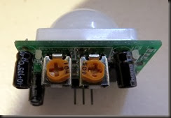
The following table helps to identify the purpose of the potentiometers on the PIR sensor. Most people say they use trial and error. I will attempt to reduce the mystery of these components on the PIR board.
104 (Right) – Min
When you move the 104 labelled potentiometer all the way to the right (min position), the LED will remain on for 1 second after movement is detected. When the LED turns off, it will remain off for 3 seconds before the sensor will trigger again from any further movement. |
105 (Left) – Max
The 105 labelled potentiometer controls the sensitivity of the PIR sensor. When in the left position, the PIR sensor is most sensitive and small amounts of movement will trigger the sensor. It detected my movement (ie a single step to the left of right) from over 10 steps away from the sensor. I was very impressed. |
105 (Right) – Min
When the 105 labelled potentiometer is twisted to the right, the PIR sensor becomes a lot less sensitive. I needed to take much bigger steps to the left or right to trigger the sensor (about 3 times the size compared to the left position). It also had a lot more trouble detecting movement occurring further away. It only really started to detect my movement when I was about 4 steps away from it. |
My preferred combination was 104-Right (min) + 105-Left (max), which meant that the sensor would remain on for only a short period of time, and detect any subtle movements in the room. This combination is displayed below:

I have not tested to see how it performs over a very long period with this setting, and whether it would suffer from false positive readings, but that could easily be fixed by turning the 105 labelled potentiometer a bit more to the right.
[original story: ScottC]


