Posts with «project» label

Easy Way Uses Arduino to Translate Subtitles on the Fly

Using the Video Experimenter shield for Arduino, a group in Brazil developed a way to translate live closed captioning to a number of different languages. Called Easy Way Subtitles, the project uses the Video Experimenter Shield to get the closed captioning text from the broadcasted signal and turns it over [...]

Read the full article on MAKE

Bluetooth Tutorial 1


Introduction:
The bluetooth shield used in this project is a great way to detach the Arduino from your computer. What is even better, is that the shield allows you to control your arduino from your mobile phone or other bluetooth enabled device through simple Serial commands. In this tutorial we will connect a Grove Chainable RGB LED to the bluetooth shield directly, and send simple commands using the Bluetooth SPP app on a Samsung Galaxy S2 to change the colour of the LED (Red , Green and Blue)


Parts Required:
Freetronics Eleven or any compatible Arduino.
Bluetooth shield
Grove Chainable RGB LED
Grove Wire connectors


The Video:


The Arduino Sketch:


Arduino Code:
You can download the Arduino IDE from this site.


 1
2
3
4
5
6
7
8
9
10
11
12
13
14
15
16
17
18
19
20
21
22
23
24
25
26
27
28
29
30
31
32
33
34
35
36
37
38
39
40
41
42
43
44
45
46
47
48
49
50
51
52
53
54
55
56
57
58
59
60
61
62
63
64
65
66
67
68
69
70
71
72
73
74
75
76
77
78
79
80
81
82
83
84
85
86
87
88
89
90
91
92
93
94
95
96
97
98
99
100
101
102
103
104
105
106
107
108
109
110
111
112
113
114
115
116
117
118
119
120
121
122
123
124
125
126
127
128
129
130
131
132
133
134
135
136
137
138
139
140
141
142
143
144
145
146
147
148
149
150
151
152
153
154
155
156
157
158
159
/* This project combines the code from a few different sources.
This project was put together by ScottC on the 15/01/2013
http://arduinobasics.blogspot.com/

Bluetooth slave code by Steve Chang - downloaded from :
http://www.seeedstudio.com/wiki/index.php?title=Bluetooth_Shield

Grove Chainable RGB code can be found here :
http://www.seeedstudio.com/wiki/Grove_-_Chainable_RGB_LED#Introduction

*/

#include <SoftwareSerial.h> //Software Serial Port

#define uint8 unsigned char
#define uint16 unsigned int
#define uint32 unsigned long int

#define RxD 6 // This is the pin that the Bluetooth (BT_TX) will transmit to the Arduino (RxD)
#define TxD 7 // This is the pin that the Bluetooth (BT_RX) will receive from the Arduino (TxD)

#define DEBUG_ENABLED 1


int Clkpin = 9; //RGB LED Clock Pin (Digital 9)
int Datapin = 8; //RGB LED Data Pin (Digital 8)

SoftwareSerial blueToothSerial(RxD,TxD);

/*----------------------SETUP----------------------------*/
void setup() {
Serial.begin(9600); // Allow Serial communication via USB cable to computer (if required)
pinMode(RxD, INPUT); // Setup the Arduino to receive INPUT from the bluetooth shield on Digital Pin 6
pinMode(TxD, OUTPUT); // Setup the Arduino to send data (OUTPUT) to the bluetooth shield on Digital Pin 7
pinMode(13,OUTPUT); // Use onboard LED if required.
setupBlueToothConnection(); //Used to initialise the Bluetooth shield

pinMode(Datapin, OUTPUT); // Setup the RGB LED Data Pin
pinMode(Clkpin, OUTPUT); // Setup the RGB LED Clock pin

}

/*----------------------LOOP----------------------------*/
void loop() {
digitalWrite(13,LOW); //Turn off the onboard Arduino LED
char recvChar;
while(1){
if(blueToothSerial.available()){//check if there's any data sent from the remote bluetooth shield
recvChar = blueToothSerial.read();
Serial.print(recvChar); // Print the character received to the Serial Monitor (if required)

//If the character received = 'r' , then change the RGB led to display a RED colour
if(recvChar=='r'){
Send32Zero(); // begin
DataDealWithAndSend(255, 0, 0); // first node data
Send32Zero(); // send to update data
}

//If the character received = 'g' , then change the RGB led to display a GREEN colour
if(recvChar=='g'){
Send32Zero(); // begin
DataDealWithAndSend(0, 255, 0); // first node data
Send32Zero(); // send to update data
}

//If the character received = 'b' , then change the RGB led to display a BLUE colour
if(recvChar=='b'){
Send32Zero(); // begin
DataDealWithAndSend(0, 0, 255); // first node data
Send32Zero(); // send to update data
}
}

//You can use the following code to deal with any information coming from the Computer (serial monitor)
if(Serial.available()){
recvChar = Serial.read();

//This will send value obtained (recvChar) to the phone. The value will be displayed on the phone.
blueToothSerial.print(recvChar);
}
}
}


//The following code is necessary to setup the bluetooth shield ------copy and paste----------------
void setupBlueToothConnection()
{
blueToothSerial.begin(38400); //Set BluetoothBee BaudRate to default baud rate 38400
blueToothSerial.print("\r\n+STWMOD=0\r\n"); //set the bluetooth work in slave mode
blueToothSerial.print("\r\n+STNA=SeeedBTSlave\r\n"); //set the bluetooth name as "SeeedBTSlave"
blueToothSerial.print("\r\n+STOAUT=1\r\n"); // Permit Paired device to connect me
blueToothSerial.print("\r\n+STAUTO=0\r\n"); // Auto-connection should be forbidden here
delay(2000); // This delay is required.
blueToothSerial.print("\r\n+INQ=1\r\n"); //make the slave bluetooth inquirable
Serial.println("The slave bluetooth is inquirable!");
delay(2000); // This delay is required.
blueToothSerial.flush();
}


//The following code snippets are used update the colour of the RGB LED-----copy and paste------------
void ClkProduce(void){
digitalWrite(Clkpin, LOW);
delayMicroseconds(20);
digitalWrite(Clkpin, HIGH);
delayMicroseconds(20);
}

void Send32Zero(void){
unsigned char i;
for (i=0; i<32; i++){
digitalWrite(Datapin, LOW);
ClkProduce();
}
}

uint8 TakeAntiCode(uint8 dat){
uint8 tmp = 0;
if ((dat & 0x80) == 0){
tmp |= 0x02;
}

if ((dat & 0x40) == 0){
tmp |= 0x01;
}

return tmp;
}

// gray data
void DatSend(uint32 dx){
uint8 i;
for (i=0; i<32; i++){
if ((dx & 0x80000000) != 0){
digitalWrite(Datapin, HIGH);
} else {
digitalWrite(Datapin, LOW);
}

dx <<= 1;
ClkProduce();
}
}

// data processing
void DataDealWithAndSend(uint8 r, uint8 g, uint8 b){
uint32 dx = 0;

dx |= (uint32)0x03 << 30; // highest two bits 1,flag bits
dx |= (uint32)TakeAntiCode(b) << 28;
dx |= (uint32)TakeAntiCode(g) << 26;
dx |= (uint32)TakeAntiCode(r) << 24;

dx |= (uint32)b << 16;
dx |= (uint32)g << 8;
dx |= r;

DatSend(dx);
}

The code above was formatted using hilite.me

Notes:
You don't need to download a library to get this project running. But if you plan to use bluetooth shields to get 2 Arduinos to communicate to each other, then I would advise that you download the library files (which are just examples) from the Seeedstudio site : here.

Visit this site to setup your phone or laptop for bluetooth communication to the shield - here

The app used on my Samsung Galaxy S2 phone was "Bluetooth SPP"

You will initially need to enter a pin of '0000' to establish a connection to the Bluetooth shield - which will appear as "SeeedBTSlave" or whatever text you place on line 90 of the Arduino code above.


Warning !

Not all phones are compatible with the bluetooth shield.
If you have used this shield before - please let me know what phone you used - so that we can build a list and inform others whether their phone is likely to work with this project or not. Obviously - those phones that do not have bluetooth within - will not work :).
And I have not tried any other apps either

I got it to work very easily with my Samsung Galaxy S2 using the free Bluetooth SPP app from the google play store.

This was fun, but I want to make my own app !
Have a look at my latest 4-part tutorial which takes you step-by-step through the process of building your own app using the Processing/Android IDE.
You can build your own GUI interface on your Android Phone and get it to communicate via Bluetooth to your Arduino/Bluetooth Shield. Click on the links below for more information:


If you like this page, please do me a favour and show your appreciation :

 
Visit my ArduinoBasics Google + page.
Follow me on Twitter by looking for ScottC @ArduinoBasics.
Have a look at my videos on my YouTube channel.


However, if you do not have a google profile...
Feel free to share this page with your friends in any way you see fit.

Sonar Project Tutorial


Introduction:
This project utilises the HC-SR04 ultrasonic sensor to scan for nearby objects. You can program the Arduino to sound an alarm when the sensor detects an object within a specific vicinity. Connecting it to a computer allows data to be plotted to make a simple sonar scanner. The scanning ability is made possible through the use of a hobby servo motor SG-5010, and an Adafruit motor shield v1.0.
This project could easily be extended to provide object avoidance for any robotics project. This tutorial was designed so that you could see how the components interact, and also to see how you can use and expand the functionality of the motor shield.


Parts Required:
Freetronics Eleven or any compatible Arduino.
Adafruit motor shield v1.0
HC-SR04 Ultrasonic Sensor
MG-995  or SG-5010 Standard servo
Mini Breadboard 4.5cm x 3.5cm
Female header pins to allow easy access to the analog pins on the Motor Shield
Piezo buzzer - to sound alarm
9V Battery and Battery Clip
Wiresto connect it all together

Gauge parts:

Paper (to print the face of the gauge), and some glue to stick it to the wood.
MDF Standard panel (3mm width) - for the top and base of the gauge, and the pointer.
Galvanized bracket (25x25x40mm)
Timber screws: Hinge-long threads csk head Phillips drive (4G x 12mm)
Velcro dots - to allow temporary application of the mini-breadboard to the gauge.

The gauge was used as a customisable housing for the Arduino and related parts, and to provide some visual feedback of the servo position.


The Video:


The Arduino Sketch:


 Part of the sketch above was created using Fritzing.

The Servo motor can be connected to either of the Servo motor pins (Digital 9 or 10). In this case, the Servo is attached to digital pin 10.Make sure you read the servo motor data sheet and identify the VCC (5V), GND, and Signal connectors. Not all servos have the same colour wires. My servo motor has a white signal wire, a red VCC wire and a black GND wire.

Also when connecting your wires to the HC-SR04, pay attention to the front of the sensor. It will identify the pins for you. Make sure you have the sensor facing the correct way. In this sketch, the sensor is actually facing towards you.

In this sketch - we connect the
    Echo pin to Analog pin 0 (A0).
    Trigger pin to Analog pin 1 (A1)
    VCC to a 5V line/pin 
    and GND to a GND line/pin

Pay attention to your motor shield, I have seen some pictures on the internet where the 5V and GND are reversed.


Arduino Code:
You can download the Arduino IDE from this site.

The motor shield requires the Adafruit motor shield driver library to be installed into the Arduino IDE.

 1
2
3
4
5
6
7
8
9
10
11
12
13
14
15
16
17
18
19
20
21
22
23
24
25
26
27
28
29
30
31
32
33
34
35
36
37
38
39
40
41
42
43
44
45
46
47
48
49
50
51
52
53
54
55
56
57
58
59
60
61
62
63
64
65
66
67
68
69
70
71
72
73
74
75
76
77
78
79
80
81
82
83
84
85
86
87
88
89
90
91
92
93
94
95
96
97
98
99
100
101
102
103
104
/* ArduinoBasics: Sonar Project - Created by Scott C on 10 Jan 2013
http://arduinobasics.blogspot.com/2013/01/arduino-basics-sonar-project-tutorial.html

This project uses the Adafruit Motor shield library (copyright Adafruit Industries LLC, 2009
this code is public domain, enjoy!)

The HC-SR04 sensor uses some code from the following sources:
From Virtualmix: http://goo.gl/kJ8Gl
Modified by Winkle ink here: http://winkleink.blogspot.com.au/2012/05/arduino-hc-sr04-ultrasonic-distance.html
And modified further by ScottC here: http://arduinobasics.blogspot.com/
on 10 Nov 2012.
*/

#include <AFMotor.h>
#include <Servo.h>

// DC hobby servo
Servo servo1;

/* The servo minimum and maximum angle rotation */
static const int minAngle = 0;
static const int maxAngle = 176;
int servoAngle;
int servoPos;
int servoPin = 10;


/* Define pins for HC-SR04 ultrasonic sensor */
#define echoPin A0 // Echo Pin = Analog Pin 0
#define trigPin A1 // Trigger Pin = Analog Pin 1
#define LEDPin 13 // Onboard LED
long duration; // Duration used to calculate distance
long HR_dist=0; // Calculated Distance
int HR_angle=0; // The angle in which the servo/sensor is pointing
int HR_dir=1; // Used to change the direction of the servo/sensor
int minimumRange=5; //Minimum Sonar range
int maximumRange=200; //Maximum Sonar Range

/*--------------------SETUP()------------------------*/
void setup() {
//Begin Serial communication using a 9600 baud rate
Serial.begin (9600);

// Tell the arduino that the servo is attached to Digital pin 10.
servo1.attach(servoPin);

//Setup the trigger and Echo pins of the HC-SR04 sensor
pinMode(trigPin, OUTPUT);
pinMode(echoPin, INPUT);
pinMode(LEDPin, OUTPUT); // Use LED indicator (if required)
}

/*----------------------LOOP()--------------------------*/
void loop() {

/* check if data has been sent from the computer: */
if (Serial.available()) {

/* This expects an integer from the Serial buffer */
HR_angle = Serial.parseInt();

/* If the angle provided is 0 or greater, then move servo to that
position/angle and then get a reading from the ultrasonic sensor */
if(HR_angle>-1){
/*Make sure that the angle provided does not go beyond the capabilities
of the Servo. This can also be used to calibrate the servo angle */
servoPos = constrain(map(HR_angle, 0,180,minAngle,maxAngle),minAngle,maxAngle);
servo1.write(servoPos);

/* Call the getDistance function to take a reading from the Ultrasonic sensor */
getDistance();
}
}
}

/*--------------------getDistance() FUNCTION ---------------*/
void getDistance(){

/* The following trigPin/echoPin cycle is used to determine the
distance of the nearest object by bouncing soundwaves off of it. */
digitalWrite(trigPin, LOW);
delayMicroseconds(2);

digitalWrite(trigPin, HIGH);
delayMicroseconds(10);

digitalWrite(trigPin, LOW);
duration = pulseIn(echoPin, HIGH);

//Calculate the distance (in cm) based on the speed of sound.
HR_dist = duration/58.2;

/*Send the reading from the ultrasonic sensor to the computer */
if (HR_dist >= maximumRange || HR_dist <= minimumRange){
/* Send a 0 to computer and Turn LED ON to indicate "out of range" */
Serial.println("0");
digitalWrite(LEDPin, HIGH);
} else {
/* Send the distance to the computer using Serial protocol, and
turn LED OFF to indicate successful reading. */
Serial.println(HR_dist);
digitalWrite(LEDPin, LOW);
}
}

The code above was formatted using hilite.me

Notes:
Servo Angles: You will notice on line 22, the maximum servo angle used was 176. This value was obtained through trial and error (see below).

Calibrating the servo angles
You may need to calibrate your servo in order to move through an angle of 0 to 180 degrees without straining the motor. Go to line 21-22 and change the minAngle to 0 and the maxAngle to 180. Once you load the sketch to the Arduino/Freetronics ELEVEN, you can then open the Serial Monitor and type a value like 10 <enter>, and then keep reducing it until you get to 0. If you hear the servo motor straining, then move it back up to a safe value and change the minimum servo angle to that value. Do the same for the maximum value.

In this example, the servo's minAngle value was 0, and maxAngle value was 176 after calibration, however, as you can see from the video, the physical range of the servo turned out to be 0 to 180 degrees.


The Processing Sketch

You can download the Processing IDE from this site.

 1
2
3
4
5
6
7
8
9
10
11
12
13
14
15
16
17
18
19
20
21
22
23
24
25
26
27
28
29
30
31
32
33
34
35
36
37
38
39
40
41
42
43
44
45
46
47
48
49
50
51
52
53
54
55
56
57
58
59
60
61
62
63
64
65
66
67
68
69
70
71
72
73
74
75
76
77
78
79
80
81
82
83
84
85
86
87
88
89
90
91
92
93
94
95
96
97
98
99
100
101
102
103
104
105
106
107
108
109
110
/* Created by ScottC on 10 Jan 2013 
http://arduinobasics.blogspot.com/2013/01/arduino-basics-sonar-project-tutorial.html
*/

import processing.serial.*;

int distance;
int angle=0;
int direction=1;

int[] alphaVal = new int[100]; // used to fade the lines
int[] distance2 = new int[100]; // used to store the line lengths
int lineSize = 4; // line length multiplier (makes it longer)

String comPortString;
Serial comPort;

/*---------------------SETUP---------------------------*/
void setup( ) {
size(displayWidth,displayHeight); //allows fullscreen view
smooth();
background(0); // set the background to black

/*Open the serial port for communication with the Arduino
Make sure the COM port is correct - I am using COM port 8 */
comPort = new Serial(this, "COM8", 9600);
comPort.bufferUntil('\n'); // Trigger a SerialEvent on new line

/*Initialise the line alphaValues to 0 (ie not visible) */
for(int i=0; i<91; i++){
alphaVal[i] = 0;
}
}

/*---------------------DRAW-----------------*/
void draw( ) {
background(0); //clear the screen

/*Draw each line and dot */
for(int i=0; i<91; i++){

/*Gradually fade each line */
alphaVal[i]=alphaVal[i]-4;

/*Once it gets to 0, keep it there */
if(alphaVal[i]<0){
alphaVal[i]=0;
}

/*The colour of the line will change depending on the distance */
stroke(255,distance2[i],0,alphaVal[i]);

/* Use a line thickness of 2 (strokeweight) to draw the line that fans
out from the bottom center of the screen. */
strokeWeight(2);
line(width/2, height, (width/2)-cos(radians(i*2))*(distance2[i]*lineSize), height-sin(radians(i*2))*(distance2[i]*lineSize));

/* Draw the white dot at the end of the line which does not fade */
stroke(255);
strokeWeight(1);
ellipse((width/2)-cos(radians(i*2))*(distance2[i]*lineSize), height-sin(radians(i*2))*(distance2[i]*lineSize),5,5);
}
}

/* A mouse press starts the scan. There is no stop button */
void mousePressed(){
sendAngle();
}

/*When the computer receives a value from the Arduino, it will update the line positions */
void serialEvent(Serial cPort){
comPortString = cPort.readStringUntil('\n');
if(comPortString != null) {
comPortString=trim(comPortString);

/* Use the distance received by the Arduino to modify the lines */
distance = int(map(Integer.parseInt(comPortString),1,200,1,height));
drawSonar(angle,distance);

/* Send the next angle to be measured by the Arduino */
sendAngle();
}
}

/*---------------------------sendAngle() FUNCTION----------------*/
void sendAngle(){
//Send the angle to the Arduino. The fullstop at the end is necessary.
comPort.write(angle+".");

/*Increment the angle for the next time round. Making sure that the angle sent
does not exceed the servo limits. The "direction" variable allows the servo
to have a sweeping action.*/
angle=angle+(2*direction);
if(angle>178||angle<1){
direction=direction*-1;
}
}

/*-----------------sketchFullScreen(): Allows for FullScreen view------*/
boolean sketchFullScreen() {
return true;
}

/*----------------- drawSonar(): update the line/dot positions---------*/
void drawSonar(int sonAngle, int newDist){
alphaVal[sonAngle/2] = 180;
distance2[sonAngle/2] = newDist;
}


The Processing Output


iPacemaker with Arduino

When we say “there are no limit for  Arduino”, here we have a project,  sent by [ladvine] in wich Arduino meets biomedic tech. The WiFi shield is the real application when they speak about Arduino. There is a long paper about it on this [website] that I suggest to visit to understand more this important project.

iPacemaker is an reprogrammable implant pacemaker with wireless connectivity.
A user friendly embedded web interface helps in changing every parameters of the implantable pacemaker. The important feature is the WiFi alliance complaint hardware which supports every wireless device to establish connection with the IMD. GSM connectivity can be used in absence of WiFi in remote areas helping in Telemetry.
Wireless protection in case of WiFi is enabled through WPA2 security with AES Encryption and Java Web interface which has inherent security capabilities. Shielding the GSM and WiFi antennas helps reduce unwanted patient radiations.

Arduino Blog 14 Dec 17:21

Analog IR Temperature gauge


Introduction:
The IRTEMP module from Freetronics is an infrared remote temperature sensor that can be incorporated into your Arduino / microcontroller projects. It can scan a temperature between -33 to +220 C, and can be operated using a 3.3 to 5V power supply. It can be powered directly from the Arduino 5V pin.  This module can also provide an ambient temperature reading if required.
The Servo used in this project is a SG-5010 standard servo which will be utilised to display the temperature reading from the IRTEMP module.


Parts Required:
Freetronics Eleven or any compatible Arduino.
Freetronics IRTEMP module
MG-995  or SG-5010 Standard servo
Mini Breadboard 4.5cm x 3.5cm
Protoshieldand female header pins (not essential - but makes it more tidy)
9V Battery and Battery Clip
Wiresto connect it all together

Gauge parts:
Paper (to print the face of the gauge), and some glue to stick it to the wood.
MDF Standard panel (3mm width) - for the top and base of the gauge.
Galvanized bracket (25x25x40mm)
Timber screws: Hinge-long threads csk head Phillips drive (4G x 12mm)


The Video:


The Arduino Sketch:


     The above sketch was created using Fritzing.


Arduino Code:
You can download the Arduino IDE from this site.

The IRTemp gauge requires a driver library to be installed into the Arduino IDE.
The latest IRTemp driver library can be found here.

 1
2
3
4
5
6
7
8
9
10
11
12
13
14
15
16
17
18
19
20
21
22
23
24
25
26
27
28
29
30
31
32
33
34
35
36
37
38
39
40
41
42
43
44
45
46
47
48
49
50
51
52
53
54
55
56
57
58
59
60
61
62
63
64
65
66
67
68
69
70
71
72
73
74
75
76
77
78
79
80
81
82
83
84
/* -------------------------------------------------------
Analog IR Temperature Gauge: written by ScottC on 1st Dec 2012.
http://arduinobasics.blogspot.com/2012/12/arduino-basics-analog-ir-temperature.html


* Some of the code was adapted from a sketch by Andy Gelme (@geekscape)
* For more information on using the IRTEMP
see www.freetronics.com/irtemp

* IRTemp library uses an Arduino interrupt:
* If PIN_CLOCK = 2, then Arduino interrupt 0 is used
* If PIN_CLOCK = 3, then Arduino interrupt 1 is used
---------------------------------------------------------*/

#include "IRTemp.h"
#include <Servo.h>

Servo servo1;
static const byte PIN_DATA = 2;
static const byte PIN_CLOCK = 3; // Must be either pin 2 or pin 3
static const byte PIN_ACQUIRE = 4;

static const bool SCALE=false; // Celcius: false, Farenheit: true

/* Used to capture the temperature from the IRTEMP sensor */
float irTemperature;
int temp;

/* The minimum and maximum temperatures on the gauge. */
static const int minTemp = -45;
static const int maxTemp = 135;


/* The servo minimum and maximum angle rotation */
static const int minAngle = 0;
static const int maxAngle = 175;
int servoPos;

IRTemp irTemp(PIN_ACQUIRE, PIN_CLOCK, PIN_DATA);


/*----------------------SETUP----------------------*/

void setup(void) {

servo1.attach(9); // turn on servo
}


/*-----------------------LOOP-----------------------*/

void loop(void) {
irTemperature = irTemp.getIRTemperature(SCALE);
printTemperature("IR", irTemperature);

/* If you want the ambient temperature instead - then use the code below. */
//float ambientTemperature = irTemp.getAmbientTemperature(SCALE);
//printTemperature("Ambient", ambientTemperature);

}

/*-----------printTemperature function---------------*/

void printTemperature(char *type, float temperature) {

temp=(int) temperature;
servoPos = constrain(map(temp, minTemp,maxTemp,minAngle,maxAngle),minAngle,maxAngle);

if (isnan(temperature)) {
//is not a number, do nothing
}
else {

/* To test the minimum angle insert the code below */
//servoPos = minAngle;

/*To test the maximum angle, insert the code below */
//servoPos = maxAngle;

/* Rotate servo to the designated position */
servo1.write(servoPos);
}
}

The code above was formatted using hilite.me

Notes:
Ambient temperature: If you want to get the ambient temperature from the IRTEMP module, then have a look at lines 58-59.
Servo Angles: You will notice on line 36, the maximum servo angle used was 175. This value was obtained through trial and error (see below).

Calibrating the servo angles
You may need to calibrate your servo in order to move through an angle of 0 to 180 degrees without straining the motor.Change the minAngle on line 35to a safe value (for example: 10), and the maxAngle on line 36 to a value like 170. Remove the comment tag (//) on line 76, and then run the sketch. Lower the minAngle until it reaches the minimum value on the gauge, making sure that the servo doesn't sound like it is straining to keep it in position.

Add the comment tag (//) back in, and then take out the comment tag for line 79. And follow a similar process, until you reach the maximum value on the gauge. Once again, make sure that the servo is not making a straining noise to hold it at that value. Make sure to add the comment tag back in, when you have finished the calibration.

In this example, the servo's minAngle value was 0, and maxAngle value was 175 after calibration, however, as you can see from the video, the physical range of the servo turned out to be 0 to 180 degrees.


The Temperature Gauge Picture

The following gauge was created in Microsoft Excel using an X-Y chart.  Data labels were manually repositioned in order to get the desired numerical effect.


HC-SR04 Ultrasonic Sensor


Introduction:

The HC-SR04 Ultrasonic Sensor is a very affordable proximity/distance sensor that has been used mainly for object avoidance in various robotics projects . It essentially gives your Arduino eyes / spacial awareness and can prevent your robot from crashing or falling off a table. It has also been used in turret applications, water level sensing, and even as a parking sensor. This simple project will use the HC-SR04 sensor with an Arduino and a Processing sketch to provide a neat little interactive display on your computer screen.


Parts Required:
Freetronics Eleven or any compatible Arduino.
HC-SR04 Ultrasonic Sensor
Mini Breadboard 4.5cm x 3.5cm
Protoshieldand female header pins (not essential - but makes it more tidy)
Wiresto connect it all together


The Video:


The Arduino Sketch:


     The above sketch was created using Fritzing.


Arduino Code:
You can download the Arduino IDE from this site.

 1
2
3
4
5
6
7
8
9
10
11
12
13
14
15
16
17
18
19
20
21
22
23
24
25
26
27
28
29
30
31
32
33
34
35
36
37
38
39
40
41
42
43
44
45
46
47
48
49
50
51
52
53
54
55
56
57
58
59
60
/*
HC-SR04 Ping distance sensor:
VCC to arduino 5v
GND to arduino GND
Echo to Arduino pin 7
Trig to Arduino pin 8

This sketch originates from Virtualmix: http://goo.gl/kJ8Gl
Has been modified by Winkle ink here: http://winkleink.blogspot.com.au/2012/05/arduino-hc-sr04-ultrasonic-distance.html
And modified further by ScottC here: http://arduinobasics.blogspot.com.au/2012/11/arduinobasics-hc-sr04-ultrasonic-sensor.html
on 10 Nov 2012.
*/


#define echoPin 7 // Echo Pin
#define trigPin 8 // Trigger Pin
#define LEDPin 13 // Onboard LED

int maximumRange = 200; // Maximum range needed
int minimumRange = 0; // Minimum range needed
long duration, distance; // Duration used to calculate distance

void setup() {
Serial.begin (9600);
pinMode(trigPin, OUTPUT);
pinMode(echoPin, INPUT);
pinMode(LEDPin, OUTPUT); // Use LED indicator (if required)
}

void loop() {
/* The following trigPin/echoPin cycle is used to determine the
distance of the nearest object by bouncing soundwaves off of it. */
digitalWrite(trigPin, LOW);
delayMicroseconds(2);

digitalWrite(trigPin, HIGH);
delayMicroseconds(10);

digitalWrite(trigPin, LOW);
duration = pulseIn(echoPin, HIGH);

//Calculate the distance (in cm) based on the speed of sound.
distance = duration/58.2;

if (distance >= maximumRange || distance <= minimumRange){
/* Send a negative number to computer and Turn LED ON
to indicate "out of range" */
Serial.println("-1");
digitalWrite(LEDPin, HIGH);
}
else {
/* Send the distance to the computer using Serial protocol, and
turn LED OFF to indicate successful reading. */
Serial.println(distance);
digitalWrite(LEDPin, LOW);
}

//Delay 50ms before next reading.
delay(50);
}

The code above was formatted using hilite.me


Processing Code:
You can download the Processing IDE from this site.

 1
2
3
4
5
6
7
8
9
10
11
12
13
14
15
16
17
18
19
20
21
22
23
24
25
26
27
28
29
30
31
32
33
34
35
36
37
38
39
40
41
42
43
44
45
46
47
48
49
50
51
52
53
54
55
56
57
58
59
60
61
62
63
64
65
66
67
68
69
70
71
72
73
74
75
76
77
78
79
80
81
82
83
84
85
86
87
88
89
90
91
92
93
94
95
96
97
98
99
100
101
102
103
104
105
106
107
108
109
110
111
112
113
114
115
116
117
118
119
120
121
122
123
124
125
126
127
128
/* The following Processing Sketch was created by ScottC on
the 10 Nov 2012 : http://arduinobasics.blogspot.com/

Inspired by this Processing sketch by Daniel Shiffman:
http://processing.org/learning/basics/sinewave.html

*/
import processing.serial.*;


int numOfShapes = 60; // Number of squares to display on screen
int shapeSpeed = 2; // Speed at which the shapes move to new position
// 2 = Fastest, Larger numbers are slower

//Global Variables
Square[] mySquares = new Square[numOfShapes];
int shapeSize, distance;
String comPortString;
Serial myPort;

/* -----------------------Setup ---------------------------*/
void setup(){
size(displayWidth,displayHeight); //Use entire screen size.
smooth(); // draws all shapes with smooth edges.

/* Calculate the size of the squares and initialise the Squares array */
shapeSize = (width/numOfShapes);
for(int i = 0; i<numOfShapes; i++){
mySquares[i]=new Square(int(shapeSize*i),height-40);
}

/*Open the serial port for communication with the Arduino
Make sure the COM port is correct - I am using COM port 8 */
myPort = new Serial(this, "COM8", 9600);
myPort.bufferUntil('\n'); // Trigger a SerialEvent on new line
}

/* ------------------------Draw -----------------------------*/
void draw(){
background(0); //Make the background BLACK
delay(50); //Delay used to refresh screen
drawSquares(); //Draw the pattern of squares
}


/* ---------------------serialEvent ---------------------------*/
void serialEvent(Serial cPort){
comPortString = cPort.readStringUntil('\n');
if(comPortString != null) {
comPortString=trim(comPortString);

/* Use the distance received by the Arduino to modify the y position
of the first square (others will follow). Should match the
code settings on the Arduino. In this case 200 is the maximum
distance expected. The distance is then mapped to a value
between 1 and the height of your screen */
distance = int(map(Integer.parseInt(comPortString),1,200,1,height));
if(distance<0){
/*If computer receives a negative number (-1), then the
sensor is reporting an "out of range" error. Convert all
of these to a distance of 0. */
distance = 0;
}
}
}


/* ---------------------drawSquares ---------------------------*/
void drawSquares(){
int oldY, newY, targetY, redVal, blueVal;

/* Set the Y position of the 1st square based on
sensor value received */
mySquares[0].setY((height-shapeSize)-distance);

/* Update the position and colour of each of the squares */
for(int i = numOfShapes-1; i>0; i--){
/* Use the previous square's position as a target */
targetY=mySquares[i-1].getY();
oldY=mySquares[i].getY();

if(abs(oldY-targetY)<2){
newY=targetY; //This helps to line them up
}else{
//calculate the new position of the square
newY=oldY-((oldY-targetY)/shapeSpeed);
}
//Set the new position of the square
mySquares[i].setY(newY);

/*Calculate the colour of the square based on its
position on the screen */
blueVal = int(map(newY,0,height,0,255));
redVal = 255-blueVal;
fill(redVal,0,blueVal);

/* Draw the square on the screen */
rect(mySquares[i].getX(), mySquares[i].getY(),shapeSize,shapeSize);
}
}

/* ---------------------sketchFullScreen---------------------------*/
// This puts processing into Full Screen Mode
boolean sketchFullScreen() {
return true;
}

/* ---------------------CLASS: Square ---------------------------*/
class Square{
int xPosition, yPosition;

Square(int xPos, int yPos){
xPosition = xPos;
yPosition = yPos;
}

int getX(){
return xPosition;
}

int getY(){
return yPosition;
}

void setY(int yPos){
yPosition = yPos;
}
}

The code above was formatted using hilite.me


If you like this page, please do me a favour and show your appreciation :

  Visit my ArduinoBasics Google + page.
Follow me on Twitter by looking for ScottC @ArduinoBasics.
Have a look at my videos on my YouTube channel.


However, if you do not have a google profile...
Feel free to share this page with your friends in any way you see fit.

Babel Fish Language Toy


Fans of Douglas Adams will no doubt catch the reference to The Hitchhiker’s Guide to the Galaxy in the title of Becky Stern’s latest project, The Babel Fish Language Toy. This sound- and RFID-enabled Arduino project with a crafty enclosure helps you learn foreign languages with RFID flash cards. When you bring a flash card near the fish’s tongue, you’ll hear the pronunciation of the word, which comes from .WAV files that you pre-load onto the SD card. And naturally, a full how-to writeup and video will help you along the way should you decide to make your own. Xie xie Becky!


Filed under: Arduino, Education
MAKE » Arduino 04 Aug 14:00
arduino  education  fish  language  nfc  project  rfid  toy  

Grove OLED 96x96 Slideshow

This project makes use of the Grove OLED 96x96 display to present a mini-slideshow.  Pictures on your computer are transferred to the OLED via a Processing script, and will cycle through them as many times as you choose.

Video:


Parts required:


Software required:


Sketch:


Arduino Sketch:
 1
2
3
4
5
6
7
8
9
10
11
12
13
14
15
16
17
18
19
20
21
22
23
24
25
26
27
28
29
30
31
32
33
34
35
36
37
38
39
40
41
42
43
44
45
46
47
48
49
50
51
52
53
54
55
56
57
58
59
60
61
62
63
// OLED Slideshow: Arduino Sketch written by ScottC 21/07/2012

#include <Wire.h>
#include <SeeedGrayOLED.h> //From http://garden.seeedstudio.com/images/c/c4/SeeedGrayOLED.zip
#include <avr/pgmspace.h>

int counter=0;

void setup()
{
//Allow communication to OLED
Wire.begin();

//Allow Serial communication between Freetronics Eleven and Computer
Serial.begin(28800);

//Initialise the OLED
SeeedGrayOled.init();
//Clear the OLED display
SeeedGrayOled.clearDisplay();
//Set to vertical mode - horizontal mode doesn't work with this example
SeeedGrayOled.setVerticalMode();

}

void loop(){
//Listen for Serial comunication
while (Serial.available()>0) {
// Read data and send directly to the OLED
sendMyData(Serial.read());
counter++;

//When counter reaches 4608 pixels, the picture is complete.
if(counter>4607){
//Insert delay to allow viewing of picture.
delay(4000);
Serial.println("End of Transmission");

//Reset the counter for the next picture
counter=0;
}
}
}

// This function was adapted from the SEEED Gray OLED driver so that
// character bytes could be sent directly to the OLED.
void sendMyData(unsigned char Data){
Wire.beginTransmission(SeeedGrayOLED_Address); // begin I2C transmission
Wire.send(SeeedGrayOLED_Data_Mode); // data mode
Wire.send(Data);
Wire.endTransmission();
}


// This function was adapted from the SEEED Gray OLED driver so that
// commands could be sent directly to the OLED.
// NOT USED IN THIS EXAMPLE ***********************
void sendMyCommand(unsigned char Cmd){
Wire.beginTransmission(SeeedGrayOLED_Address); // begin I2C communication
Wire.send(SeeedGrayOLED_Command_Mode); // Set OLED Command mode
Wire.send(Cmd);
Wire.endTransmission(); // End I2C communication
}


Processing Sketch:
  1
2
3
4
5
6
7
8
9
10
11
12
13
14
15
16
17
18
19
20
21
22
23
24
25
26
27
28
29
30
31
32
33
34
35
36
37
38
39
40
41
42
43
44
45
46
47
48
49
50
51
52
53
54
55
56
57
58
59
60
61
62
63
64
65
66
67
68
69
70
71
72
73
74
75
76
77
78
79
80
81
82
83
84
85
86
87
88
89
90
91
92
93
94
95
96
97
98
99
100
101
102
103
104
105
106
107
108
109
110
111
112
113
114
115
116
117
118
119
120
121
122
123
124
125
126
127
128
129
130
/* OLED Slideshow: Processing Sketch Written by ScottC 21/7/2012 

References:
Getting Pixels: http://www.learningprocessing.com/examples/chapter-15/example-15-7/
Greyscale conversion = http://www.openprocessing.org/sketch/60336
*/


import processing.serial.*; /* Needed for Serial Communication */

/* Global variables */
Serial comPort;
String [] comPortList;
String comPortString;
PImage img;
char[] tempGrey=new char[4609];
int startOffset=0;
ArrayList picNames;
int curLoop=1;
int totalPics=0;
int curPicNum=0;
boolean toggleSend=true;
boolean sendBouncer=true;

//Change maxLoops to a number > 1 if you want the pictures to loop.
int maxLoops=1;


void setup() {
//The size of the display is critical (must match the OLED)
size(96, 96);
//setup Serial
comPortList = Serial.list();
if(comPortList.length>0){
//baud rates greater than 28800 may produce unexpected results
comPort = new Serial(this, comPortList[0], 28800);
comPort.bufferUntil('\n');
} else{
println("NO COM PORTS AVAILABLE");
}

//Create an Array of pictures
picNames=new ArrayList();
picNames.add("Picture1.bmp");
picNames.add("Picture2.bmp");
picNames.add("Picture3.bmp");
picNames.add("Picture4.bmp");
// for more pictures just keep adding them to the list.
//The actual pictures must be located in the data folder of this project.
//Select Sketch/Add File to add the files to this folder.
//Make sure that the name of pictures match the names above.

//Get the total number of pictures added
totalPics=picNames.size();
}

void draw(){
if(toggleSend && sendBouncer){

// Debugging code: print("STARTED:");
// Debugging code: println(picNames.get(curPicNum));

sendImage((String)picNames.get(curPicNum)); //Send the picture to the OLED
toggleSend=false; //temporarily stop sending any more pictures until authorised
curPicNum++; //increment in preparation for the next picture

if(curPicNum==totalPics){
curPicNum=0; //go back to the first picture
curLoop++; //increment the loop counter
}
if(curLoop>maxLoops){
sendBouncer=false; //Stop any further looping
println("ANIMATION COMPLETE");
}
}
}


void sendImage(String imgName){
img = loadImage(imgName);
image(img,0,0,width,height);
loadPixels();
int counter=0;
for (int x = 0; x < width; x=x+2) {
for (int y = 0; y < height; y++) {
counter++;
int PixLoc = x + y*height; // this reads down then across2.
//Left pixel nibble
int Pix1=(round((red(pixels[PixLoc])*0.222+green(pixels[PixLoc])*0.707+blue(pixels[PixLoc])*0.071)))/16;
//Right pixel nibble
int Pix2=(round((red(pixels[PixLoc+1])*0.222+green(pixels[PixLoc+1])*0.707+blue(pixels[PixLoc+1])*0.071)))/16;
//Shift the byte <<4 for the left pixel nibble
int PixShift1=Pix1<<4;
//Combine both nibbles to form a byte
int PixFin = PixShift1+Pix2;
byte PixByteFin=byte(PixFin);
//Assign this byte to the tempGrey array
tempGrey[counter] = char(PixByteFin);
}
}
sendSerial(tempGrey); //Send the image data through the Serial COM Port/
}


//This function will send the byte/Char array to the Freetronics
//Eleven or Arduino.
void sendSerial(char[] Data){
for(int i=0; i<4608; i++){
//Needs an offset to get picture to align to screen properly
//only needs to do this once.
if(startOffset==0){
i=i+6;
startOffset++;
}
//Send the picture data to the Freetronics Eleven / Arduino
comPort.write(Data[i]);
}
}


//This function will wait for a response from the Freetronics
//Eleven or Arduino before sending any further pictures.
void serialEvent (Serial myPort) {
// get the ASCII string:
String inString = myPort.readStringUntil('\n');
if (inString != null) {
println(inString);
toggleSend=true; // Allow the next picture to be sent
}
}


Please note: that you must use the Arduino IDE version 023 until Seeed Studio update their driver for this OLED. Their current driver is not compatible with later versions of Arduino IDE.


Mouse Controlling Arduino LEDs


Use a mouse to control LEDs attached to an Arduino. This project uses the processing language to transmit the mouse coordinates to the Arduino, which then uses this information to turn on some LEDs. Please see the video below to see it in action.


Components Required for this project:

  • Arduino UNO
  • Breadboard
  • 9 LEDs
  • 9 x 330 ohm resistors
  • Wires to connect the circuit
  • USB connection cable: to connect the computer to the Arduino
  • A computer: to run the processing sketch, and to compile / upload the Arduino sketch
  • Processing Program installed on computer
  • Arduino Program installed on the computer

Arduino Sketch


This was made using Fritzing.

Arduino Code

You can download the Arduino IDE from this site.

 1
2
3
4
5
6
7
8
9
10
11
12
13
14
15
16
17
18
19
20
21
22
23
24
25
26
27
28
29
30
31
32
33
34
35
36
37
38
39
40
41
42
/* This program was created by ScottC on 9/5/2012 to receive serial 
signals from a computer to turn on/off 1-9 LEDs */

void setup() {
// initialize the digital pins as an output.
pinMode(2, OUTPUT);
pinMode(3, OUTPUT);
pinMode(4, OUTPUT);
pinMode(5, OUTPUT);
pinMode(6, OUTPUT);
pinMode(7, OUTPUT);
pinMode(8, OUTPUT);
pinMode(9, OUTPUT);
pinMode(10, OUTPUT);
// Turn the Serial Protocol ON
Serial.begin(9600);
}

void loop() {
byte byteRead;

/* check if data has been sent from the computer: */
if (Serial.available()) {

/* read the most recent byte */
byteRead = Serial.read();
//You have to subtract '0' from the read Byte to convert from text to a number.
byteRead=byteRead-'0';

//Turn off all LEDS
for(int i=2; i<11; i++){
digitalWrite(i, LOW);
}

if(byteRead>0){
//Turn on the relevant LEDs
for(int i=1; i<(byteRead+1); i++){
digitalWrite(i+1, HIGH);
}
}
}
}

The code above was formatted using this site.


Processing Code

You can download the Processing IDE from this site.

 1
2
3
4
5
6
7
8
9
10
11
12
13
14
15
16
17
18
19
20
21
22
23
24
25
26
27
28
29
30
31
32
33
34
35
36
37
38
39
40
41
42
43
44
45
46
47
48
49
50
51
52
53
54
//Created by ScottC on 12/05/2012 to send mouse coordinates to Arduino

import processing.serial.*;

// Global variables
int new_sX, old_sX;
int nX, nY;
Serial myPort;

// Setup the Processing Canvas
void setup(){
size( 800, 400 );
strokeWeight( 10 );

//Open the serial port for communication with the Arduino
//Make sure the COM port is correct
myPort = new Serial(this, "COM6", 9600);
myPort.bufferUntil('\n');
}

// Draw the Window on the computer screen
void draw(){

// Fill canvas grey
background( 100 );

// Set the stroke colour to white
stroke(255);

// Draw a circle at the mouse location
ellipse( nX, nY, 10, 10 );

//Draw Line from the top of the page to the bottom of the page
//in line with the mouse.
line(nX,0,nX,height);
}


// Get the new mouse location and send it to the arduino
void mouseMoved(){
nX = mouseX;
nY = mouseY;

//map the mouse x coordinates to the LEDs on the Arduino.
new_sX=(int)map(nX,0,800,0,10);

if(new_sX==old_sX){
//do nothing
} else {
//only send values to the Arduino when the new X coordinates are different.
old_sX = new_sX;
myPort.write(""+new_sX);
}
}

The code above was formatted using this site.

Reading from a Text File and Sending to Arduino

The following tutorial will demonstrate how to Read values from a Text file (.txt, .csv) to blink 1 of 9 LEDs attached to an Arduino. It uses the combination of an Arduino and Processing program to process the file. The Processing program will read the text file in real time, only sending new information to the Arduino.


Components Required

  • Arduino UNO
  • Breadboard
  • 9 LEDs
  • 9 x 330 ohm resistors
  • Wires to connect the circuit
  • USB connection cable: to connect the computer to the Arduino
  • A computer: to run the processing sketch, and to compile / upload the Arduino sketch
  • Processing Program installed on computer
  • Arduino Program installed on the computer
  • A comma separated text file (*.txt).


Arduino Layout


The Text File

  • Open Notepad or equivalent text file editor, and paste the following data into it.

1,2,3,4,5,6,7,8,9,8,7,6,5,4,3,2,1

  • Save the file on your hard drive. In my case, I have chosen to save the file at this location.

D:/mySensorData.txt

  • It should look like the following screenshot


Additional notes regarding the Text file:
  • Just remember what you call it, and where you saved it, because we will be referring to this file later on in the Processing script.
  • Keep all values on the same line.
  • Separate each number with a comma.
  • The number 1 will blink the first LED which is attached to Pin 2 on the Arduino.
  • The number 9 will blink the last LED which is attached to Pin 10 on the Arduino.


Processing Code

You can download the Processing IDE from this site.

 1
2
3
4
5
6
7
8
9
10
11
12
13
14
15
16
17
18
19
20
21
22
23
24
25
26
27
28
29
30
31
32
33
34
35
36
37
38
39
40
41
42
43
44
45
46
47
48
49
50
51
52
53
54
55
56
57
58
59
60
61
62
63
64
65
66
67
68
69
70
71
72
73
74
75
76
77
78
79

style="color: blue;">import
processing.serial.*;

style="color: blue;">import
java.io.*;

style="color: rgb(43, 145, 175);">int
mySwitch=0;

style="color: rgb(43, 145, 175);">int
counter=0;
String [] subtext;
Serial myPort;


style="color: rgb(43, 145, 175);">void
setup(){

style="color: green;">//Create a switch that will control the frequency of text file reads.


style="color: green;">//When mySwitch=1, the program is setup to read the text file.


style="color: green;">//This is turned off when mySwitch = 0

mySwitch=1;


style="color: green;">//Open the serial port for communication with the Arduino


style="color: green;">//Make sure the COM port is correct

myPort =
style="color: blue;">new
Serial(this,
style="color: rgb(163, 21, 21);">"COM6"
, 9600);
myPort.bufferUntil(
style="color: rgb(163, 21, 21);">'\n'
);
}


style="color: rgb(43, 145, 175);">void
draw() {

style="color: blue;">if
(mySwitch>0){

style="color: green;">/*The readData function can be found later in the code.


style="color: green;"> This is the call to read a CSV file on the computer hard-drive. */

readData(
style="color: rgb(163, 21, 21);">"D:/mySensorData.txt"
);


style="color: green;">/*The following switch prevents continuous reading of the text file, until


style="color: green;"> we are ready to read the file again. */

mySwitch=0;
}

style="color: green;">/*Only send new data. This IF statement will allow new data to be sent to


style="color: green;"> the arduino. */


style="color: blue;">if
(counter<subtext.length){

style="color: green;">/* Write the next number to the Serial port and send it to the Arduino


style="color: green;"> There will be a delay of half a second before the command is


style="color: green;"> sent to turn the LED off : myPort.write('0'); */

myPort.write(subtext[counter]);
delay(500);
myPort.write(
style="color: rgb(163, 21, 21);">'0'
);
delay(100);

style="color: green;">//Increment the counter so that the next number is sent to the arduino.

counter++;
}
style="color: blue;">else
{
//If the text file has run out of numbers, then read the text file again in 5 seconds.
delay(5000);
mySwitch=1;
}
}


style="color: green;">/* The following function will read from a CSV or TXT file */


style="color: rgb(43, 145, 175);">void
readData(String myFileName){

File file=
style="color: blue;">new
File(myFileName);
BufferedReader br=
style="color: blue;">null
;

try{
br=
style="color: blue;">new
BufferedReader(
style="color: blue;">new
FileReader(file));
String text=
style="color: blue;">null
;


style="color: green;">/* keep reading each line until you get to the end of the file */


style="color: blue;">while
((text=br.readLine())!=
style="color: blue;">null
){
/* Spilt each line up into bits and pieces using a comma as a separator */
subtext = splitTokens(text,
style="color: rgb(163, 21, 21);">","
);
}
}
style="color: blue;">catch
(FileNotFoundException e){
e.printStackTrace();
}
style="color: blue;">catch
(IOException e){
e.printStackTrace();
}
style="color: blue;">finally
{
try {

style="color: blue;">if
(br != null){
br.close();
}
}
style="color: blue;">catch
(IOException e) {
e.printStackTrace();
}
}
}

I used this site to highlight and format my code.

Once you have copied the text above into the Processing IDE, you can now start working on the Arduino code as seen below.


Arduino Code

You can download the Arduino IDE from this site.

Copy and paste the following code into the Arduino IDE.

 1
2
3
4
5
6
7
8
9
10
11
12
13
14
15
16
17
18
19
20
21
22
23
24
25
26
27
28
29
30
31
32
33
34
35
36
37
38
39
40
41
42
43
44
45
46
47
48
49

style="color: green;">/* This program was created by ScottC on 8/5/2012 to receive serial


style="color: green;">signals from a computer to turn on/off 1-9 LEDs */


style="color: rgb(43, 145, 175);">void
setup() {

style="color: green;">// initialize the digital pins as an output.

pinMode(2, OUTPUT);
pinMode(3, OUTPUT);
pinMode(4, OUTPUT);
pinMode(5, OUTPUT);
pinMode(6, OUTPUT);
pinMode(7, OUTPUT);
pinMode(8, OUTPUT);
pinMode(9, OUTPUT);
pinMode(10, OUTPUT);

style="color: green;">// Turn the Serial Protocol ON

Serial.begin(9600);
}


style="color: rgb(43, 145, 175);">void
loop() {

style="color: rgb(43, 145, 175);">byte
byteRead;


style="color: green;">/* check if data has been sent from the computer: */


style="color: blue;">if
(Serial.available()) {


style="color: green;">/* read the most recent byte */

byteRead = Serial.read();

style="color: green;">//You have to subtract '0' from the read Byte to convert from text to a number.

byteRead=byteRead-
style="color: rgb(163, 21, 21);">'0'
;


style="color: green;">//Turn off all LEDs if the byte Read = 0


style="color: blue;">if
(byteRead==0){

style="color: green;">//Turn off all LEDS

digitalWrite(2, LOW);
digitalWrite(3, LOW);
digitalWrite(4, LOW);
digitalWrite(5, LOW);
digitalWrite(6, LOW);
digitalWrite(7, LOW);
digitalWrite(8, LOW);
digitalWrite(9, LOW);
digitalWrite(10, LOW);
}


style="color: green;">//Turn LED ON depending on the byte Read.


style="color: blue;">if
(byteRead>0){
digitalWrite((byteRead+1), HIGH);
style="color: green;">// set the LED on

}
}
}

Additional Information:
  • The Arduino code will still work without the processing program. You can open the serial monitor window to send the commands to the Arduino manually. In fact, if you encounter any problems, I would suggest you do this. It will help to identify the root cause of the problem (ie Processing or Arduino Code, or physical connections).
  • If you choose to use the Serial Monitor feature of the Arduino IDE, you cannot use the Processing program at the same time.

Once you have assembled the Arduino with all the wires, LEDs, resistors etc, you should now be ready to put it all together and get this baby cranking!


Connecting it all together

  • Connect the USB cable from your computer to the Arduino, and upload the code.
  • Keep the USB cable connected between the Arduino and the computer, as this will become the physical connection needed by the Processing Program
  • Make sure that you have the text file in the correct location on your hard drive, and that it only contains numbers relevant to the code provided (separated by commas).
  • Run the Processing program and watch the LEDs blink in the sequence described by the text file.
  • You can add more numbers to the end of the line, however, the processing program will not be aware of them until you save the file. The text file does not have to be closed.
Other programs can be used to create text file, but you will need the processing program to read the file and send the values to the Arduino. The Arduino will receive each value and react appropriately.

SIMILAR PROJECT: Use a mouse to control the LEDs on your Arduino - see this post.


An alternative Processing Sketch

This Processing sketch uses the loadStrings()method instead of the FileReader method used in the first sketch. This sketch also provides better control over sending the values to the Arduino. When the sketch first loads, the application window will be red. By clicking your mouse inside the window, the background will turn green and the file will be imported and sent to the Arduino, with every value being sent at half second intervals. If you update the text file and save, only new values will be transmitted, however, if you want the entire file to transmit again, you can press the window once (to reset the counter), and then again to read the file and send the values again from the beginning of the file.
I personally like this updated version better than the first, plus I was inspired to update this blog posting due to the fact that some people were having problems with the FileReader method in the first sketch. But both sketches should work (they worked for me).


 1
2
3
4
5
6
7
8
9
10
11
12
13
14
15
16
17
18
19
20
21
22
23
24
25
26
27
28
29
30
31
32
33
34
35
36
37
38
39
40
41
42
43
44
45
46
47
48
49
50
51
52
53
54
55
56
57
58
59
60
61
62

style="color: rgb(0, 128, 0);">/* TextFile Sender: Written by Scott C on 5th April 2013


style="color: rgb(0, 128, 0);"> using Processing Version 2.0b8 */


import processing.serial.*;

Serial comPort;

style="color: rgb(43, 145, 175);">int
counter=0;
style="color: rgb(0, 128, 0);">// Helps to keep track of values sent.


style="color: rgb(43, 145, 175);">int
numItems=0;
style="color: rgb(0, 128, 0);">//Keep track of the number of values in text file

boolean sendStrings=
style="color: rgb(0, 0, 255);">false
;
style="color: rgb(0, 128, 0);">//Turns sending on and off

StringLoader sLoader;
style="color: rgb(0, 128, 0);">//Used to send values to Arduino


style="color: rgb(43, 145, 175);">void
setup(){
comPort =
style="color: rgb(0, 0, 255);">new
Serial(
style="color: rgb(0, 0, 255);">this
, Serial.list()[0], 9600);
background(255,0,0);
style="color: rgb(0, 128, 0);">//Start with a Red background

}


style="color: rgb(43, 145, 175);">void
draw(){
}


style="color: rgb(43, 145, 175);">void
mousePressed() {

style="color: rgb(0, 128, 0);">//Toggle between sending values and not sending values

sendStrings=!sendStrings;


style="color: rgb(0, 128, 0);">//If sendStrings is True - then send values to Arduino


style="color: rgb(0, 0, 255);">if
(sendStrings){
background(0,255,0);
style="color: rgb(0, 128, 0);">//Change the background to green


style="color: rgb(0, 128, 0);">/*When the background is green, transmit


style="color: rgb(0, 128, 0);"> text file values to the Arduino */

sLoader=
style="color: rgb(0, 0, 255);">new
StringLoader();
sLoader.start();
}
style="color: rgb(0, 0, 255);">else
{
background(255,0,0);
style="color: rgb(0, 128, 0);">//Change background to red


style="color: rgb(0, 128, 0);">//Reset the counter

counter=0;
}
}


style="color: rgb(0, 128, 0);">/*============================================================*/


style="color: rgb(0, 128, 0);">/* The StringLoader class imports data from a text file


style="color: rgb(0, 128, 0);"> on a new Thread and sends each value once every half second */


style="color: rgb(0, 0, 255);">public

style="color: rgb(0, 0, 255);">class

style="color: rgb(43, 145, 175);">StringLoader
extends Thread{


style="color: rgb(0, 0, 255);">public
StringLoader(){

style="color: rgb(0, 128, 0);">//default constructor

}


style="color: rgb(0, 0, 255);">public

style="color: rgb(43, 145, 175);">void
run() {
String textFileLines[]=loadStrings(
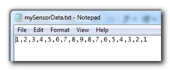
style="color: rgb(163, 21, 21);">"d:/mySensorData.txt"
);
String lineItems[]=splitTokens(textFileLines[0],
style="color: rgb(163, 21, 21);">","
);
numItems=lineItems.length;

style="color: rgb(0, 0, 255);">for
(
style="color: rgb(43, 145, 175);">int
i = counter; i<numItems; i++){
comPort.write(lineItems[i]);
delay(500);
comPort.write(
style="color: rgb(163, 21, 21);">"0"
);
}
counter=numItems;
}
}


ScottC 09 May 14:09