Posts with «project» label
433 MHz RF module with Arduino Tutorial 4:
WARNING: Please check whether you can legally use RF transmitters and receivers at your location before attempting this project (or buying the components). This project is aimed at those who are looking to automate their home.
Carrying on from my previous "433MHz transmitter and receiver" tutorials (1,2 & 3): I have thrown away the need to process the signal with a computer. This means that we can now get the Arduino to record the signal from an RF remote (in close proximity), and play it back in no time at all.
The Arduino will forget the signal when powered down or when the board is reset. The Arduino does not have an extensive memory - there is a limit to how many signals can be stored on the board at any one time. Some people have opted to create a "code" in their projects to help maximise the number of signals stored on the board. In the name of simplicity, I will not encode the signal like I did in my previous tutorials.
I will get the Arduino to record the signal and play it back - with the help of a button. The button will help manage the overall process, and control the flow of code.
Apart from uploading the sketch to the Arduino, this project will not require the use of a computer. Nor will it need a sound card, or any special libraries. Here are the parts required:
Parts Required:
- Arduino UNO or compatible board
- Breadboard
- Button
- Red and Green LED
- 330 ohm resistor(s)
- Wires
- RF Module (433 Mhz) - Transmitter and Receiver pair or the 315 Mhz version
- Mercator Ceiling Fan/Light with Remote
Fritzing Sketch
Arduino Sketch
1 |
|
Now let's see this project in action !
Have a look at the video below to see the Arduino turning a light and fan on/off shortly after receiving the RF signal from the RF remote. The video will also show you how to put this whole project together - step by step.
The Video

Please let me know whether this worked for you or not.
I have not tested this project with other remotes or other frequencies - so would be interested to find out whether this technique can be used for ALL RF projects ??
Loading...

Visit my ArduinoBasics Google + page.
Follow me on Twitter by looking for ScottC @ArduinoBasics.
Have a look at my videos on my YouTube channel.

However, if you do not have a google profile...
Feel free to share this page with your friends in any way you see fit.
433 MHz RF module with Arduino Tutorial 4:
- Part 1: Testing the 433 MHz RF transmitter and receiver
- Part 2: Receive and interpret code from an RF remote
- Part 3: Transmit a known 433 Mhz RF code to a 433 Mhz RF device
- Part 4: Record and play back a 433 Mhz RF remote signal - ** you are here **
Project 4 : 433 Mhz RF remote replacement tutorial
Carrying on from my previous "433MHz transmitter and receiver" tutorials (1,2 & 3): I have thrown away the need to process the signal with a computer. This means that we can now get the Arduino to record the signal from an RF remote (in close proximity), and play it back in no time at all.The Arduino will forget the signal when powered down or when the board is reset. The Arduino does not have an extensive memory - there is a limit to how many signals can be stored on the board at any one time. Some people have opted to create a "code" in their projects to help maximise the number of signals stored on the board. In the name of simplicity, I will not encode the signal like I did in my previous tutorials.
I will get the Arduino to record the signal and play it back - with the help of a button. The button will help manage the overall process, and control the flow of code.
Apart from uploading the sketch to the Arduino, this project will not require the use of a computer. Nor will it need a sound card, or any special libraries. Here are the parts required:
Parts Required:
- Arduino UNO or compatible board
- Breadboard
- Button
- Red and Green LED
- 330 ohm resistor(s)
- Wires
- RF Module (433 Mhz) - Transmitter and Receiver pair
- Mercator Ceiling Fan/Light with Remote
Fritzing Sketch
Arduino Sketch
Now let's see this project in action !
Have a look at the video below to see the Arduino turning a light and fan on/off shortly after receiving the RF signal from the RF remote. The video will also show you how to put this whole project together - step by step.
The Video

Please let me know whether this worked for you or not.
I have not tested this project with other remotes or other frequencies - so would be interested to find out whether this technique can be used for ALL RF projects ??

Visit my ArduinoBasics Google + page.
Follow me on Twitter by looking for ScottC @ArduinoBasics.
Have a look at my videos on my YouTube channel.

Feel free to share this page with your friends in any way you see fit.
433 MHz RF module with Arduino Tutorial 3
Project 3: RF Remote Control Emulation
Code comparison table
The RF remote that I am using transmits the same signal 6 times in a row. The signal to turn the light on is different from that used to turn the light off. In tutorial 2, we were able to "listen to" or receive the signal from the RF remote using the RF receiver. I thought it would be possible to just play back the signal received on the Arduino's analogPin, but the time it takes to perform a digital write is different to the time it takes to do an AnalogRead. Therefore it won't work. You need to slow down the digitalWrite speed.
I would like to find out if it is possible to apply this delay to all 433 MHz signal projects, however, I only have one 433 MHz remote.
If the delay in your project is the same as mine (or different) I would be keen to know - please leave a comment at the end of the tutorial.
We are going to use trial and error to find the optimal digitalWrite delay time. We will do this by slowly incrementing the delay until the transmission is successful. The transmission is considered successful if the fan-light turns on/off. All we have to do is count the number of transmissions until it is successful, then we should be able to calculate the delay.
Parts Required
- Arduino UNO or compatible board
- Breadboard
- Wires
- RF Module (433 Mhz) - Transmitter and Receiver pair or the 315 Mhz version
- Mercator Ceiling Fan/Light with Remote
The Transmitter Fritzing Sketch
RF Calibration - Arduino Sketch
1 | /* |
The short and long lengths were identified from the experiments performed in tutorial 2 (using the RF receiver). Each code is transmitted 6 times. The LED is turned on at the beginning of each transmission, and then turned off at the end of the transmission. The timeDelay variable starts at 5 microseconds, and is incremented by 10 microseconds with every transmission.
In the video, you will notice that there is some flexibility in the timeDelay value. The Mercator Fan/Light will turn on and off when the timeDelay variable is anywhere between 75 and 135 microseconds in length. It also seems to transmit successfully when the timeDelay variable is 175 microseconds.
So in theory, if we want to transmit a signal to the fan/light, we should be able to use any value between 75 and 135, however in future projects, I think I will use a value of 105, which is right about the middle of the range.

Video
Now that I have the timeDelay variable, I should be able to simplify the steps required to replicate a remote control RF signal. Maybe there is room for one more tutorial on this topic :)
Update: Here it is - tutorial 4
Where you can record and playback an RF signal (without using your computer).

433 MHz RF module with Arduino Tutorial 3
- Part 1: Testing the 433 MHz RF transmitter and receiver
- Part 2: Receive and interpret code from an RF remote
- Part 3: Transmit a known 433 Mhz RF code to a 433 Mhz RF device - ** you are here **
- Part 4: Record and play back a 433 Mhz RF remote signal
Project 3: RF Remote Control Emulation
Code comparison table
The RF remote that I am using transmits the same signal 6 times in a row. The signal to turn the light on is different from that used to turn the light off. In tutorial 2, we were able to "listen to" or receive the signal from the RF remote using the RF receiver. I thought it would be possible to just play back the signal received on the Arduino's analogPin, but the time it takes to perform a digital write is different to the time it takes to do an AnalogRead. Therefore it won't work. You need to slow down the digitalWrite speed.
I would like to find out if it is possible to apply this delay to all 433 MHz signal projects, however, I only have one 433 MHz remote.
If the delay in your project is the same as mine (or different) I would be keen to know - please leave a comment at the end of the tutorial.
We are going to use trial and error to find the optimal digitalWrite delay time. We will do this by slowly incrementing the delay until the transmission is successful. The transmission is considered successful if the fan-light turns on/off. All we have to do is count the number of transmissions until it is successful, then we should be able to calculate the delay.
Parts Required
- Arduino UNO or compatible board
- Breadboard
- Wires
- RF Module (433 Mhz) - Transmitter and Receiver pair
- Mercator Ceiling Fan/Light with Remote
The Transmitter Fritzing Sketch
RF Calibration - Arduino Sketch
The short and long lengths were identified from the experiments performed in tutorial 2 (using the RF receiver). Each code is transmitted 6 times. The LED is turned on at the beginning of each transmission, and then turned off at the end of the transmission. The timeDelay variable starts at 5 microseconds, and is incremented by 10 microseconds with every transmission.
In the video, you will notice that there is some flexibility in the timeDelay value. The Mercator Fan/Light will turn on and off when the timeDelay variable is anywhere between 75 and 135 microseconds in length. It also seems to transmit successfully when the timeDelay variable is 175 microseconds.
So in theory, if we want to transmit a signal to the fan/light, we should be able to use any value between 75 and 135, however in future projects, I think I will use a value of 105, which is right about the middle of the range.

Video
Now that I have the timeDelay variable, I should be able to simplify the steps required to replicate a remote control RF signal. Maybe there is room for one more tutorial on this topic :)
Update: Here it is - tutorial 4
Where you can record and playback an RF signal (without using your computer).

433 MHz RF module with Arduino Tutorial 2
Project 2: RF Remote Copy
In this project - we aim to receive a signal from an RF remote. The remote that I am using is a Mercator Remote Controller for a Fan/Light. (Remote controller code is FRM94). It is important that you use a remote that transmits at the same frequency as your receiver. In this case, my remote just happens to use a frequency of 433MHz. I was able to receive RF signals from from a distance of about 30cm without an antenna (from my remote to the receiver).
Video

Here are the parts that you will need to carry out this project:
Parts Required
- 1 x Arduino UNO or compatible board
- Breadboard
- Wires
- Mercator FRM94 Remote Controller for Fan/Light (Transmitter Model: TR107A)
- RF Module (433 Mhz) - Receiver or the 315 Mhz version
Remote Controller
You can quickly test your remote, by pressing one of the buttons in close proximity to the RF receiver (using the same sketch as in Project 1), and you should see the LED flicker on an off in response to the button press. If you don't see the LED flickering, then this project will not work for you.
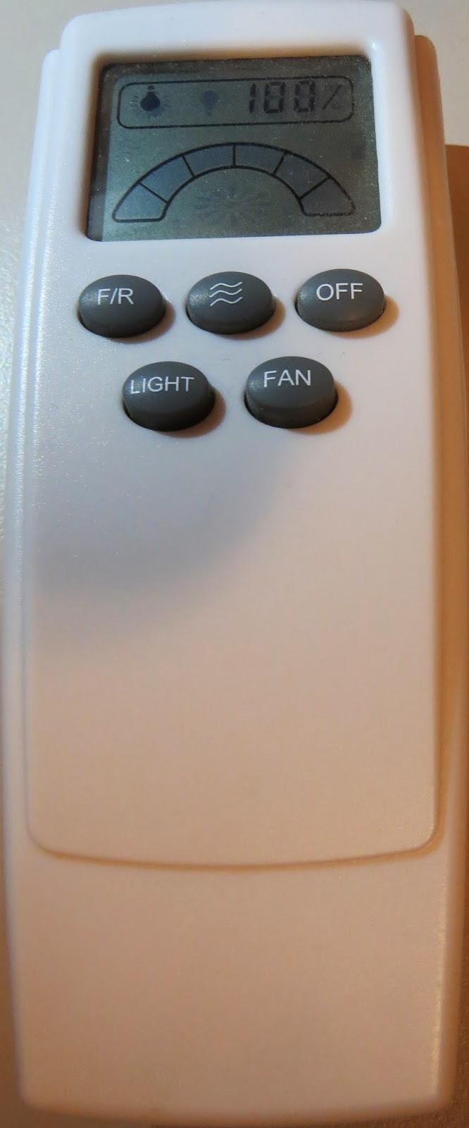
Here is a picture of the remote controller that I am using:
Arduino Sketch - Remote Receiver
The following sketch will make the Arduino wait until a signal is detected from the remote (or other 433 MHz RF device). Once triggered, it will turn the LED ON, and start to collect and store the signal data into an array.
I did my best to keep the signal reading section of the sketch free from other functions or interruptions.The aim is to get the Arduino to focus on reading ONLY... and once the reading phase is complete, it will report the signal data to the Serial monitor. So you will need to have the Serial monitor open when you press the remote control button.
The remote control signal will be made up of HIGH and LOW signals - which I will try to illustrate later in the tutorial. But for now, all you need to know is that the Signal will alternate between HIGH and LOW signals, and that they can be different lengths.
This sketch aims to identify how long each LOW and HIGH signal is (to make up the complete RF remote signal). I have chosen to capture 500 data points(or 250 LOW/HIGH combinations).You may wish to increase or decrease the dataSize variable to accomodate your specific RF signal. In my case, I only really needed 300 data points, because there was a "flat" signal for the last 200 data points (characterised by 200 repetitions of a LOW signal length of 0 and HIGH signal length of 255)
--------------------------------------------------
1 |
|
Receiver Fritzing Sketch
Results
After pressing the button on the RF remote, the data signal is printed to the Serial Monitor. You can copy the data to a spreadsheet program for review. This is an example of the signal produced after pushing the button on the remote for turning the fan/light on.| The following code was produced from pushing the button responsible for turning the light off: | |
| The code sequence above may seem a bit random until you start graphing it. I grabbed the LOW column - and produced the following chart: | |
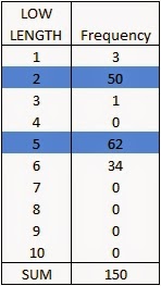
| The chart above is a bit messy - mainly because the timing is slightly out... in that sometimes it can squeeze an extra read from a particular signal. But what is important to note here is that you can differentiate a LONG signal from a SHORT signal. I have drawn a couple of red dotted lines where I believe most of the readings tend to sit. I then used a formula in the spreadsheet to calibrate the readings and make them a bit more uniform. For example, if the length of the signal was greater than 4 analogReads, then I converted this to 6. If it was less than 4 analogReads, then I converted it to 2. I used a frequency table to help decide on the cutoff value of 4, and just decided to pick the two values (2 for short, and 6 for long) based on the frequency tables below. I could have chosen 5 as the LONG value, but there were more 6's overall. **The meaning of "frequency" in the following tables relate to the "number of times" a specific signal length is recorded. | |
And this is the resulting chart: | |
You will notice that the pattern is quite repetitive. I helped to identify the sections with vertical red lines (near the bottom of the chart). In other words, the signal produced by the remote is repeated 6 times. I then did the same for the HIGH signal column and combined the two to create the following chart: | |
| | |
| You will notice that the HIGH signals also have a repetitive pattern, however have a Very long length at the end of each section. This is almost a break to separate each section. This is what a single section looks like zoomed in: | |
SL = [Short LOW] signal. - or short blue bar SH = [Short HIGH] signal - or short yellow bar LL = [Long LOW] signal - or long blue bar LH = [Long HIGH] signal - or long yellow bar VLH = [Very long HIGH} signal - or very long yellow bar (~92 analogReads in length) You will notice that there are only about 6 different combinations of the signals mentioned above. We can use this to create a coding system as described below: | |
| | |
| We can use this coding system to describe the signals. The charts below show the difference between turning the LIGHT ON and LIGHT OFF. | |
| | |
| | |
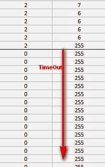
| PLEASE NOTE: You may notice when you copy the signals from the Serial monitor that you get a series of (0,255) combinations. This is actually a timeout sequence - which generally occurs after the signal is complete. Here is an example of what I mean. | |

This is the end of tutorial 2. In the next tutorial, we will use the code acquired from the remote to turn the FAN LIGHT on and off (using the 433 MHz RF transmitter).
Click here for Tutorial 3
433 MHz RF module with Arduino Tutorial 2
There are 4 parts to this tutorial:
- Part 1: Testing the 433 MHz RF transmitter and receiver
- Part 2: Receive and interpret code from an RF remote - ** you are here **
- Part 3: Transmit a known 433 Mhz RF code to a 433 Mhz RF device
- Part 4: Record and play back a 433 Mhz RF remote signal
Project 2: RF Remote Copy
In this project - we aim to receive a signal from an RF remote. The remote that I am using is a Mercator Remote Controller for a Fan/Light. (Remote controller code is FRM94). It is important that you use a remote that transmits at the same frequency as your receiver. In this case, my remote just happens to use a frequency of 433MHz. I was able to receive RF signals from from a distance of about 30cm without an antenna (from my remote to the receiver).
Video

Here are the parts that you will need to carry out this project:
Parts Required
- 1 x Arduino UNO or compatible board
- Breadboard
- Wires
- Mercator FRM94 Remote Controller for Fan/Light (Transmitter Model: TR107A)
- RF Module (433 Mhz) - Receiver
Remote Controller
You can quickly test your remote, by pressing one of the buttons in close proximity to the RF receiver (using the same sketch as in Project 1), and you should see the LED flicker on an off in response to the button press. If you don't see the LED flickering, then this project will not work for you.
Here is a picture of the remote controller that I am using:
Arduino Sketch - Remote Receiver
I did my best to keep the signal reading section of the sketch free from other functions or interruptions.The aim is to get the Arduino to focus on reading ONLY... and once the reading phase is complete, it will report the signal data to the Serial monitor. So you will need to have the Serial monitor open when you press the remote control button.
The remote control signal will be made up of HIGH and LOW signals - which I will try to illustrate later in the tutorial. But for now, all you need to know is that the Signal will alternate between HIGH and LOW signals, and that they can be different lengths.
This sketch aims to identify how long each LOW and HIGH signal is (to make up the complete RF remote signal). I have chosen to capture 500 data points(or 250 LOW/HIGH combinations).You may wish to increase or decrease the dataSize variable to accomodate your specific RF signal. In my case, I only really needed 300 data points, because there was a "flat" signal for the last 200 data points (characterised by 200 repetitions of a LOW signal length of 0 and HIGH signal length of 255)
--------------------------------------------------
Receiver Fritzing Sketch
Results
After pressing the button on the RF remote, the data signal is printed to the Serial Monitor. You can copy the data to a spreadsheet program for review. This is an example of the signal produced after pushing the button on the remote for turning the fan/light on.| The following code was produced from pushing the button responsible for turning the light off: | |
| The code sequence above may seem a bit random until you start graphing it. I grabbed the LOW column - and produced the following chart: | |
| The chart above is a bit messy - mainly because the timing is slightly out... in that sometimes it can squeeze an extra read from a particular signal. But what is important to note here is that you can differentiate a LONG signal from a SHORT signal. I have drawn a couple of red dotted lines where I believe most of the readings tend to sit. I then used a formula in the spreadsheet to calibrate the readings and make them a bit more uniform. For example, if the length of the signal was greater than 4 analogReads, then I converted this to 6. If it was less than 4 analogReads, then I converted it to 2. I used a frequency table to help decide on the cutoff value of 4, and just decided to pick the two values (2 for short, and 6 for long) based on the frequency tables below. I could have chosen 5 as the LONG value, but there were more 6's overall. **The meaning of "frequency" in the following tables relate to the "number of times" a specific signal length is recorded. | |
And this is the resulting chart: | |
You will notice that the pattern is quite repetitive. I helped to identify the sections with vertical red lines (near the bottom of the chart). In other words, the signal produced by the remote is repeated 6 times. I then did the same for the HIGH signal column and combined the two to create the following chart: | |
| You will notice that the HIGH signals also have a repetitive pattern, however have a Very long length at the end of each section. This is almost a break to separate each section. This is what a single section looks like zoomed in: | |
SL = [Short LOW] signal. - or short blue bar SH = [Short HIGH] signal - or short yellow bar LL = [Long LOW] signal - or long blue bar LH = [Long HIGH] signal - or long yellow bar VLH = [Very long HIGH} signal - or very long yellow bar (~92 analogReads in length) You will notice that there are only about 6 different combinations of the signals mentioned above. We can use this to create a coding system as described below: | |
| We can use this coding system to describe the signals. The charts below show the difference between turning the LIGHT ON and LIGHT OFF. | |
| PLEASE NOTE: You may notice when you copy the signals from the Serial monitor that you get a series of (0,255) combinations. This is actually a timeout sequence - which generally occurs after the signal is complete. Here is an example of what I mean. | |

This is the end of tutorial 2. In the next tutorial, we will use the code acquired from the remote to turn the FAN LIGHT on and off (using the 433 MHz RF transmitter).
Click here for Tutorial 3
433 MHz RF module with Arduino Tutorial 1
- Part 1: Testing the 433 MHz RF transmitter and receiver <- are="" here="" li="" you="">
- Part 2: Receive and interpret code from an RF remote
- Part 3: Transmit a known 433 Mhz RF code to a 433 Mhz RF device
- Part 4: Record and play back a 433 Mhz RF remote signal
- Virtual Wire (at ICStation)
- RadioHead - which supercedes VirtualWire
- RC-Switch for communication with remote controls
- Ninjablocks 433 Utilities
I will mention at this point however, that I did NOT use any libraries in this particular tutorial. That's right. I will show how easy it is to transmit data from one arduino to another using these RF modules WITHOUT libraries.
Also if you are looking for an easy way to record the signals and play them back without a computer - then jump to this tutorial.
Video

Project 1- RF Blink
Here are the parts that you will need to carry out this project:
Parts Required
- 2 x Arduino UNO or compatible boards
- Breadboard
- Wires
- RF Module (433 Mhz) - Transmitter and Receiver pair
The Transmitter and Receiver Fritzing Sketch
The Transmitter
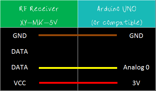
The transmitter has 3 pins  | 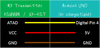 |
Notice the pin called "ATAD". It took me a while to figure out what ATAD stood for, when I suddenly realised that this was just a word reversed. It should be DATA (not ATAD). Nevertheless, this is the pin responsible for transmitting the signal. We will make the Arduino's onboard LED illuminate when the transmitter pin is HIGH, and go off when LOW as described in the following table.

And this is the Arduino Sketch to carry out the data transmission.
Arduino sketch - Transmitter
The Receiver
If all goes to plan, the onboard LED on this Arduino should light up (and go off) at the same time as the onboard LED on the transmitting Arduino. There is a chance that the receiver may pick up stray signals from other transmitting devices using that specific frequency. So you may need to play around with the threshold value to eliminate the "noise". But don't make it too big, or you will eliminate the signal in this experiment. You will also notice a small delay between the two Arduinos. |
Arduino sketch - Receiver
When a HIGH signal is transmitted to the other Arduino. It will produce an AnalogRead = 0.
When a LOW signal is transmitted, it will produce an AnalogRead = 400.
This may vary depending on on your module, and voltage used.
The signals received can be viewed using the Serial Monitor, and can be copied into a spreadsheet to create a chart like this:

Tutorial 2
In tutorial 2, we will receive and display a signal from a Mercator RF Remote Controller for Fan/Light.Tutorial 3
In tutorial 3 - we use the signal acquired from tutorial 2, and transmit the signal to the fan/light to turn the light on and off.Tutorial 4
In tutorial 4 - we use the information gathered in the first 3 tutorials and do away with the need for a computer. We will listen for a signal, store the signal, and then play it back by pressing a button. Similar to a universal remote ! No libraries, no sound cards, no computer. Just record signal and play it back. Awesome !!
Visit my ArduinoBasics Google + page.
Follow me on Twitter by looking for ScottC @ArduinoBasics.
Have a look at my videos on my YouTube channel.

Feel free to share this page with your friends in any way you see fit.
433 MHz RF module with Arduino Tutorial 1
- Virtual Wire (at ICStation)
- RadioHead - which supercedes VirtualWire
- RC-Switch for communication with remote controls
- Ninjablocks 433 Utilities
I will mention at this point however, that I did NOT use any libraries in this particular tutorial. That's right. I will show how easy it is to transmit data from one arduino to another using these RF modules WITHOUT libraries.
Also if you are looking for an easy way to record the signals and play them back without a computer - then jump to this tutorial.
Video

Project 1- RF Blink
Here are the parts that you will need to carry out this project:
Parts Required
- 2 x Arduino UNO or compatible boards
- Breadboard
- Wires
- RF Module (433 Mhz) - Transmitter and Receiver pair or the 315 Mhz version
The Transmitter and Receiver Fritzing Sketch
The Transmitter
| The transmitter has 3 pins, | |
| Notice the pin called "ATAD". It took me a while to figure out what ATAD stood for, when I suddenly realised that this was just a word reversed. It should be DATA (not ATAD). Nevertheless, this is the pin responsible for transmitting the signal. We will make the Arduino's onboard LED illuminate when the transmitter pin is HIGH, and go off when LOW as described in the following table. And this is the Arduino Sketch to carry out the data transmission. |
Arduino sketch - Transmitter
1 | /* |
The Receiver
If all goes to plan, the onboard LED on this Arduino should light up (and go off) at the same time as the onboard LED on the transmitting Arduino. There is a chance that the receiver may pick up stray signals from other transmitting devices using that specific frequency. So you may need to play around with the threshold value to eliminate the "noise". But don't make it too big, or you will eliminate the signal in this experiment. You will also notice a small delay between the two Arduinos. |
Arduino sketch - Receiver
1 | /* |
When a HIGH signal is transmitted to the other Arduino. It will produce an AnalogRead = 0.
When a LOW signal is transmitted, it will produce an AnalogRead = 400.
This may vary depending on on your module, and voltage used.
The signals received can be viewed using the Serial Monitor, and can be copied into a spreadsheet to create a chart like this:

Tutorial 2
In tutorial 2, we will receive and display a signal from a Mercator RF Remote Controller for Fan/Light.Tutorial 3
In tutorial 3 - we use the signal acquired from tutorial 2, and transmit the signal to the fan/light to turn the light on and off.Tutorial 4
In tutorial 4 - we use the information gathered in the first 3 tutorials and do away with the need for a computer. We will listen for a signal, store the signal, and then play it back by pressing a button. Similar to a universal remote ! No libraries, no sound cards, no computer. Just record signal and play it back. Awesome !! 
Visit my ArduinoBasics Google + page.
Follow me on Twitter by looking for ScottC @ArduinoBasics.
Have a look at my videos on my YouTube channel.

However, if you do not have a google profile...
Feel free to share this page with your friends in any way you see fit.
Project – Arduino “Book Monster”
Introduction
Recently we saw a neat project by the people from Evil Mad Scientist – their “Peek-O-Book“, a neat take on a book with a shy monster inside, based on hardware from their Snap-O-Lantern kit. Not wanting to fork out for the postage to Australia we decided to make our own version, of which you can follow along.
This is a fun project that doesn’t require too much effort and has a lot of scope for customisation. There’s no right or wrong when making your own (or this one!) so just have fun with it.
Construction
First, you’ll need a book of some sort, something large enough to hide the electronics yet not too large to look “suspicious” – then cut the guts out to make enough space for the electronics. Then again it’s subjective, so get whatever works for you. Coincidentally we found some “dummy books” (not books for dummies) that were perfect for the job:

After spraying the inside with matt black paint, the inside is better suited for the “eyes in the dark” effect required for the project:

The “book” had a magnet and matching metal disk on the flap to aid with keep the cover shut, however this was removed as it will not allow for smooth opening with the servo.
The electronics are quite simple if you have some Arduino or other development board experience. Not sure about Arduino? You can use any microcontroller that can control a servo and some LEDs. We’re using a Freetronics LeoStick as it’s really small yet offers a full Arduino Leonardo-compatible experience, and a matching Protostick to run the wires and power from:
By fitting all the external wiring to the Protostick you can still use the main LeoStick for other projects if required. The power is from 4 x AA cells, with the voltage reduced with a 1n4004 diode:
And for the “eyes” of our monster – you can always add more if it isn’t too crowded in the book:
We’ll need a resistor as well for the LEDs. As LEDs are current driven you can connect two in series with a suitable dropping resistor which allows you to control both if required with one digital output pin. You can use the calculator here to help determine the right value for the resistor.
Finally a servo is required to push the lid of the book up and down. We used an inexpensive micro servo that’s available from Tronixlabs:
The chopsticks are cut down and used as an extension to the servo horn to give it more length:
Don’t forget to paint the arm black so it doesn’t stand out when in use. We had a lazy attack and mounted the servo on some LEGO bricks held in with super glue, but it works. Finally, here is the circuit schematic for our final example – we also added a power switch after the battery pack:
To recap – this is a list of parts used:
- Dummy book
- Freetronics LeoStick and Protostick
- micro 9G servo
- two 5mm LEDs
- one 68Ω or thereabouts resistor
- assorted wire
- 9V battery snap (used as some 4 x AA cell holders need this)
- 4 x AA cell battery holder and 4 x AA cells
- SPDT switch
- 1N4004 or similar rectifier diode
- box, chopstick, odds and ends to mount the hardware
After some delicate soldering the whole lot fits neatly in the box:
Arduino Sketch
The behaviour of your “book monster” comes down to your imagination. Experiment with the servo angles and speed to simulate the lid opening as if the monster is creeping up, or quickly for a “pop-up” surprise. And again with the LED eyes you can blink them and alter the brightness with PWM. Here’s a quick sketch to give you an idea:
int angle;
int d; // for delays
int ledPin = 9; // LEDs on digital pin 9

#include <Servo.h>
Servo myservo;

void setup()
{
  myservo.attach(4); // servo control pin on digital 4
  pinMode(9, OUTPUT);
  randomSeed(analogRead(0));
  myservo.write(10);
  delay(5000);
}

void behaviour1()
{
  for (angle = 10; angle <=40; angle++)
  {
    myservo.write(angle);
    delay(50);
  }
  digitalWrite(ledPin, HIGH);
  delay(250);
  digitalWrite(ledPin, LOW);
  delay(250);
  digitalWrite(ledPin, HIGH);
  delay(250);
  digitalWrite(ledPin, LOW);
  delay(250);
  digitalWrite(ledPin, HIGH);
  delay(1000);
  digitalWrite(ledPin, LOW);
  delay(250);
  digitalWrite(ledPin, HIGH);
  delay(1000);
  digitalWrite(ledPin, LOW);
  delay(250);
  digitalWrite(ledPin, HIGH);
  delay(1000);
  digitalWrite(ledPin, LOW);
  delay(250);
  for (angle = 40; angle >=10; --angle)
  {
    myservo.write(angle);
    delay(5);
  }
}

void loop()
{
  behaviour1();
  delay(random(60000));
}
You can watch our example unit in this video.
Frankly the entire project is subjective, so just do what you want.
Conclusion
Well that was fun, and I am sure this will entertain many people. A relative is a librarian so this will adorn a shelf and hopefully give the children a laugh. Once again, thanks to the people from Evil Mad Science for the inspiration for this project – so go and buy something from their interesting range of kits and so on.
And if you enjoyed this article, or want to introduce someone else to the interesting world of Arduino – check out my book (now in a third printing!) “Arduino Workshop”.
The post Project – Arduino “Book Monster” appeared first on tronixstuff.


