Posts with «lamp» label

HDD Centrifuge Puts COVID-19 Testing Lab in a Backpack

Throughout this two-year global COVID-19 nightmare, one thing that has been sorely lacking is access to testing. “Flu-like symptoms” covers a lot of ground, and knowing if a sore throat is just a sore throat or something more is important enough that we’ve collectively plowed billions into testing. Unfortunately, the testing infrastructure remains unevenly distributed, which is a problem this backpack SARS-CoV-2 testing lab aims to address.

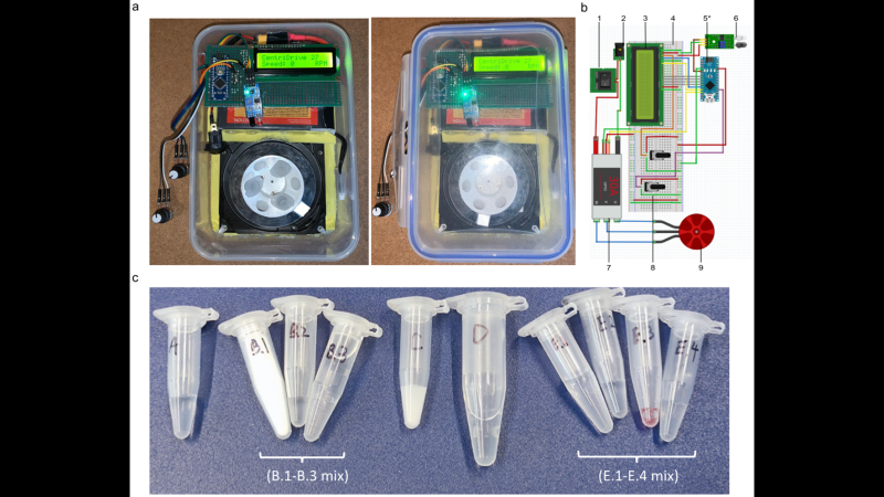
The portable lab, developed by [E. Emily Lin] and colleagues at the Queen Mary University of London, uses a technique called LAMP, for loop-mediated isothermal amplification. LAMP probably deserves an article of its own to explain the process, but suffice it to say that like PCR, LAMP amplifies nucleic acid sequences, but does so without the need for expensive thermal cycling equipment. The kit contains a microcentrifuge that’s fashioned from an e-waste hard drive, a 3D printed rotor, and an Arduino to drive the motor and control the speed. The centrifuge is designed to run on any 12 VDC source, meaning the lab can be powered by a car battery or solar panel if necessary. Readout relies on the trusty Mark I eyeball and a pH-indicating buffer that changes color depending on how much SARS-CoV-2 virus was in the sample.

Granted, the method used here still requires more skill to perform than a simple “spit on a stick” rapid antigen test, and it’s somewhat more subjective than the “gold standard” quantitative polymerase chain reaction (qPCR) assay. But the method is easily learned, and the kit’s portability, simple design, and low-cost construction could make it an important tool in attacking this pandemic, or the next one.

Thanks to [Christian Himmler] for the tip.

Man Shoots Lamp

What do you get when you mix together all of the stuff that you can get for cheap over eBay with a bit of creativity and some PVC pipe? [Austiwawa] gets a table lamp, remote-controlled by a toy gun, that turns off and falls over when you shoot it. You’ve got to watch the video below the break.

This isn’t a technical hack. Rather it’s a creative use of a bunch of easily available parts, with a little cutting here and snipping there to make it work. For instance, [Austiwawa] took a remote control sender and receiver pair straight off the rack and soldered some wires to extend the LED and fit it inside the toy gun. A relay module controls the lamp, and plugs straight into the Arduino that’s behind everything. Plug and play.

Which is not to say the lamp lacks finesse. We especially like the screw used as an end-of-travel stop for the servo motor, and the nicely fabricated servo bracket made from two Ls. And you can’t beat the fall-over-dead effect. Or can you? Seriously, though, great project [Austiwawa]!


Filed under: home hacks

Staying focused with a brain-sensing smart lamp

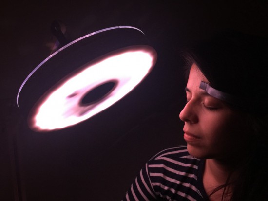
Clara is a smart lamp able to respond to your brain waves and subtly adjust your environment. The project, running on Arduino Uno, was created by  Marcelo Mejía Cobo, Belen Tenorio, and Josh Sucher for a class at the School of Visual Arts in NYC (US).

The team worked with the Neurosky MindWave Mobile, a Bluetooth EEG-reading headset in order to wirelessly detect “attention” and map the lamp’s color temperature and speaker volume accordingly:

At first, the lamp emits a warm, comforting glow, conducive to idea generation and creativity. But as you start homing in on a specific idea, the light becomes crisper and cooler, and the volume of the ambient noise flowing from the embedded speaker slowly increases, enhancing your ability to concentrate and block out external distractions.

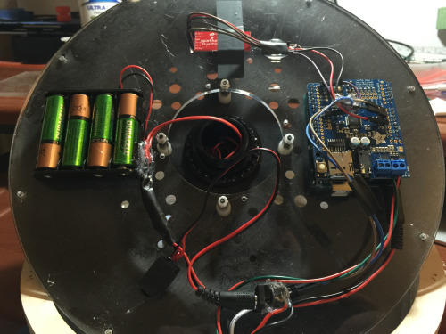
In the picture below you can see the inside of the lamp with the Arduino Uno and Adafruit Music Maker shield:

Explore the Arduino Sketch on Github.

Arduino Blog 09 Oct 23:19

New dimmer software

Based on the success of the stroboscope software, I rewrote the dimmer software for my desk lamp (see LED lamp projects for more about the lamps).  The new software provides smoother control of the light levels (having 256 levels plus off, rather than 63 levels plus off) and now has a 256:1 brightness range rather than the approximately 256:6 range of the previous code.

I removed a lot of the general-purpose crap that was inherited from core13 (which was in turn stripped down from the Arduino core software).  I did not get rid of all of core13, so I could probably take out another 50–100 bytes, but the code is down to 222 bytes (and the ATtiny13A has 1kB of flash, so I’m way below the limit).

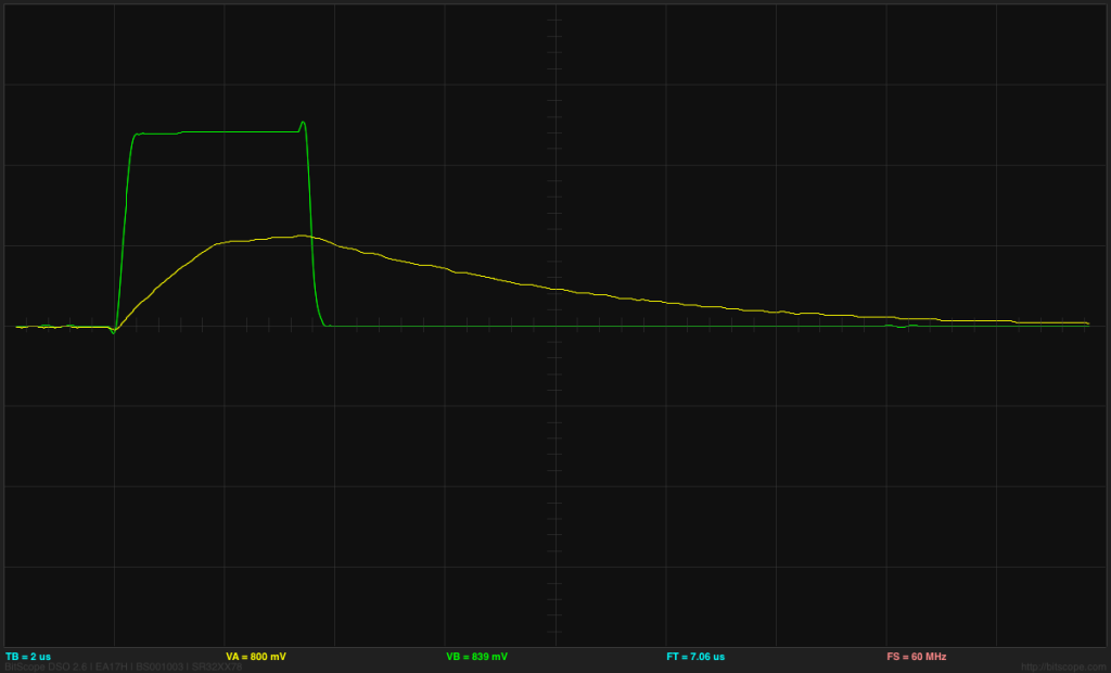
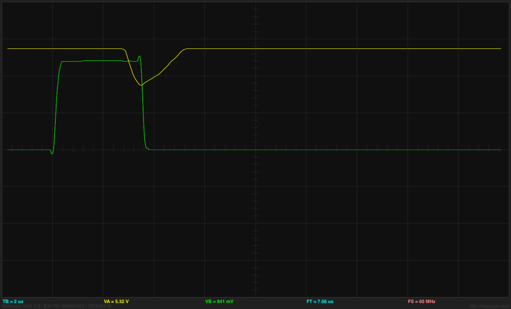
The actual brightness range of the new dimmer is a bit more than 256:1, because on the shortest pulse the FET doesn’t turn all the way on.  The pulse duration from the ATtiny13A is approximately 3.4µs times the brightness level (9.6MHz clock divided down by 4 and by 8), but I had deliberately slowed the FET transitions by adding a series resistor to the gate, so that nFET doesn’t finish turning on for 5.2µs (as judged by the end of the Miller plateau on the gate).  So at the lowest brightness level, the nFET does not turn all the way on and the voltage on the drain only gets down to 3.5V, which leaves 5.5V across the LED board—enough to turn on the LED, but with only about 10mA, not 118mA. At this low level, the LEDs sometimes flicker, perhaps as a result of some thermal feedback effects. The all flicker together, so the effect is probably in the dimmer’s nFET, not on the LED boards.

ATtiny output (green) and gate voltage (yellow) at 2V/division and 2µs/division for the shortest pulse length. The gate voltage has not quite reached the end of the Miller plateau before being discharged again.

ATtiny output (green) and drain voltage (yellow) at 2V/division and 2µs/division for the shortest pulse length. The BitScope BS-10 oscilloscope clips the voltage to 5.5V—it actually goes to 9V.

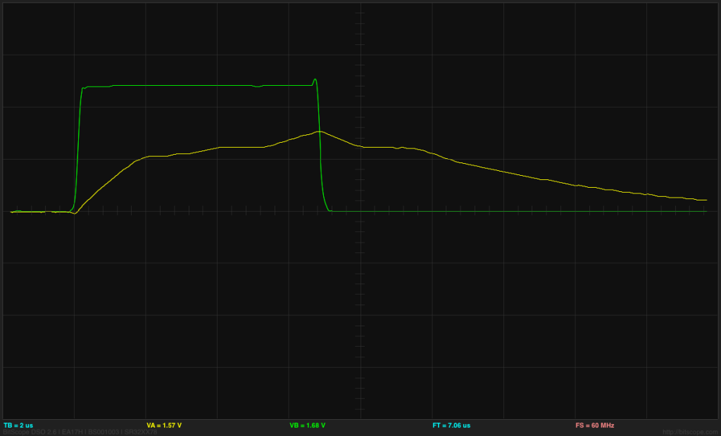
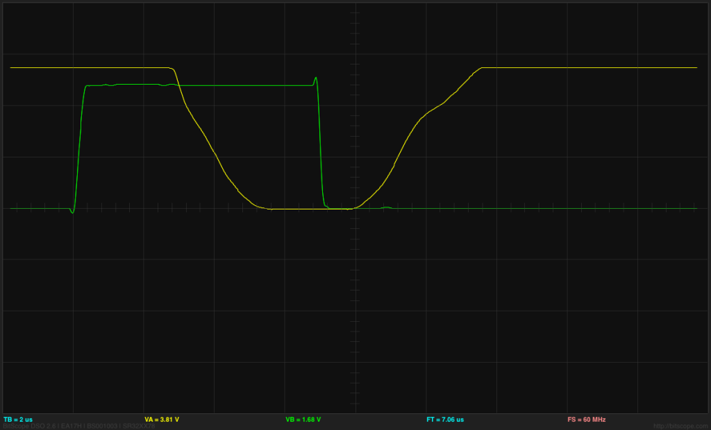
At the next brightness level, the drain voltage does drop to 0V for at least 2.4µs and stays low enough for the LED board to be at maximum current (below 2.5V) for at least 5.5µs.  There is an enormous difference in brightness between length 2 and length 1 pulses (more like 1:20 than 1:2), because of the low current for pulse length 1, but for length 2 and longer the steps in brightness are pretty much as one would expect from the pulse lengths.

ATtiny output (green) and gate voltage (yellow) at 2V/division and 2µs/division for the shortest pulse length. The gate voltage has gone past the end of the Miller plateau and started charging past that point. The Miller plateau is also visible on the discharge as the nFET turns off.

ATtiny output (green) and drain voltage (yellow) at 2V/division and 2µs/division for the second shortest pulse length. The BitScope BS-10 oscilloscope clips the voltage to 5.5V—it actually goes to 9V.
The longer pulses allow the nFET to turn on fully.

The conversion from the linear 10-bit analog-to-digital reading (0–1023) to pulse lengths is done by the following method:

expon = ADC>>7
frac = 0x80 + (ADC & 0x7f)
pulse_len = ADC < 0x20? 0:  ADC < 0x40? 1: 1+ (frac>> (7-expon))

The stepwise nature of the brightness at low levels is apparent in a plot of the conversion function:

The steps in brightness are quite visible at the low end, but after the first 10 steps, the differences are small enough not to be easily noticed.

Overall, I’m pleased with the rework of the dimmer code. I’ll probably have to solder up another of the dimmer boards this summer, since I’ll want one for the light fixture that I haven’t started building yet and one for the Halloween stroboscope.


Filed under: Uncategorized Tagged: Arduino, ATtiny, BitScope, dimmable LED lamps, lamp, Miller plateau

LED strobe using dimmer board

In the evenings this week, I soldered up another PWM controller for the LED lamp projects, and programmed it with the ISP cable I made.  The intent was to use this dimmer either with the breakfast-room lighting fixture (which I’ve not made yet) or reprogram it to act as a strobe rather than a dimmer, to replace the Xenon-tube-based Velleman strobe kit that failed last Thanksgiving.

This project took me much longer than expected, because of stupid mistakes I made:

  • I forgot that there was a silkscreen error on the dimmer boards that I had designed.  The outline for the voltage regulator is flipped, because I had not noticed when reading the spec sheet shows the device from the bottom—I’m used to chip views being from the top.  This is the second time that I’ve soldered a voltage regulator on one of the boards backwards, and had to cut it off and replace it with a new one.  I guess I’d better take a permanent felt-tip marker and draw the correct orientation on the remaining boards, so that I don’t make that mistake a third time.
  • When playing with new code for the strobe, refamiliarizing myself with the ATtiny13A processor, I changed the prescaling on the system clock from the default 1.2MHz down to about 75kHz.  What I had not realized is that the on-chip clock is used during the reprogramming also, and the Arduino ISP is not set up for slowly clocked chips.  I found code for TinyISP, which has code for 128kHz clocks, but even when I modified it for 75kHz clocks I couldn’t reprogram the chip (always getting the “Yikes! invalid device signature” message with a signature of 0). Eventually, I gave up, unsoldered the ATtiny13A and put in a new one.  I’ll be very careful in future not to slow down the system clock so much.
  • I got the strobe working this morning, but when I looked at the output pin that was driving the FET gate, it was only going up to 1.3V, not 5V, and the pulse was much longer than I expected.  This mystified me for a while, but I finally realized that I had forgotten to turn the pin on as an output, so I was driving the output just through the built-in pullup resistor, resulting in a very large RC time constant.  The flat top I was seeing on the pulse was probably the Miller plateau.  Enabling the output pin correctly got me back to crisp 5V pulses of the designed duration.
  • The designed duration for the pulses was a bit too short, resulting in a somewhat dimmer than desired flash.  Lengthening the pulse to 1ms was fine for the slow strobes, but at high flash rates the strobe got too bright. So I reprogrammed the flashes so that the on-time was 1/64th of the off-time, but with a maximum on-time of 1.6ms. (I also tried on=off/128 with a maximum of 1ms, but I liked the 1/64 better).

I timed the strobe pulses from the board (looking at the output of the ATtiny13A pin 6, which is also connected to the MISO pin of the ISP header, so is easy to connect a jumper wire to) with PteroDAQ (through a voltage divider, to drop the voltage from 5V to 2.75V).  By triggering the PteroDAQ on edges of the signal, and averaging many measurements, I got very precise timing measurements:

setup on-time off-time
slowest setting, 1:64 1.63745ms 1.52372s
fastest setting, 1:64 104.958µs 6.98761ms
slowest setting, 1:128 955.277µs 1.55881s
fastest setting, 1:128 51.3123µs 6.99286ms

The difference in the “slowest” settings is probably just from my inability to set the knob identically—it has to be just above a threshold below which the strobe doesn’t flash at all. In any case, I have a period from 7.1ms (141Hz) to 1.525s (0.6556Hz), which is a pretty useful range.  I also made the range very smooth, by taking the 10-bit ADC range and converting it to this 215:1 range sort of exponentially with just a few instructions:

if adc<40, then OFF
exp = adc >> 7
frac = 0xff - (adc & 0x7f)
on_time = (frac << 8) >> exp
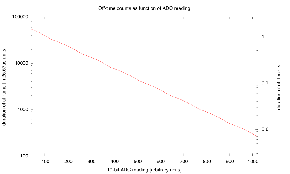
The tiny number of instructions provides a surprisingly smooth and strictly decreasing approximation to the desired exponential.

The transition is smooth because every time an increment increases the exponent, the frac part is doubled (from 0x80 to 0xff).I use a 16-bit word for the on_time and count it down with an interrupt once every 26.67µs (256 of the approximately 9.6MHz clock ticks). I think that I’ll do a similar thing for controlling the duty cycle of the dimmer, rather than the table of bytes that I currently use, though the duty cycle is limited to a single byte, so I’ll only have 256 levels, and not 1024, and I’ll want the duty cycle to increase exponentially, rather than decreasing, but those are easy fixes.

I also reduced the size of the program in flash, by getting rid of some of the overly general code from core13 and just manipulating the peripheral control registers directly.  I didn’t need to do this, as the ATtiny13A has 1kB of flash, but I got down to 364 bytes (and could probably strip out another 50–100 by getting rid of even more of core13).  The old dimmer code, which doesn’t have much more to do, currently takes 806 bytes, so I might try tightening that up tomorrow.

I also tried powering the strobe off a 9V battery.  The LED board takes about 117mA when turned on (see LED board I-vs-V curve), and if I keep the duty cycle below 1.5%, then the average current is dominated by the ATtiny13A’s worst-case 6mA current, and the total current for the board is probably less than 8mA.  According to Duracell’s data sheet for their 9V alkaline battery, I should be able to get about 50 hours of life before the voltage drops below 6.7V (at which point the LED board no longer maintains the constant current, but I could run the strobe a bit longer getting dimmer).  The 6.7V is also about the voltage where the LDO voltage regulator starts being unable to supply 5V to the ATtiny13A, though that is less of a bottleneck, as the chip can run with the 9.6MHz internal clock down to 3V with no problems.

The battery does not have to provide a full 117mA for the pulses, as there is a 470μF polymer electrolytic capacitor on the dimmer board.  Delivering 117mA for 1.6ms is only 187μC, so the voltage on the capacitor would dip at most 0.4V during the pulse, even without the battery.  The 9V battery has an internal resistance of 2Ω–4Ω, so it could provide 117mA with about a 0.35V drop, so the capacitor isn’t really necessary for one LED board.  It probably increases the efficiency slightly, as the I2R power loss in the internal resistor is reduced if the current is spread out (half the current for twice as long is only half the I2R loss).

I could put more LED boards on the strobe, as the dimmer is designed to handle 5A or more, but battery  operation would limit me to about 10 boards before the voltage drop was large enough to cause problems for the current regulation.  One LED board is bright enough for a Halloween pumpkin, but I could run wires between pumpkins to power several off the same controller.  (I could also keep the controller in the house, powered by a wall wart, and run wires out to the LED boards—I could then power 40 or 50 LED boards off the strobe, though I’d have to watch out for IR drop in the wiring.)

I might try wiring up 10 boards tomorrow, and see whether a battery really can power that many.


Filed under: Uncategorized Tagged: Arduino, Arduino as ISP, ATtiny, dimmable LED lamps, lamp, strobe, stroboscope

Arduino as ISP

For the LED lamp projects, I’ve been using ATtiny13A chips for the dimmer board, programmed with the Arduino IDE and an Arduino board as an In-System Programmer (ISP).  The Arduino code is too big for an ATtiny, so I’ve been using a version of the core13 stripped-down system.

I got rather tired of wiring up the 8 wires for the ISP, checking to make sure that each one was correct.  What I wanted to do was just plug in a standard 8-pin cable from the Arduino board to the ATtiny board, but the ISP header on the Arduino board has the Arduino reset line, not the reset line that has to go to the ATtiny board.

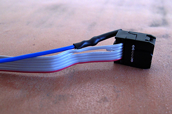
I decided to modify a standard cable to do the right thing, separating the reset line from the rest. The reset line is on pin 7, so on a standard ribbon cable, it is the seventh of the eight wires.

First I carefully cut wire 7 near one of the plugs with a razor knife, peeled it back and spliced on another piece of stranded wire:

The blue wire and wire 7 of the ribbon cable were soldered together and covered with heat-shrink tubing.

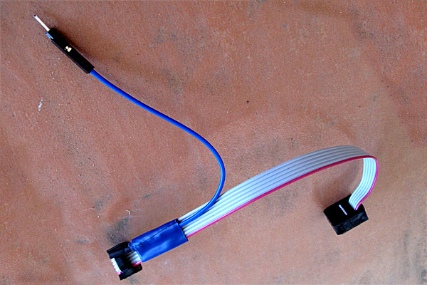
I taped the soldered joint to rest of the ribbon cable for strain relief, and added a crimp-on female header at the other end. (I prefer female crimp-on headers, because they are more versatile than male pin—I can stick in a double-ended male header pin to convert them to male connectors when needed.)

The electrical tape stabilizes the splice and the crimp-on female header allows connecting to male or female headers on the Arduino board. Here there is a double-ended male header pin in the female header, to convert it to a male header.

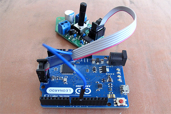
Here is a Leonardo board being used to program one of the dimmer boards:

With the new cable, it is easy to unplug the cable after programming to test out the system, then plug it back in with the right orientation (I used a shrouded header on the dimmer board) when reprogramming is needed.

Note that the reset line for the ISP cable connects to pin 10 of the programming Arduino board, which would be connected via a USB cable to the laptop that has the Arduino development environment on it.

I’ve seen several kluges on the web for connecting up Arduinos as ISPs, but none were as simple as and easy to use as what I did here, so I thought I ought to share it.


Filed under: Uncategorized Tagged: Arduino, Arduino as ISP, ATtiny, dimmable LED lamps, lamp

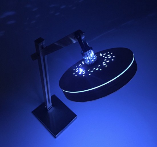
Sleek Desk Lamp Changes Colors Based on Sun Position

[Connor] was working on a project for his college manufacturing class when he came up with the idea for this sleek desk lamp. As a college student, he’s not fond of having his papers glowing brightly in front of him at night. This lamp takes care of the problem by adjusting the color temperature based on the position of the sun. It also contains a capacities touch sensor to adjust the brightness without the need for buttons with moving parts.

The base is made from two sheets of aluminum and a bar of aluminum. These were cut and milled to the final shape. [Connor] found a nice DC barrel jack from Jameco that fits nicely with this design. The head of the lamp was made from another piece of aluminum bar stock. All of the aluminum pieces are held together with brass screws.

A slot was milled out of the bottom of the head-piece to make room for an LED strip and a piece of 1/8″ acrylic. This piece of acrylic acts as a light diffuser.  Another piece of acrylic was cut and added to the bottom of the base of the lamp. This makes for a nice glowing outline around the bottom that gives it an almost futuristic look.

The capacitive touch sensor is a pretty simple circuit. [Connor] used the Arduino capacitive touch sensor library to make his life a bit easier. The electronic circuit really only requires a single resistor between two Arduino pins. One of the pins is also attached to the aluminum body of the lamp. Now simply touching the lamp body allows [Connor] to adjust the brightness of the lamp.

[Connor] ended up using an Electric Imp to track the sun. The Imp uses the wunderground API to connect to the weather site and track the sun’s location. In the earlier parts of the day, the LED colors are cooler and have more blues. In the evening when the sun is setting or has already set, the lights turn more red and warm. This is easier on the eyes when you are hunched over your desk studying for your next exam. The end result is not only functional, but also looks like something you might find at that fancy gadget store in your local shopping mall.


Filed under: Arduino Hacks

GPS lamps and the (in)visible landscape of the networked city

Satellite Lamps is a project investigating one of the most important contemporary infrastructures, the Global Positioning System or GPS. It’s a project curated by Einar Sneve Martinussen, Jørn Knutsen and Timo Arnall as part of the Yourban research project at the Oslo School of Architecture and Design and continues their previous work on revealing the materials of technologies that started in 2009 with RFID and Immaterials: Light Painting Wifi. The project uses Arduino extensively, and is also thoroughly documented:

GPS is widely used yet it’s invisible and few of us really have any idea of how it works or how it inhabits our everyday environments. We created a series of Lamps that change brightness according to the accuracy of received GPS signals, and when we photograph them as timelapse films, we start to get a picture of how these signals behave in actual urban spaces.


They published a film that you can watch above, and published an article that details very thoroughly how it was made and why. If you are interested in the project, you can read more on how they explored GPS , how the visualisations were made, and about the cultural history of GPS.

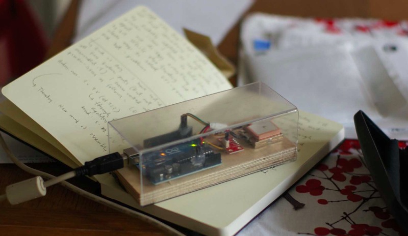
This is a GPS receiver connected to Arduino that sends data to a piece of software running on a laptop. It is a quickly designed tool, a transparent plastic box that that allows us to observe the performance of the electronics, and still mobile enough to carry in hand or a backpack.

Arduino Blog 09 Oct 17:42
arduino  arduino uno  featured  gps  lamp  lamp(s)  oslo  

Tinkernut’s Lamp Comes To Life Using Ultrasonic Waves

The Motion Controlled Ultrasonic Lamp is great for beginners starting out with the Arduino Uno. It may or may not detect ninjas but will illuminate and follow most everyone else.

Read more on MAKE

MAKE » Arduino 03 Oct 17:01

Lamp Comes to Life with Ultrasonic Sensors

Fans of the bouncing lamp from the Pixar corporate logo will enjoy [Daniel]‘s latest project. It’s a motion controlled desk lamp that uses ultrasonic sensors to control its physical position.

The core of the project is an Arduino and the three ultrasonic sensors. The sensors act as range finders, and when they are all working together under the direction of the microcontroller they can tell which direction a hand was moving when it passed by. This information is used to drive two servos, one in the base and one on the lamp’s arm.

The project requires an articulating desk lamp of some sort (others besides the specific one [Daniel] used shouldn’t be much of a problem as long as they bend in the same way). Most hackers will have the rest of the parts on hand, with the possible exception of the rangefinder. The code is up on the project site for a look-see or in case you want to build your own.

The only problem that [Daniel] had when putting this all together was that the base was a little wobbly. He was able to fix that with some thumbtacks, and we think the next step for the project should be switching the light on and off over the internet.


Filed under: home hacks