

New dimmer software
Based on the success of the stroboscope software, I rewrote the dimmer software for my desk lamp (see LED lamp projects for more about the lamps). The new software provides smoother control of the light levels (having 256 levels plus off, rather than 63 levels plus off) and now has a 256:1 brightness range rather than the approximately 256:6 range of the previous code.
I removed a lot of the general-purpose crap that was inherited from core13 (which was in turn stripped down from the Arduino core software). I did not get rid of all of core13, so I could probably take out another 50–100 bytes, but the code is down to 222 bytes (and the ATtiny13A has 1kB of flash, so I’m way below the limit).
The actual brightness range of the new dimmer is a bit more than 256:1, because on the shortest pulse the FET doesn’t turn all the way on. The pulse duration from the ATtiny13A is approximately 3.4µs times the brightness level (9.6MHz clock divided down by 4 and by 8), but I had deliberately slowed the FET transitions by adding a series resistor to the gate, so that nFET doesn’t finish turning on for 5.2µs (as judged by the end of the Miller plateau on the gate). So at the lowest brightness level, the nFET does not turn all the way on and the voltage on the drain only gets down to 3.5V, which leaves 5.5V across the LED board—enough to turn on the LED, but with only about 10mA, not 118mA. At this low level, the LEDs sometimes flicker, perhaps as a result of some thermal feedback effects. The all flicker together, so the effect is probably in the dimmer’s nFET, not on the LED boards.
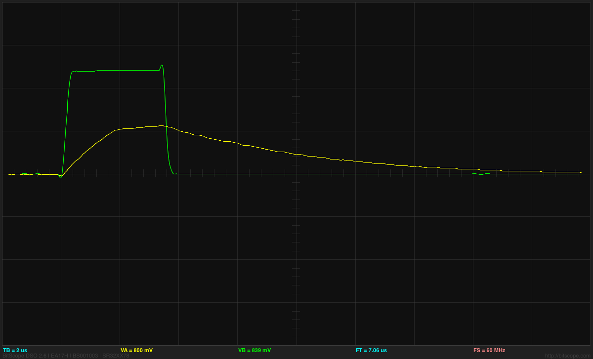
ATtiny output (green) and gate voltage (yellow) at 2V/division and 2µs/division for the shortest pulse length. The gate voltage has not quite reached the end of the Miller plateau before being discharged again.
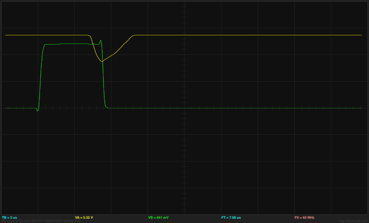
ATtiny output (green) and drain voltage (yellow) at 2V/division and 2µs/division for the shortest pulse length. The BitScope BS-10 oscilloscope clips the voltage to 5.5V—it actually goes to 9V.
At the next brightness level, the drain voltage does drop to 0V for at least 2.4µs and stays low enough for the LED board to be at maximum current (below 2.5V) for at least 5.5µs. There is an enormous difference in brightness between length 2 and length 1 pulses (more like 1:20 than 1:2), because of the low current for pulse length 1, but for length 2 and longer the steps in brightness are pretty much as one would expect from the pulse lengths.
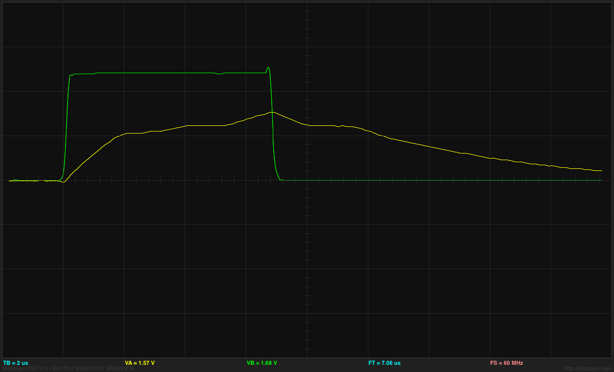
ATtiny output (green) and gate voltage (yellow) at 2V/division and 2µs/division for the shortest pulse length. The gate voltage has gone past the end of the Miller plateau and started charging past that point. The Miller plateau is also visible on the discharge as the nFET turns off.
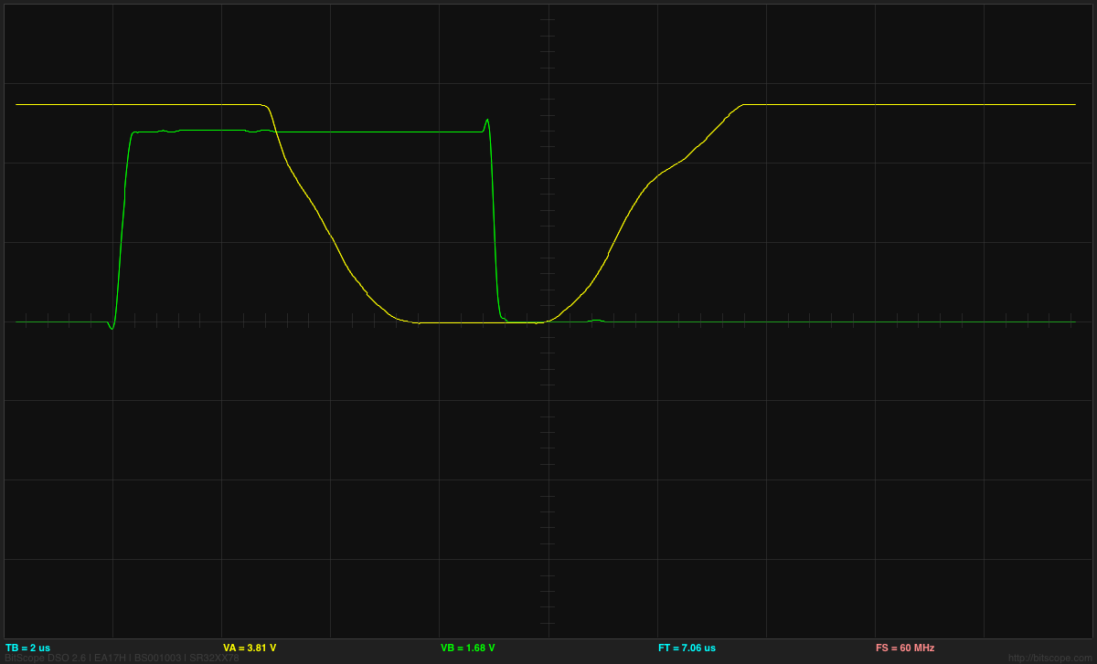
ATtiny output (green) and drain voltage (yellow) at 2V/division and 2µs/division for the second shortest pulse length. The BitScope BS-10 oscilloscope clips the voltage to 5.5V—it actually goes to 9V.
The longer pulses allow the nFET to turn on fully.
The conversion from the linear 10-bit analog-to-digital reading (0–1023) to pulse lengths is done by the following method:
expon = ADC>>7
frac = 0x80 + (ADC & 0x7f)
pulse_len = ADC < 0x20? 0:  ADC < 0x40? 1: 1+ (frac>> (7-expon))
The stepwise nature of the brightness at low levels is apparent in a plot of the conversion function:

The steps in brightness are quite visible at the low end, but after the first 10 steps, the differences are small enough not to be easily noticed.
Overall, I’m pleased with the rework of the dimmer code. I’ll probably have to solder up another of the dimmer boards this summer, since I’ll want one for the light fixture that I haven’t started building yet and one for the Halloween stroboscope.
Filed under: Uncategorized Tagged: Arduino, ATtiny, BitScope, dimmable LED lamps, lamp, Miller plateau


