Our weather station LIVE
There are several softwares that enable the publication of the weather data of a professional weather station, but they all work on PC, so we should connect the weather station to a computer and leave it on, the idea is not good because the computer takes up space and consumes a lot. At a time when we should spare the energy, its not a good thing.
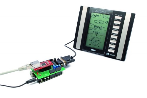
The project we’re talking about instead operates as a stand-alone application and allows you to publish the weather station data independently on http://www.wunderground.com, “forgetting” the PC consumption and even the desk space.
Arduino controls the dialogue with the weather station to acquire the data and also the Ethernet interface to transfer them, by making the necessary connection to the Internet via ADSL, passing by a router pointing to the IP address of the Weather Underground site and transferring information using the TCP / IP.
Our project
This circuit reads data from a weather station with serial interface and upload the data collected on http://www.wunderground.com.
Not all stations are equal, therefore, our circuit can not be universal but it is indicated specifically for stations La Crosse WS2355, WS2300 or WS2350.

The choice of weather station WS23xx was dictated primarily by a consideration: it has a convenient serial interface to connect and dialogue with a microcontroller such as Arduino.
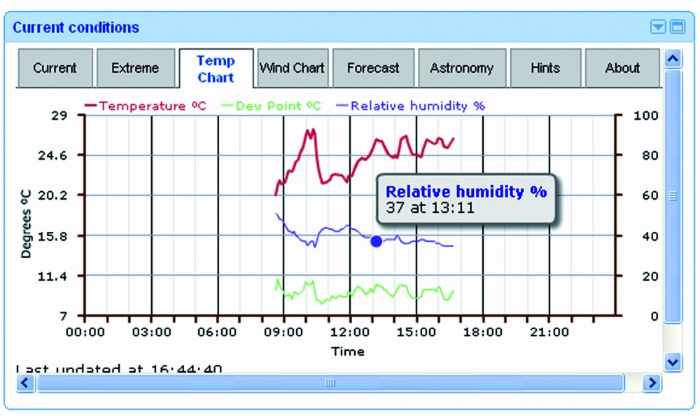
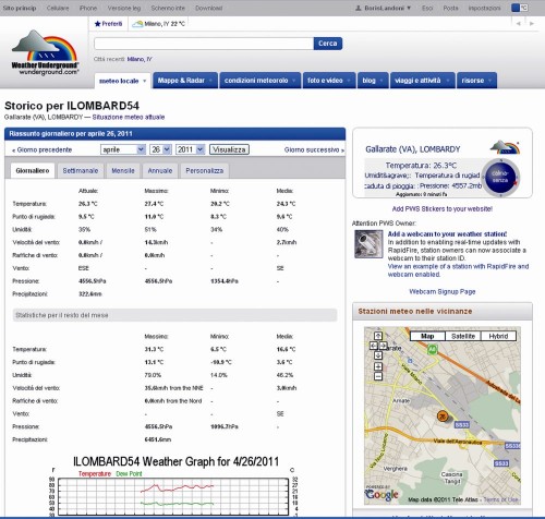
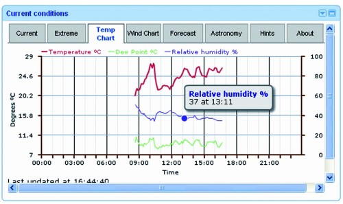
We chose www.wunderground.com site because it allows anyone to upload their weather data, but also to monitor the temperature, humidity, pressure, wind etc. on line. Also on this site there are many widgets that allow you to integrate data in website or blog.
An example is the Widget for the home page of Google.
The data sent by users are publicly available, then from the home page we can specify the geographic area that interests us and we will see a screen that lists all of the corresponding stations.
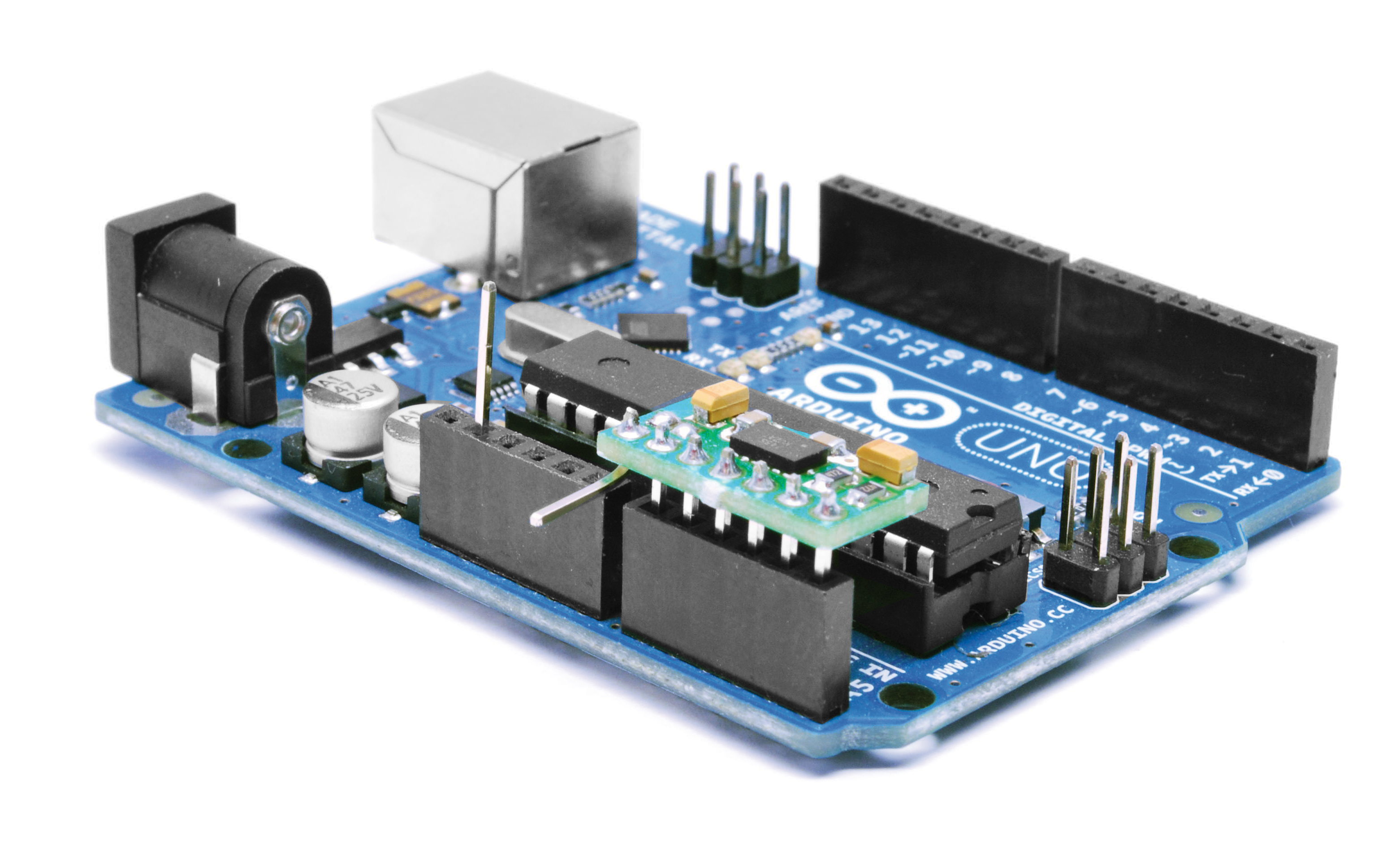
How does it work?
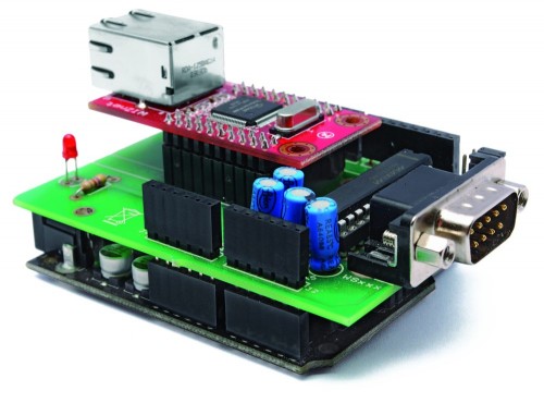
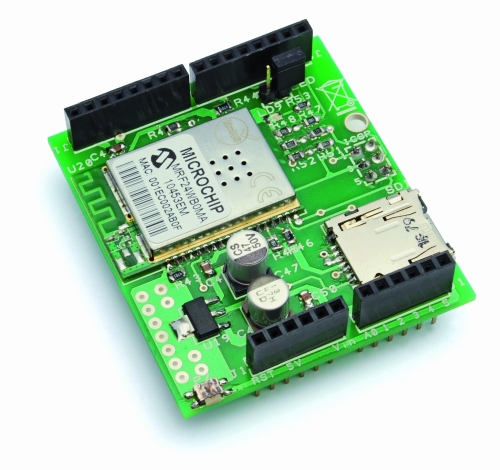
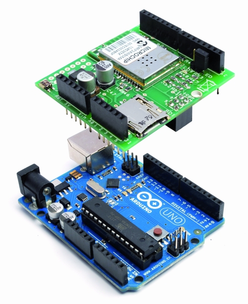
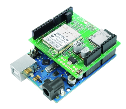
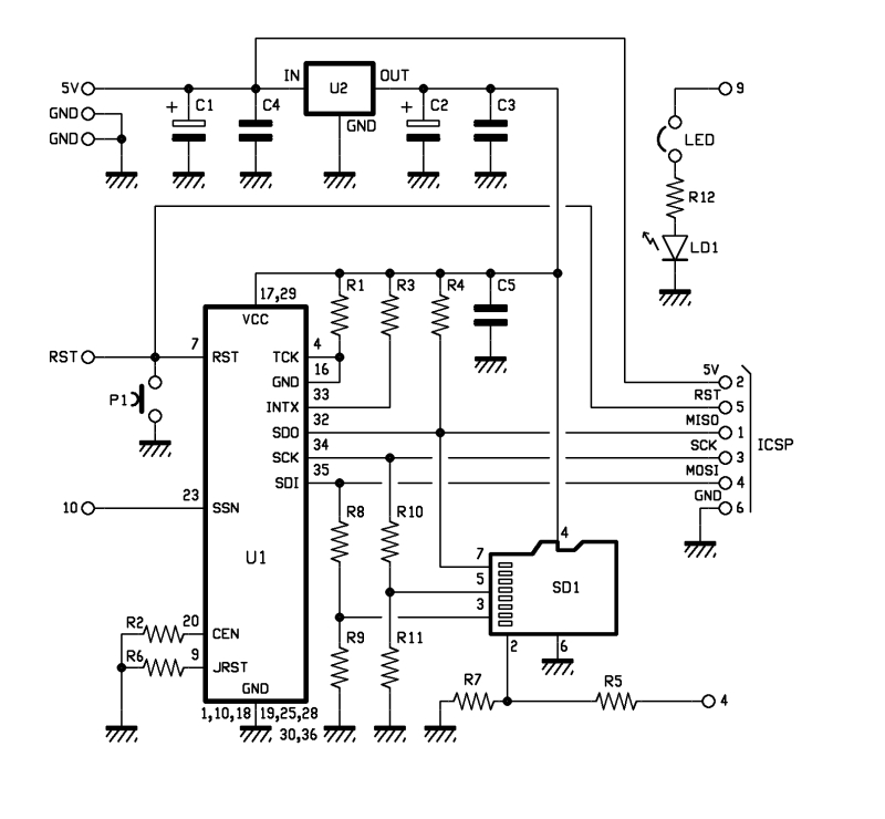
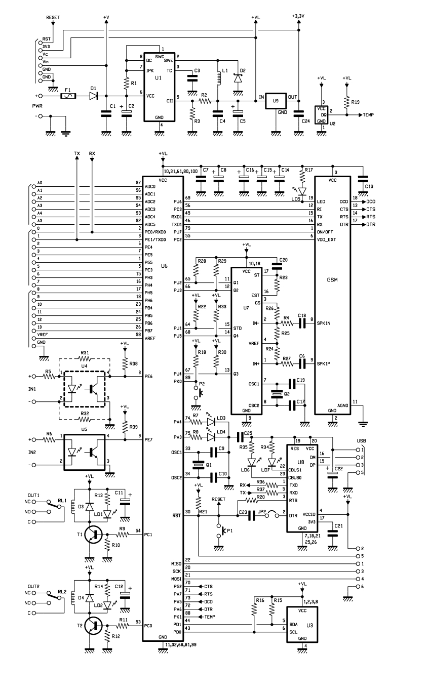
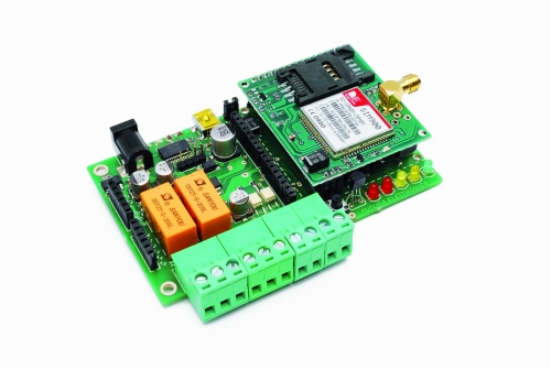
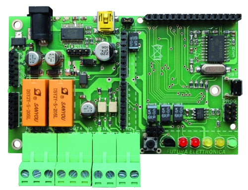
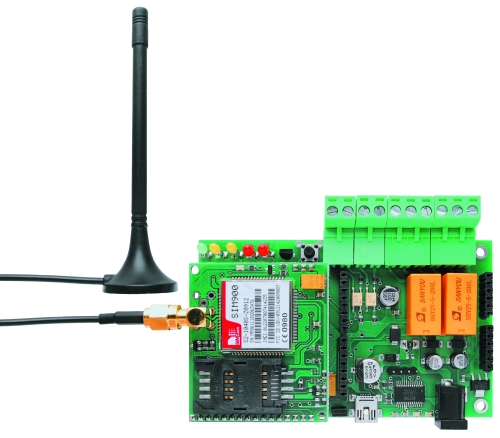
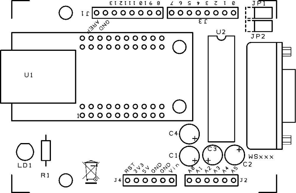
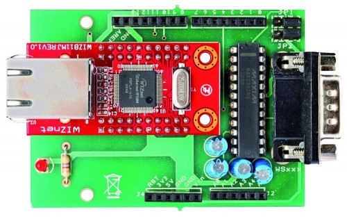
The system has two circuit: one is the famous Arduino UNO and the other is a shield that integrates the Ethernet module WIZnet (you may, of course, use the the original Ethernet Shield), as well as a TTL/RS232 logic level converter MAX238 type. The converter allows you to adapt the serial levels of weather station to the TTL levels of Arduino.
Please be aware that the communication port of the weather station is not a simple RS232, because it has no ground reference. The DTR line must have a negative voltage while the RTS must be positive. The lack of common ground leads to the hypothesis (remember that there is no official document) that these two lines are taken as a reference of logic levels used in communication. It is a system that not only allows the use of serial connections relatively long, but also gives the opportunity to agree devices with different voltage levels on the serial port.
To communicate with La Crosse, the speed of the serial device (in our case, the Arduino module) must be set to 2,400 bps, with blocks of 8 bits, no parity and one stop bit (2400-8-N-1).
The memory map of the weather station, like many other unofficial information on the WS2355 is on the site http://www.lavrsen.dk/foswiki/bin/view/Open2300/WebHome.
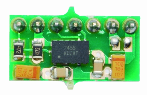
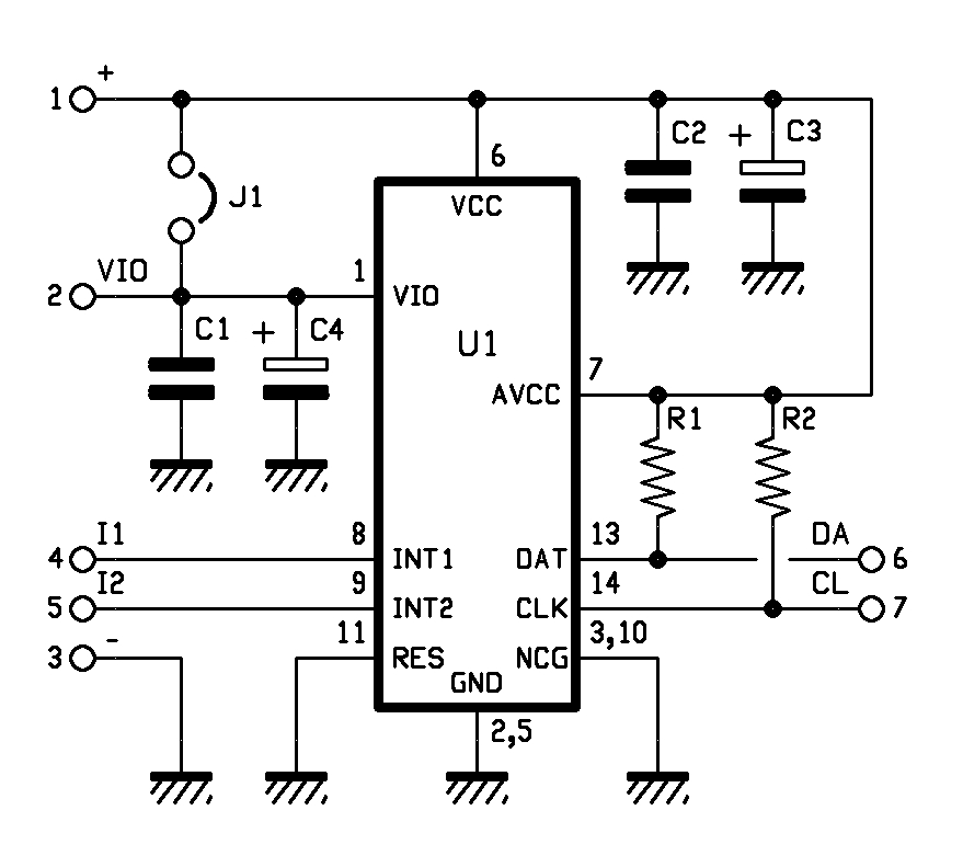
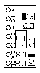
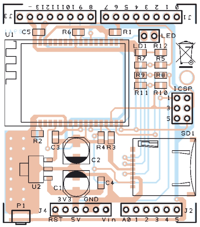
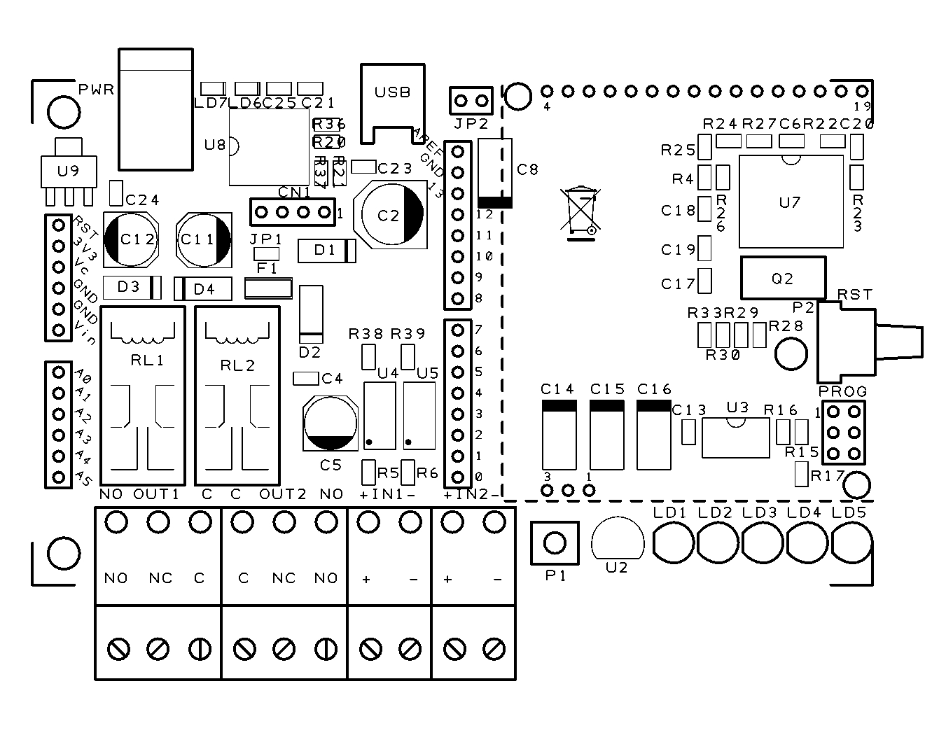
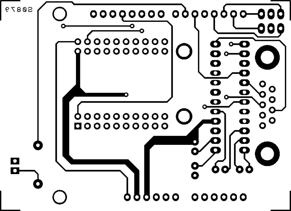
The hardware
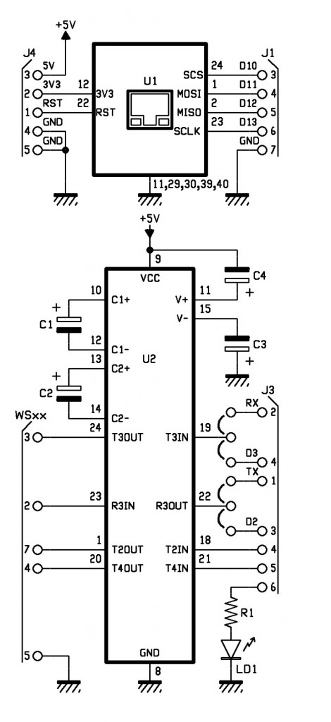
The jumpers on the lines T3IN and R3OUT (respectively RS232/TTL converter output and RS232/TTL converter input) let you choose which lines use for Arduino communication: we give you the opportunity to choose if use the serial hardware TXD and RXD or the two I/O digital D2 and D3 emulating a serial port with the appropriate library that can be downloaded from the website http://arduiniana.org/libraries/newsoftserial.
R1: 470 ohm
C1: 1 µF 100 VL
C2: 1 µF 100 VL
C3: 1 µF 100 VL
C4: 1 µF 100 VL
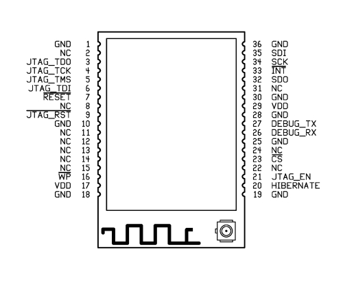
U1: WIZNET
U2: MAX238CNG
LD1: led 3 mm red
- socket 12+12
- Strip male 3 via (2 pz.)
- Jumper (2 pz.)
- Strip female/male 6 via (2 pz.)
- Strip female/male 8 via(2 pz.)
- Strip female 10 via (4 pz.)
- DB9 male
- PCB
The sketch
/*
****************************************************************
* Name : Personal Weather Station to wunderground.com *
* Author : Landoni Boris *
* www.open-electronics.org *
* blog.elettronicain.it *
* www.futurashop.it *
****************************************************************
http://wiki.wunderground.com/index.php/PWS_-_Upload_Protocol#Example_URL
action [action=updateraw] -- always supply this parameter to indicate you are making a weather observation upload
ID [ID as registered by wunderground.com]
PASSWORD [PASSWORD registered with this ID, case sensative]
dateutc - [YYYY-MM-DD HH:MM:SS (mysql format)] In Universal Coordinated Time (UTC) Not local time
winddir - [0-360 instantaneous wind direction]
windspeedmph - [mph instantaneous wind speed]
humidity - [% outdoor humidity 0-100%]
tempf - [F outdoor temperature]
rainin - [rain inches over the past hour)] -- the accumulated rainfall in the past 60 min
indoortempf - [F indoor temperature F]
indoorhumidity - [% indoor humidity 0-100]
softwaretype - [text] ie: WeatherLink, VWS, WeatherDisplay
windgustmph - [mph current wind gust, using software specific time period]
windgustdir - [0-360 using software specific time period]
windspdmph_avg2m - [mph 2 minute average wind speed mph]
winddir_avg2m - [0-360 2 minute average wind direction]
windgustmph_10m - [mph past 10 minutes wind gust mph ]
dewptf- [F outdoor dewpoint F]
dailyrainin - [rain inches so far today in local time]
baromin - [barometric pressure inches]
weather - [text] -- metar style (+RA)
clouds - [text] -- SKC, FEW, SCT, BKN, OVC
soiltempf - [F soil temperature]
* for sensors 2,3,4 use soiltemp2f, soiltemp3f, and soiltemp4f
soilmoisture - [%]
* for sensors 2,3,4 use soilmoisture2, soilmoisture3, and soilmoisture4
leafwetness - [%]
+ for sensor 2 use leafwetness2
solarradiation - [W/m^2]
UV - [index]
visibility - [nm visibility]
http://weatherstation.wunderground.com/weatherstation/updateweatherstation.php?ID=KCASANFR5&PASSWORD=XXXXXX&dateutc=2000-01-01+10%3A32%3A35&winddir=230&windspeedmph=12&windgustmph=12&tempf=70&rainin=0&baromin=29.1&dewptf=68.2&humidity=90&weather=&clouds=&softwaretype=vws%20versionxx&action=updateraw
mappa ws2300
Command Hex Digit Command Hex Digit
82 0 A2 8
86 1 A6 9
8A 2 AA A
8E 3 AE B
92 4 B2 C
96 5 B6 D
9A 6 BA E
9E 7 BE F
*/
#include <SPI.h>
#include <Ethernet.h>
#include <EEPROM.h>
#include <NewSoftSerial.h>
byte mac[] = { 0xDE, 0xAD, 0xBE, 0xEF, 0xFE, 0xED };
byte ip[] = { 192,168,0,145 };
byte server[] = { 38,102,136,125 }; // http://weatherstation.wunderground.com/
#define UPDATE_INTERVAL 300000 // if the connection is good wait 60 seconds before updating again - should not be less than 5
unsigned long update=0;
NewSoftSerial mySerial(2, 3); //NewSoftSerial mySerial(rx,tx);
const int ledPin = 6; // the pin that the LED is attached to
const int rts = 4;
const int dtr = 5;
String id = "xxxxxxx";
String PASSWORD = "xxxxxxx";
boolean upload=1;
boolean leggicontinuo=0;
Client client(server, 80);
void setup() {
Ethernet.begin(mac, ip);
digitalWrite(ledPin, LOW);
// initialize serial communication:
Serial.begin(2400);
Serial.println("Goodmorning WS2300!");
// set the data rate for the NewSoftSerial port
mySerial.begin(2400);
// initialize the LED pin as an output:
pinMode(ledPin, OUTPUT);
pinMode(rts, OUTPUT);
pinMode(dtr, OUTPUT);
digitalWrite(rts, HIGH);
digitalWrite(dtr, LOW);
delay(2000);
digitalWrite(rts, LOW);
digitalWrite(dtr, HIGH);
for (int i=0;i<10;i++){
digitalWrite(ledPin, HIGH);
delay(200);
digitalWrite(ledPin, LOW);
delay(200);
}
}
void loop() {
int incomingByteSer; // a variable to read incoming serial data into
// see if there's incoming serial data:
if (Serial.available() > 0) {
// read the oldest byte in the serial buffer:
incomingByteSer = Serial.read();
// if it's a capital H (ASCII 72), turn on the LED:
Serial.flush();
if (incomingByteSer == 'o') {
String data=getTime();
Serial.print("ora ");
Serial.println(data);
}
if (incomingByteSer == 'd') {
String data=getDay();
Serial.print("giorno ");
Serial.println(data);
}
if (incomingByteSer == 't') {
String data=getTemp(1);
Serial.print("temperatura interna F ");
Serial.println(data);
}
if (incomingByteSer == 'T') {
String data=getTemp(0);
Serial.print("temperatura esterna F ");
Serial.println(data);
}
if (incomingByteSer == 'h') {
String data=getHum(1);
Serial.print("umidità interna ");
Serial.println(data);
}
if (incomingByteSer == 'H') {
String data=getHum(0);
Serial.print("umidità esterna ");
Serial.println(data);
}
if (incomingByteSer == 'p') {
String data=getPress(1);
Serial.print("pressione hPa ");
Serial.println(data);
}
if (incomingByteSer == 'P') {
String data=getPress(0);
Serial.print("pressione Hg ");
Serial.println(data);
}
if (incomingByteSer == 'w') {
String data=getWind(0);
Serial.print("wind speed mph ");
Serial.println(data);
}
if (incomingByteSer == 'W') {
String data=getWind(1);
Serial.print("wind dir ");
Serial.println(data);
}
if (incomingByteSer == 'r') {
String data=getRain(1);
Serial.print("rain 1 ");
Serial.println(data);
}
if (incomingByteSer == 'R') {
String data=getRain(0);
Serial.print("rain 24 ");
Serial.println(data);
}
if (incomingByteSer == 'e') {
String data=getDew();
Serial.print("dew point ");
Serial.println(data);
}
if (incomingByteSer == 'U') {
readws();
}
if (incomingByteSer == 'u') {
pubblica();
}
if (incomingByteSer == 'a') {
if (upload==1){
upload=0;
Serial.println("Disattivo l'upload automatico ");
}
else
{
upload=1;
Serial.println("Attivo l'upload automatico ");
}
}
if (incomingByteSer == 'A') {
if (leggicontinuo==1){
leggicontinuo=0;
Serial.println("Disattivo lettura continua ");
}
else
{
leggicontinuo=1;
Serial.println("Attivo lettura continua ");
}
}
// if it's an L (ASCII 76) turn off the LED:
if (incomingByteSer == 'L') {
digitalWrite(ledPin, LOW);
}
}
if (upload==1){
if (millis() < update) update = millis();
if ((millis()% 1000) < 2){
delay (100);
Serial.print(".");
}
if ((millis() - update) > UPDATE_INTERVAL){
update = millis();
readws();
pubblica();
Serial.println("tempo impiegato per fare la pubblicazione: ");
Serial.println(millis()-update);
}
}
if (leggicontinuo==1){
if (millis() < update) update = millis();
if ((millis()% 1000) < 2){
delay (100);
Serial.print(".");
}
if ((millis() - update) > UPDATE_INTERVAL){
update = millis();
readws();
}
}
}
void pubblica()
{
int timeout=0;
int skip=0;
String inString="";
digitalWrite(ledPin, HIGH);
Serial.print("connecting ");
if (client.connect()) {
Serial.println("connected");
//client.println("GET / HTTP/1.0");
Serial.print("GET /weatherstation/updateweatherstation.php?");//modificare qua.
client.print("GET /weatherstation/updateweatherstation.php?");//modificare qua.
pubbws();
client.println(" HTTP/1.0");
Serial.println(" HTTP/1.0");
Serial.print("HOST: ");
client.print("HOST: ");
client.println("http://www.wunderground.com");
Serial.println("http://www.wunderground.com");
client.println();
} else {
Serial.println("connection failed");
}
while (!client.available() && timeout<50)
{
timeout++;
Serial.print("Time out ");
Serial.println(timeout);
delay(100);
}
while (client.available())
{
char c = client.read();
if ((inString.length())<150){ inString.concat(c);}
}
client.flush();
if ((inString.length())>5)
{
Serial.print("Risposta ");
Serial.print(inString);
}
if (!client.connected())
{
Serial.println("disconnecting.");
client.stop();
delay (1000);
}
digitalWrite(ledPin, LOW);
}
void readws(){
Serial.println("URL ");
Serial.print("http://weatherstation.wunderground.com/weatherstation/updateweatherstation.php?");
String temp =getDay();
String temp1=getTime();
if ((temp.length()>6) && (temp1.length()>4)){
Serial.print("ID=");
Serial.print(id);
Serial.print("&PASSWORD=");
Serial.print(PASSWORD);
Serial.print("&dateutc=");
Serial.print(temp);
Serial.print("+");
Serial.print(temp1);
scrivimem(temp,0);
scrivimem(temp1,20);
}
else
{
Serial.println("Lettura data/ora non riuscita torno");
return;
}
temp=getWind(1);
if (temp.length()>1){
Serial.print("&winddir=");
Serial.print(temp);
scrivimem(temp,40);
}
temp=getWind(0);
if (temp.length()>2){
Serial.print("&windspeedmph=");
Serial.print(temp);
scrivimem(temp,60);
}
temp=getTemp(0);
if (temp.length()>3){
Serial.print("&tempf=");
Serial.print(temp);
scrivimem(temp,80);
}
temp=getRain(1);
if (temp.length()>2){
Serial.print("&rainin=");
Serial.print(temp);
scrivimem(temp,100);
}
temp=getRain(0);
if (temp.length()>2){
Serial.print("&dailyrainin=");
Serial.print(temp);
scrivimem(temp,120);
}
temp=getHum(0);
if (temp.length()>1){
Serial.print("&humidity=");
Serial.print(temp);
scrivimem(temp,140);
}
temp=getDew();
if (temp.length()>1){
Serial.print("&dewptf=");
Serial.print(temp);
scrivimem(temp,160);
}
temp=getPress(0);
if (temp.length()>1){
Serial.print("&baromin=");
Serial.print(temp);
scrivimem(temp,180);
}
}
void pubbws(){
String temp =leggimem(0);
String temp1=leggimem(20);
if ((temp.length()>6) && (temp1.length()>4)){
Serial.print("ID=");
Serial.print(id);
Serial.print("&PASSWORD=");
Serial.print(PASSWORD);
Serial.print("&dateutc=");
Serial.print(temp);
Serial.print("+");
Serial.print(temp1);
client.print("ID=");
client.print(id);
client.print("&PASSWORD=");
client.print(PASSWORD);
client.print("&dateutc=");
client.print(temp);
client.print("+");
client.print(temp1);
}
else
{
Serial.println("Lettura data/ora non riuscita torno");
return;
}
temp=leggimem(40);
if (temp.length()>1){
Serial.print("&winddir=");
Serial.print(temp);
client.print("&winddir=");
client.print(temp);
}
temp=leggimem(60);
if (temp.length()>2){
Serial.print("&windspeedmph=");
Serial.print(temp);
client.print("&windspeedmph=");
client.print(temp);
}
temp=leggimem(80);
if (temp.length()>3){
Serial.print("&tempf=");
Serial.print(temp);
client.print("&tempf=");
client.print(temp);
}
temp=leggimem(100);
if (temp.length()>2){
Serial.print("&rainin=");
Serial.print(temp);
client.print("&rainin=");
client.print(temp);
}
temp=leggimem(120);
if (temp.length()>2){
Serial.print("&dailyrainin=");
Serial.print(temp);
client.print("&dailyrainin=");
client.print(temp);
}
temp=leggimem(140);
if (temp.length()>1){
Serial.print("&humidity=");
Serial.print(temp);
client.print("&humidity=");
client.print(temp);
}
temp=leggimem(160);
if (temp.length()>1){
Serial.print("&dewptf=");
Serial.print(temp);
client.print("&dewptf=");
client.print(temp);
}
temp=leggimem(180);
if (temp.length()>1){
Serial.print("&baromin=");
Serial.print(temp);
client.print("&baromin=");
client.print(temp);
}
Serial.print("&windgustmph=0.00");
client.print("&windgustmph=0.00");
Serial.print("&action=updateraw");
client.print("&action=updateraw");
}
void scrivimem(String dataStr, int pos){
for (int i=0; i<dataStr.length();i++)
{
EEPROM.write((pos+i),dataStr[i]);
}
EEPROM.write((pos+dataStr.length()),'#');
for (int i=pos;i<(pos+50);i++)
{
if (EEPROM.read(i)=='#')
{
break;
}
}
}
String leggimem(int pos){
int lung=0;
char dataStr[15];
for (int i=0;i<15;i++)
{
dataStr[i]=0;
}
for (int i=pos;i<(pos+20);i++)
{
lung++;
if (EEPROM.read(i)=='#')
{
break;
}
char c=EEPROM.read(i);
dataStr[i-pos]=(c);
}
dataStr[lung]='\0';
return(dataStr);
}
String Leggi (int mem[]) {
String inString;
char inChar [3];
int incomingByte=0; // a variable to read incoming serial data into
int time=0;
String chk;
while ((incomingByte!=2) && (time<20)){
time++;
mySerial.print(byte(06));
delay(20);
if ((mySerial.available() > 0) && (time<20)) {
delay(30);
time++;
incomingByte = mySerial.read();
inString.concat(incomingByte);
}
}
inString="";
time=0;
inString.concat("00"); //aggiungo due cifre
mySerial.flush();
if (time>18){
return("0\0");
}
for (int i=0; i<2; i++){
if (inString.length()>8){
chk=(inString.substring(4,8));
}
inString="";
inString.concat("00"); //aggiungo due cifre
for (int tmp=0; tmp<5; tmp++){
mySerial.print(byte(mem[tmp]));
while ((mySerial.available() == 0) && (time<100)){
delay(30);
time++;
}
if (time>98){
return("0\0");
break;
}
if (mySerial.available() > 0) {
incomingByte = mySerial.read();
}
time=0;
//delay(200);
while ((mySerial.available() > 0) && time<200 ) {
time++;
delay(20);
incomingByte = mySerial.read();
if (tmp<4){
if (tmp!=((incomingByte & B11110000)/B10000)){
return("0\0");
break;
}
}
if (tmp==4){
sprintf(inChar, "%02X", incomingByte);
inString.concat(inChar);
}
}
}
}
if (chk!=(inString.substring(4,8)))
{
return("0\0");
}
inString=inString.trim();
if (inString.length()>16){
inString=(inString.substring(0,15));
}
return(inString);
}
String getTime(){
String dataStr="";
int my_array[] = {0x82,0x8A,0x82,0x82,0xDA}; //0200
String inString;
for (int ritenta=0; ritenta<10; ritenta++){
dataStr="";
inString=Leggi(my_array);
if (inString.length()>5){
//data= inString.substring(4,6); //estraggo i decimali della temperatura
dataStr.concat(inString.substring(6,8)); //estraggo l'ora
dataStr.concat(":");
dataStr.concat(inString.substring(4,6)); //estraggo i minuti
dataStr.concat(":");
dataStr.concat(inString.substring(2,4)); //estraggo i secondi
if (((inString.substring(6,8))<23 && (inString.substring(6,8))>=0)&&((inString.substring(4,6))<60 && (inString.substring(4,6))>=0) && ((inString.substring(2,4))<60 && (inString.substring(2,4))>=0)) {
break;
}
else {
dataStr="";
}
}
else
{
delay(500);
}
}
return(dataStr);
}
String getDay(){
String inString;
String dataStr="";
int my_array[] = {0x82,0x8A,0x8E,0xAE,0xEE};
for (int ritenta=0; ritenta<10; ritenta++){
dataStr="";
inString=Leggi(my_array);
if (inString.length()>5){
dataStr.concat("20");
dataStr.concat(inString.charAt(13));
dataStr.concat(inString.charAt(10));
dataStr.concat("-");
dataStr.concat(inString.charAt(11));
dataStr.concat(inString.charAt(8));
dataStr.concat("-");
dataStr.concat(inString.charAt(9));
dataStr.concat(inString.charAt(6));
if (((inString[13]<='9' && inString[13]>='0')&&(inString[10]<='9' && inString[10]>='0')) && ((inString[11]<='1' && inString[11]>='0')&&(inString[8]<='9' && inString[8]>='0')) && ((inString[9]<='3' && inString[9]>='0')&&(inString[6]<='9' && inString[6]>='0'))) {
break;
}
else {
dataStr="";
}
}
else
{
delay(500);
}
}
return(dataStr);
}
String getTemp(int dato){
String inString;
String dataStr="";
//String dataStr;
char cdata [10];
int lung=0;
char buff[10];
int my_array[6];
if (dato==1){
my_array[0] = (0x82);
my_array[1] = (0x8E);
my_array[2] = (0x92);
my_array[3] = (0x9A);
my_array[4] = (0xFA);
}
else
{
my_array[0] = (0x82);
my_array[1] = (0x8E);
my_array[2] = (0x9E);
my_array[3] = (0x8E);
my_array[4] = (0xFA);
}
for (int ritenta=0; ritenta<10; ritenta++){
dataStr="";
inString=Leggi(my_array);
if (inString.length()>5){
(inString.substring(4,6)).toCharArray(buff,3);
dataStr.concat((atoi(buff))-30);
dataStr.concat(".");
dataStr.concat(inString.substring(2,4)); //estraggo le decine e unità della temperatura
if (((inString[4]<='9' && inString[4]>='0')&&(inString[5]<='9' && inString[5]>='0')) && ((inString[2]<='9' && inString[2]>='0')&&(inString[3]<='9' && inString[3]>='0'))) {
break;
}
else {
dataStr="";
}
}
else
{
delay(500);
}
}
if (dataStr.length()>2)
{
dataStr.toCharArray(cdata, dataStr.length()+1);
float fdata=(atof(cdata)*1.800+32.000);
if (fdata<1000){lung=7;}
if (fdata<100){lung=6;}
if (fdata<10){lung=5;}
dtostrf(fdata,lung,3,cdata);
dataStr=cdata;
}
else
{
dataStr="";
}
return(dataStr);
}
String getHum(int dato){
String dataStr="";
String inString;
int my_array[6];
if (dato==1){
my_array[0] = (0x82);
my_array[1] = (0x8E);
my_array[2] = (0xBE);
my_array[3] = (0xAE);
my_array[4] = (0xDA);
}
else
{
my_array[0] = (0x82);
my_array[1] = (0x92);
my_array[2] = (0x86);
my_array[3] = (0xA6);
my_array[4] = (0xDA);
}
for (int ritenta=0; ritenta<10; ritenta++){
dataStr="";
inString=Leggi(my_array);
if (inString.length()>5){
dataStr.concat(inString.substring(2,4)); //estraggo le decine e unità della temperatura
if ((inString[2]<='9' && inString[2]>='0')&&(inString[3]<='9' && inString[3]>='0')) {
break;
}
else {
dataStr="";
}
}
else
{
delay(500);
}
}
return(dataStr);
}
String getPress(int dato){
String dataStr="";
String inString;
int my_array[6];
if (dato==1){
my_array[0] = (0x82);
my_array[1] = (0x96);
my_array[2] = (0xBA);
my_array[3] = (0x8A);
my_array[4] = (0xD6);
}
else
{
my_array[0] = (0x82); //press hg
my_array[1] = (0x96);
my_array[2] = (0xB6);
my_array[3] = (0xB6);
my_array[4] = (0xD6);
}
for (int ritenta=0; ritenta<10; ritenta++){
dataStr="";
inString=Leggi(my_array);
if (inString.length()>5){
dataStr.concat(inString.charAt(7));
dataStr.concat(inString.charAt(4));
dataStr.concat(inString.charAt(5));
if (dato==1){
dataStr.concat(inString.charAt(2));
dataStr.concat(".");
dataStr.concat(inString.charAt(3));
}
else
{
dataStr.concat(".");
dataStr.concat(inString.charAt(2));
dataStr.concat(inString.charAt(3));
}
if ((inString[7]<='9' && inString[7]>='0')&&(inString[4]<='9' && inString[4]>='0') && (inString[5]<='9' && inString[5]>='0')&&(inString[2]<='9' && inString[2]>='0') && (inString[2]<='9' && inString[2]>='0')) {
break;
}
else {
dataStr="";
}
}
else
{
delay(500);
}
}
return(dataStr);
}
String getWind(int dato){
String dataStr="";
char cdata [10];
int lung=0;
String inString;
char buff[10];
int my_array[] = {0x82,0x96,0x8A,0x9E,0xF2};
for (int ritenta=0; ritenta<10; ritenta++){
dataStr="";
inString=Leggi(my_array);
if (inString.length()>5){
if (dato==0){
dataStr.concat(inString.charAt(7));
buff[0]=inString[4];
buff[1]=inString[5];
int tmp=(strtol(buff,NULL,16));
if (tmp<=9){
dataStr.concat("0");
}
dataStr.concat(tmp); // converts a HEX string to long
dataStr.concat(dataStr.charAt(2));
dataStr.setCharAt(2, '.');
if ((inString[4]<='9' && inString[4]>='0')&&(inString[5]<='9' && inString[5]>='0')) {
break;
}
else {
dataStr="";
}
}
else
{
buff[0]=inString[6];
buff[1]=0;
int tmp=((strtol(buff,NULL,16))*22.5);
dataStr.concat(tmp);
if ((tmp>=0)&&(tmp<=360)) {
break;
}
else {
dataStr="";
ritenta=0;
}
}
}
else
{
delay(500);
}
}
if (dato==0){ //se richiedo la velocità convertoin miglia orarie
if (dataStr.length()>2)
{
dataStr.toCharArray(cdata, (dataStr.length()+1));
float fdata=(atof(cdata)*2.23);
if (fdata<1000){lung=6;}
if (fdata<100){lung=5;}
if (fdata<10){lung=4;}
dtostrf(fdata,lung,2,cdata);
dataStr=cdata;
}
else
{
dataStr="";
}
}
return(dataStr);
}
String getRain(int dato){
String dataStr="";
char cdata [10];
int lung=0;
String inString;
int my_array[6];
if (dato==1){ //pioggia 1 ora
my_array[0] = (0x82);
my_array[1] = (0x92);
my_array[2] = (0xAE);
my_array[3] = (0x92);
my_array[4] = (0xDA);
}
else
{
my_array[0] = (0x82); //0497
my_array[1] = (0x96);
my_array[2] = (0xA6);
my_array[3] = (0x9E);
my_array[4] = (0xD6);
}
for (int ritenta=0; ritenta<10; ritenta++){
dataStr="";
inString=Leggi(my_array);
if (inString.length()>5){
dataStr.concat(inString.substring(6,8));
dataStr.concat(inString.substring(4,6));
if ((inString[6]<='9' && inString[6]>='0')&&(inString[7]<='9' && inString[7]>='0') && (inString[4]<='9' && inString[4]>='0')&&(inString[5]<='9' && inString[5]>='0') && (inString[2]<='9' && inString[2]>='0')&& (inString[3]<='9' && inString[3]>='0')) {
break;
}
else {
dataStr="";
}
}
else
{
delay(500);
}
}
if (dataStr.length()>2)
{
dataStr.toCharArray(cdata, (dataStr.length()+1));
//Serial.print("cdata ");
//Serial.println(cdata);
float fdata=(atof(cdata)*2.54); //in pollici
if (fdata<1000){lung=6;}
if (fdata<100){lung=5;}
if (fdata<10){lung=4;}
dtostrf(fdata,lung,2,cdata);
dataStr=cdata;
}
else
{
dataStr="";
}
return(dataStr);
}
String getDew(){
String inString;
String dataStr="";
char cdata [10];
int lung=0;
char buff[10];
//Serial.println("leggo pioggia 1h ");
int my_array[] = {0x82,0x8E,0xB2,0xBA,0xFA};
for (int ritenta=0; ritenta<10; ritenta++){
dataStr="";
inString=Leggi(my_array);
if (inString.length()>5){
(inString.substring(4,6)).toCharArray(buff,3);
dataStr.concat((atoi(buff))-30);
dataStr.concat(".");
dataStr.concat(inString.substring(2,4)); //estraggo le decine e unità della temperatura
if (((inString[4]<='9' && inString[4]>='0')&&(inString[5]<='9' && inString[5]>='0')) && ((inString[2]<='9' && inString[2]>='0')&&(inString[3]<='9' && inString[3]>='0'))) {
break;
}
else {
dataStr="";
}
}
else
{
delay(500);
}
}
if (dataStr.length()>2)
{
dataStr.toCharArray(cdata, dataStr.length()+1);
float fdata=(atof(cdata)*1.800+32.000);
if (fdata<1000){lung=7;}
if (fdata<100){lung=6;}
if (fdata<10){lung=5;}
dtostrf(fdata,lung,3,cdata);
dataStr=cdata;
}
else
{
dataStr="";
}
return(dataStr);
}
For the connection we uses the serial port pins 2 and 3 of module Arduino for this reason we have used the library NewSoftSerial that lets you emulate a UART using the generic contact I/O such as serial lines.
Periodically, the Arduino microcontroller polls the weather station and stores the data for the date, time, outside temperature, outside humidity, wind speed and direction, rain fell in one hour and 24 hours, the atmospheric pressure and dew point. The constant UPDATE_INTERVAL defines after how many seconds Arduino public the data collected on the site www.wunderground.com.
In order to publish the data of the control unit on this site, as already mentioned, you must have an account, once registered, there is assigned an ID that will be introduced during the connection to the site in order to proceed with publication.
In the sketch for the Arduino you must enter your ID and password, so that the publication will be successful, otherwise our system will point to the site but will not get access.
For the publication of data is sufficient to recall the page http://weatherstation.wunderground.com/weatherstation/updateweatherstation.php,
passing data to the URL. For example, you have to compose a string like this:
http://weatherstation.wunderground.com/weatherstation/updateweatherstation.php?ID=KCASANFR5&PASSWORD=XXXXXX&dateutc=2000-01-01+10&winddir=230&windspeedmph=12&windgustmph=12&tempf=70&rainin=0&baromin=29.1&dewptf=68.2&humidity=90&weather=&clouds=&softwaretype=vws%20versionxx&action=updateraw.
As you see, the user ID and password are inserted in the string. The data temperature should be expressed in Fahrenheit degrees and the wind speed must be in mph (miles per hour). The conversion of the data read by the control unit is made directly from the sketch, so as to spare you the burden to proceed with the manual calculation.

The use of the site www.wunderground.com for the publication of meteorological data is free and subject only to the rules of the provider, there are also advanced features, including the addition of photos and images from a webcam filming on location is the weather station and sent through the Internet.