-->-->-->-->
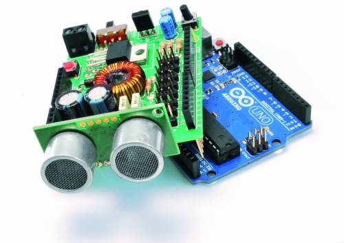
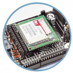
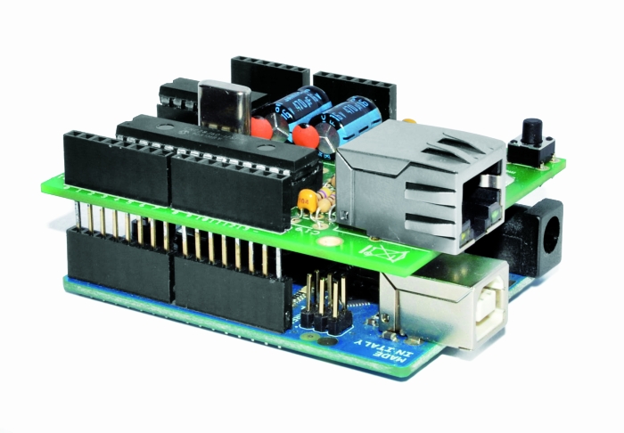
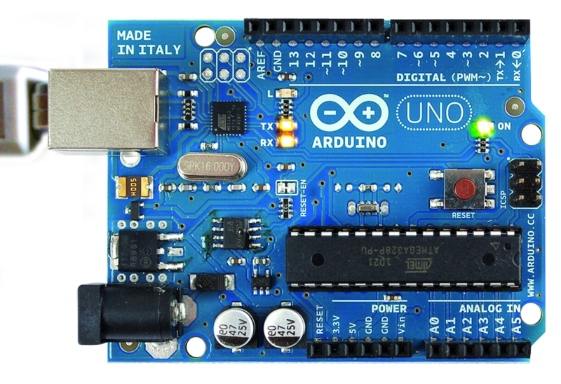
The idea behind this post is to bring together some robot designs and trasform them in a new device with new hardware and standard software (arduino of course) and so easier to use. These robots have three things in common: a mechanical structure, the hardware and the software. While the mechanical part is necessarily different, we wanted to understand if there was a hardware board that could be common, with a unique development system. The choice, quite obviously, has the Arduino board, which with its development environment is perfect to create similar projects. The first consideration that came to our mind is like the Arduino board can manage a large number of servos, eight in the case of the robot SPIDER. Arduino can be powered through the plug with a voltage between 6 to 12 volts, his voltage regulator provides the 5 V stabilized, necessary for the operation of our shield. We could power our robot with rechargeable batteries. A standard servo requires a supply voltage of 4.8 to 6 volts, easily obtainable with four batteries in series, at full charge, provide 1.5 x 4 = 6 volts but towards the complete discharge provide just 1.0 x 4 = 4 volts. We are not in optimal conditions for the servos. Throughout this reasons we decided to create a special shield, already prepared for all these functions, it is easy to install and use.
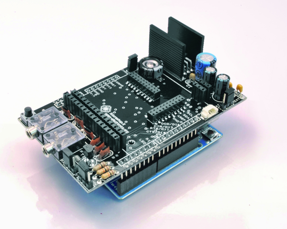
We see now the considerations that led us to the design of this shield:
must have a high voltage range
will provide a stabilized output for the servos
will provide power to the Arduino
must be equipped with an obstacle sensor
must have a receiver for remote control
must read the battery
We can assume to power our robot with a single battery pack with a voltage between 6 and 12 volts, so for example two cells or 6-8 LiPo NiMh or NiCd cells. The servos works at 5Volt, so we should get this stabilized voltage starting from input voltage of 6-12 volts. The optimal solution is the use of a switching step-down regulator which ensures efficiency exceeding 80% in every situation.

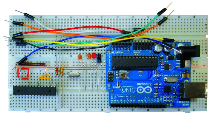
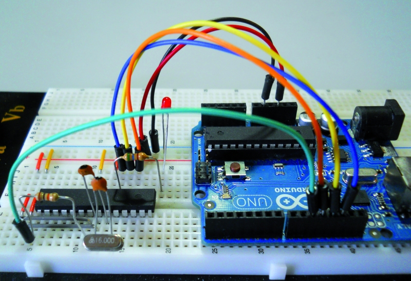
Just the integrated LM2576-5 contains all the elements to build a switching power supply, just add an inductor, a diode and a capacitor. It can deliver a maximum current of 3A and accepts input voltages between 4 and 40volt.

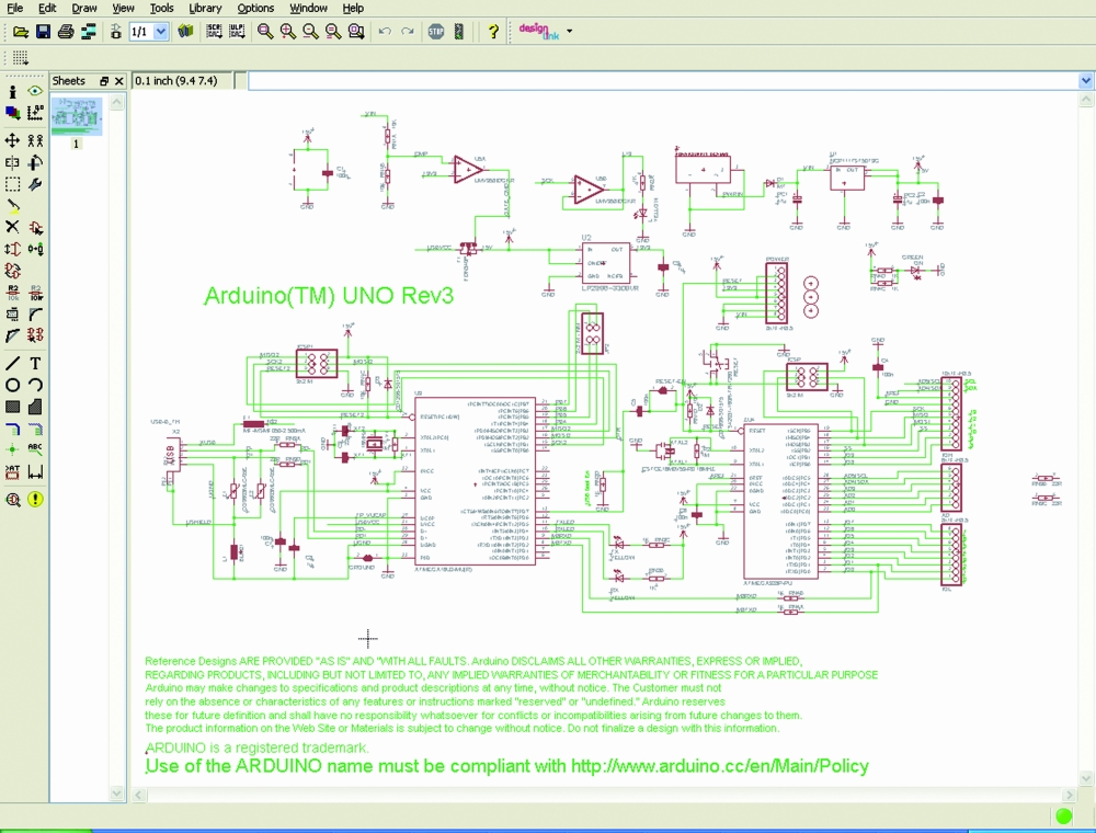
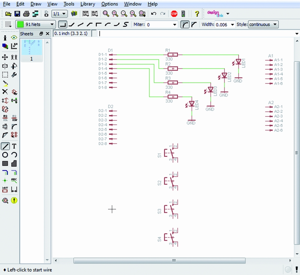
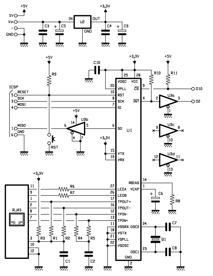
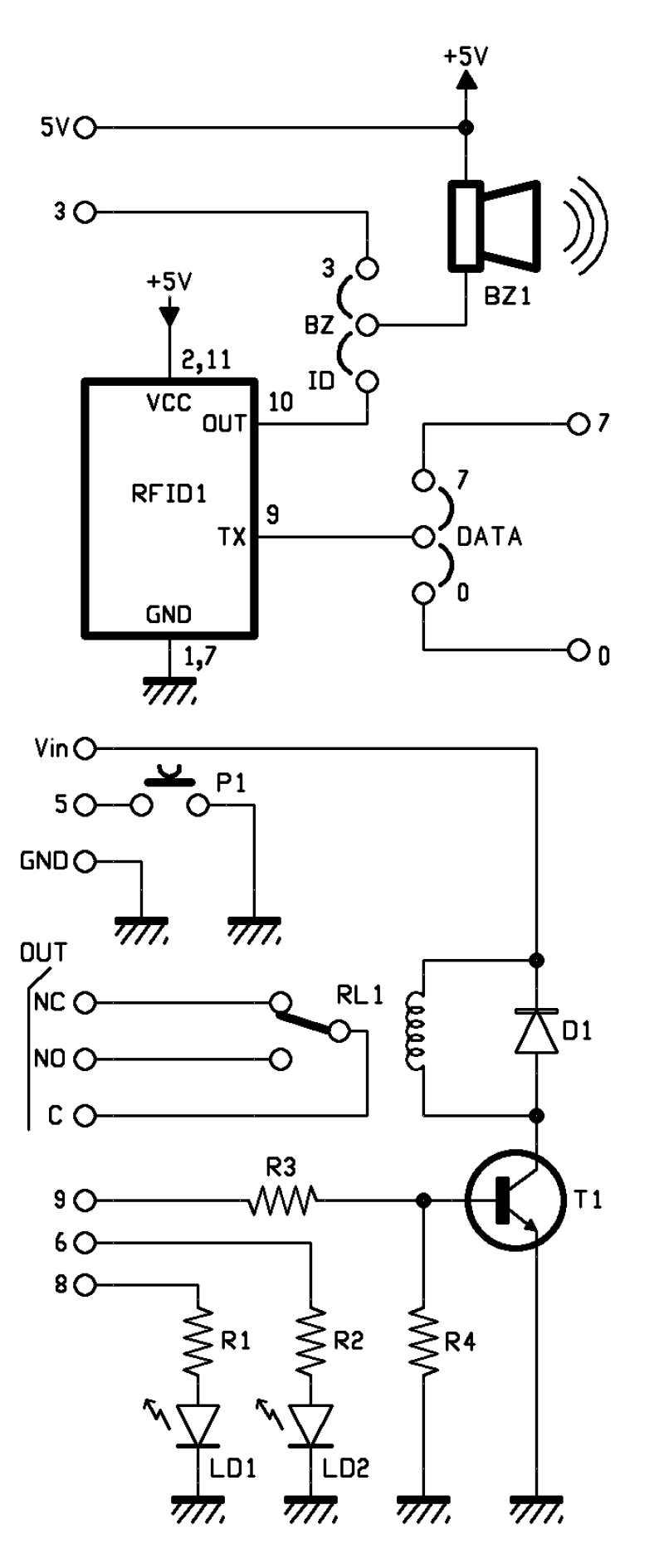
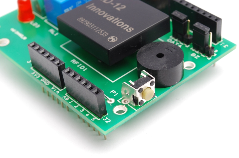
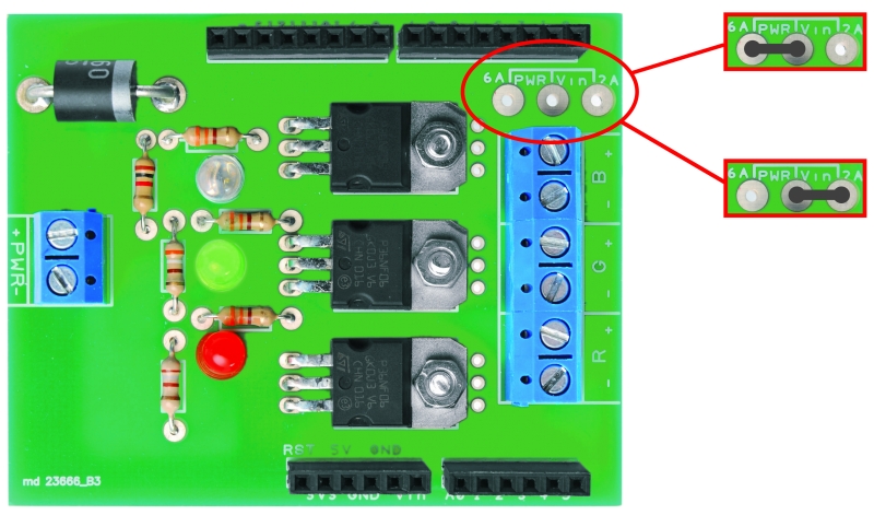
Analysing the wiring diagram you can see the connector BAT which will connect the battery pack to the switch and the voltage regulator LM2576, the resistance R5 and the led LD1 are used only to detect the presence of the voltage. The stabilized voltage output from the LM2576 will be used to power all the servos, while the Arduino is powered directly from the battery pack, taking the tension just after the switch (Vin).
For reading the battery voltage will use an analog input of Arduino (A0). The two resistors R1 and R2 reduce the voltage to a value between 0 and 20 volts to a value of 0-5Volt. We chose these specific values of resistance because, by reading the analog voltage with Arduino, it is sufficient to divide the data acquired by 50 to obtain the value of the voltage in volts.
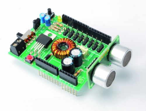
As obstacle sensor we chose the ultrasonic sensor model SRF05 that, thanks to its shape, recalls two eyes and improves the aesthetic appearance of our robot. To operate, we use a digital line connected to PIN11.
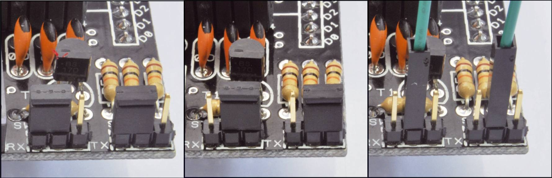
As remote control we opt for a economical infrared system; is sufficient to install an IR receiver compatible with the normal commercial remote controls, such as the integrated PNA4602. It will be sufficient a normal remote control of those used for TVs or VCRs to send commands to our robot in a simple and economic way. The shield provides the Arduino reset button, a button for general use and a LED connected to pin 13 of Arduino.

BOM
R1: 56 kohm
R2: 18 kohm
R3: 470 ohm
R4: 100 ohm
R5: 470 ohm
C1: 10 µF 63 VL
C2: 470 µF 25 VL
C3: 1000 µF 16 VL
C4: 100 nF
C5: 100 nF
C6: 10 µF 63 VL
LD1: LED 3 mm red
LD2: LED 3 mm green
U1: LM2576-5
SW1: switch
P1: Microswitch
RST: Microswitch
IR: IR38DM
L1: 100 µH 2A
D1: 1N5819
SRF05: SRF05
The Robot are three, corresponding to the robots Filippo, Bipe and Spider.
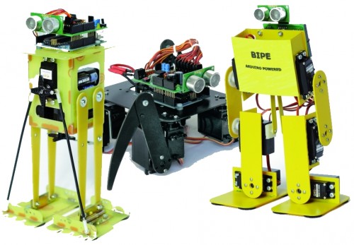
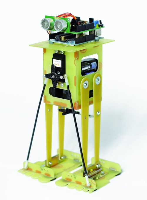
Filippo robot
Filippo is a biped robot whose movements are assigned to only two servos, but with this robot you can experiment with robotics without spending large sums. It is able to walk and turn around, then you can direct it in any direction, enabling those who are beginning to become familiar with the servos and how they can interact with mechanical parts. Its assembly is facilitated because all the pieces fit over each other and it is sufficient sorder to fix them permanently, as an alternative you can use the epoxy glue.
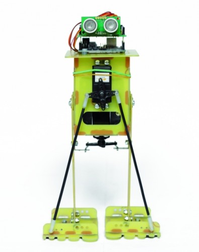
After the mechanical assembly, fix the Arduino board, with its shield, on top, the sensor SRF05 must look in front of the robot. The servos have to be wired as indicated in Table.
Connecting servos with Filippo robot
|
Servo
|
Arduino Pin |
Connector shiled |
Role |
| Servo 0 |
2 |
S1 |
Tilt (front servo) |
| Servo 1 |
3 |
S2 |
Step (servo in the bottom) |

For the power use 6 or 8 NiCd or NiMh rechargeable batteries size AA, they should be entered in two separate holder and connected in series. The battery holder are positioned one on the right and one on the left of the two servos, for their wiring must use two clips for batteries connected in series to 9 V.

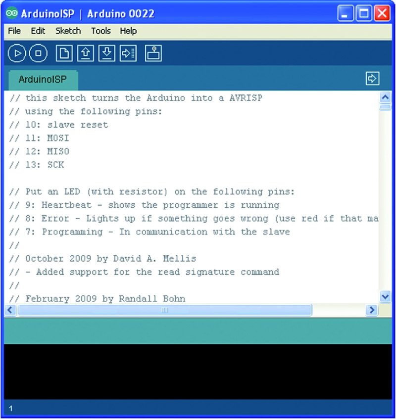
We recommend you to program the Arduino before connecting the servos to prevent any previous program provides the wrong signals to the servos that might go crazy.
Program Arduino with the sketch
// FILIPPO ARDUINO
// by Segatello Mirco per ElettronicaIN
// compilato con Arduino21

#include <Servo.h>
#include <IRremote.h>
#include <EEPROM.h>

#define RECV_PIN 10   // pin per sensore IR
#define PING_PIN 11   // pin per sensore RADAR
#define       P1 12   // pin per pulsante

#define STNB_CODE1 0x81D    // Stop Philips TV remote (AZIONE STOP)
#define STNB_CODE2 0x1D     // Codice alternativo
#define WALK_CODE1 0x81C    // Play Philips TV remote (AZIONE CAMMINA)
#define WALK_CODE2 0x1C     // Codice alternativo
#define SPEEDUP_CODE1 0x820 // Prg+ Philips TV remote (AZIONE PIù VELOCE)
#define SPEEDUP_CODE2 0x20  // Codice alternativo
#define SPEEDDW_CODE1 0x821 // Prg- Philips TV remote (AZIONE PIù LENTA))
#define SPEEDDW_CODE2 0x21  // Codice alternativo
#define LEFT_CODE1    0x2C  // Left Philips remote (RUOTA SX)
#define LEFT_CODE2    0x82C  // Codice alternativo
#define RIGHT_CODE1    0x2B  // Right Philips remote (ROUTA DX)
#define RIGHT_CODE2    0x82B  // Codice alternativo

#define MODE_OFF       0    // Servi OFF
#define MODE_STANDBY   1    // Servi armati in posizione di riposo
#define MODE_INWALK    2    // Assume la posizione di partenza
#define MODE_WALK      3    // Cammina in avanti
#define MODE_INSTANDBY 4    // Assume la posizione di standby
#define MODE_LEFT      5    // Si gira verso sinistra
#define MODE_RIGHT     6    // Si gira a destra
#define MODE_REVWALK   7    // Cammina all'indietro

IRrecv irrecv(RECV_PIN);
decode_results results;

int RobotMode = MODE_OFF;
int TimeOneStep = 2000;     // Velocità di esecuzione
int AmpPasso = 30;          // Ampiezza del passo (da 5 a 40)
int IncPasso = 15;          // Inlinazione durante la camminata (da 5 a 20)
int AmpRuota = 30;          // Ampiezza delle gambe durante la rotazione (da 5 a 40)
int IncRuota = 18;          // Inclinazione durante la rotazione (da 5 a 20)

Servo servo0, servo1;       // oggetti servo

int leg_ntr[8] = {90, 90};  //posizione neutrale dei servi
int leg_old[8] = {90, 90};  //posizione precedente dei servi
int leg[8];                 //posizione attuale dei servi
int i;

void setup()
{
  Serial.begin(9600);       // Start seriale
  Serial.println("FILIPPO Aduino V1.0");
  irrecv.enableIRIn();      // Start ricevitore IR
  irrecv.blink13(true);     // Lampeggio LED in ricezione IR attivo
  pinMode(P1, INPUT);       // Pulsante
  digitalWrite(P1, HIGH);   // Abilita pull-up
  levelBat();               // Verifica stato batteria
  Serial.println("Livello batteria OK.");
  Serial.println("Recupero dati posizione neutro servi...");
  readNeutral();
  Serial.println("Inizializzo Servi...");
  initServo();              // Inizializza servi
  Serial.println("Invia 'obs' per testare il sensore di ostacoli");
  Serial.println("Invia 'lev' per testare il livello della batteria");
  inStandby();              // Robot in attesa di comando
}

void loop()
{
  if (irrecv.decode(&results)) IRcommand();
  if (RobotMode==MODE_WALK)   walk();
  if (RobotMode==MODE_LEFT)   leftWalk();
  if (RobotMode==MODE_RIGHT)   rightWalk();

  if (digitalRead(P1)==0) P1Press();

  if (RobotMode==MODE_STANDBY)
  {
    if (Serial.available() > 2 )  ReceiveData();
  }
  else
  {
    // verifica livello batteria e presenza ostacoli
    levelBat();
    int obstacle = readDistance();
    if (obstacle < 20){
      Serial.println("Rilevato ostacolo!");
      inStandby();  }
  }
}

void readNeutral()
{
  // Recupera dalla EEPROM la posizione neutrale dei servi
  byte value;
  Serial.print("Neutro dei Servi: ");
  for (byte adress=0; adress<2; adress++)
  {
     value = EEPROM.read(adress);
     if ((80<value) && (value<100))
     {
          leg_ntr[adress] = value;
          Serial.print(value, DEC);
          Serial.print("  ");
     }
     else
     {
       leg_ntr[adress] = 90;
     }
   }
   Serial.println();
}

void ReceiveData()
{
    // Arrivati dati dalla USB
    byte startbyte, data_hight, data_low, data;
    Serial.print("Receive data USB     ");
    startbyte = Serial.read();
    data_hight = Serial.read();
    data_low= Serial.read();
    // richiesta livello batteria
    if ( (startbyte=='l') && (data_hight=='e') && (data_low=='v'))
    {
      levelBat();
      Serial.flush();  // svuota il buffer in ricezione
      exit;
    }
    // richiesta distanza ostacolo
    if ( (startbyte=='o') && (data_hight=='b') && (data_low=='s'))
    {
      int obstacle = readDistance();
      Serial.print("Ostacolo a ");
      Serial.print(obstacle, DEC);
      Serial.println(" cm");
      if (obstacle<20)  inStandby();
      Serial.flush();  // svuota il buffer in ricezione
      exit;
    }
    // impostazione neutro servo
    if ((data_hight >= '0') && (data_hight <= '9') && (data_low >= '0') && (data_low <= '9')) {
      data = (data_hight-48)*10+(data_low-48);
      if ((80 <= data) && (data <= 100)) {
         if (startbyte=='a') {
           leg_ntr[0] = data;
           EEPROM.write(0, data);
           printValue('a', data);
         }
         if (startbyte=='b') {
           leg_ntr[1] = data;
           EEPROM.write(1, data);
           printValue('b', data);
         }
      inStandby();         // aggiorna posizione neutro dei servi
      }
    }
    Serial.flush();  // svuota il buffer in ricezione
}

void printValue(byte servo, byte dt)
{
  Serial.print ("Set Servo: ");
  Serial.print (servo);
  Serial.print (" to ");
  Serial.println(dt,DEC);
}

void IRcommand()
{
    // E' arrivato un comando via IR
    Serial.print("IR code= ");
    Serial.println(results.value, HEX);  // ECO su serial monitor per sapere il codice arrivato

    if (results.value == WALK_CODE1 || results.value == WALK_CODE2)  inWalk();
    else if (results.value == LEFT_CODE1 || results.value == LEFT_CODE2)  inLeft();
    else if (results.value == RIGHT_CODE1 || results.value == RIGHT_CODE2)  inRight();
    else if (results.value == STNB_CODE1 || results.value == STNB_CODE2)  inStandby();

    else if (results.value == SPEEDUP_CODE1 || results.value == SPEEDUP_CODE2) {
      if (TimeOneStep > 1000) TimeOneStep -= 500; }
    else if (results.value == SPEEDDW_CODE1 || results.value == SPEEDDW_CODE2) {
      if (TimeOneStep < 4000) TimeOneStep += 500; }
    Serial.print("TimeOneStep= ");
    Serial.println(TimeOneStep);
    irrecv.resume(); // Resume decoding
}

void P1Press()
{
  // E' stato premuto il pulsante
  while (digitalRead(P1)==0) delay(100);
  if (RobotMode==MODE_WALK)  inStandby();
  else if (RobotMode==MODE_STANDBY) inWalk();
}

void levelBat()
{
  // controllo livello batteria
  int VbatRAW = analogRead(A0);
  float Vbat = float(VbatRAW)/50;
  Serial.print("Vbat= ");
  Serial.println(Vbat, DEC);
  if (Vbat<6.0)   {
    Serial.println("Livello batteria basso!");
    inOff();
  }
}

void initServo()
{
  // posizione iniziale dei servi
  servo0.attach(2);  // connette servo
  delay(200);
  servo1.attach(3);  // connette servo
  delay(200);
  Serial.println("Servi inizializzati.");
}

void inOff()
{
  // Spegne tutti i servi
  leg[0] = leg_ntr[0];
  leg[1] = leg_ntr[1];
  setServo();
  servo0.detach();  // sconnette servo
  servo1.detach();  // sconnette servo
  RobotMode = MODE_OFF;
  // Da questo modalità si deve spegnere il robot e ricaricare le batterie
}

void inStandby()
{
  // Posiziono tutti i servi in posizione neutrale
  leg[0] = leg_ntr[0];
  leg[1] = leg_ntr[1];
  setServo();
  RobotMode = MODE_STANDBY;
  Serial.println("Sono in Standby...");
}

void inWalk()
{
  // Si porta in posizione di passo partendo da fermo
  leg[0] = leg_ntr[0]+IncPasso;//inclinazione
  leg[1] = leg_ntr[1];
  setServo();

  RobotMode = MODE_WALK;
  Serial.println("Walk Mode...");
}

void walk()
{
  // Coordinate per eseguire un passo
  leg[0] = leg_ntr[0]+IncPasso;//piede SX in avanti
  leg[1] = leg_ntr[1]+AmpPasso;
  setServo();

  leg[0] = leg_ntr[0]-IncPasso;//inclinazione
  leg[1] = leg_ntr[1]+AmpPasso;
  setServo();

  leg[0] = leg_ntr[0]-IncPasso;//passo DX
  leg[1] = leg_ntr[1]-AmpPasso;
  setServo();

  leg[0] = leg_ntr[0]+IncPasso;//inclinazione
  leg[1] = leg_ntr[1]-AmpPasso;
  setServo();
}

void inLeft()
{
  // Si porta in posizione per ruotare
  leg[0] = leg_ntr[0]+IncRuota;//inclinazione
  leg[1] = leg_ntr[1];
  setServo();

  RobotMode = MODE_LEFT;
  Serial.println("Left Mode...");
}

void leftWalk()
{
      //passo 1
  leg[0] = leg_ntr[0]+IncRuota;//fa un passo
  leg[1] = leg_ntr[1]-AmpRuota;
  setServo();

      //passo 2
  leg[0] = leg_ntr[0];//piedi paralleli
  leg[1] = leg_ntr[1]-AmpRuota;
  setServo();

      //passo 3
  leg[0] = leg_ntr[0];//sforbiciata
  leg[1] = leg_ntr[1]+AmpRuota;
  setServo();

      //passo 4
  leg[0] = leg_ntr[0]-IncRuota;//inclinazione
  leg[1] = leg_ntr[1]+AmpRuota;
  setServo();

      //passo 5
  leg[0] = leg_ntr[0]-IncRuota;//passo
  leg[1] = leg_ntr[1]-AmpRuota;
  setServo();

       //passo 6
  leg[0] = leg_ntr[0];//piedi paralleli
  leg[1] = leg_ntr[1]-AmpRuota;
  setServo();

      //passo 7
  leg[0] = leg_ntr[0];//sforbiciata
  leg[1] = leg_ntr[1]+AmpRuota;
  setServo();

      //passo 8
  leg[0] = leg_ntr[0]+IncRuota;//sforbiciata
  leg[1] = leg_ntr[1]+AmpRuota;
  setServo();
}

void inRight()
{
  // Si porta in posizione per ruotare
      //passo 0  inclinazione
  leg[0] = leg_ntr[0]+IncRuota;
  leg[1] = leg_ntr[1];
  setServo();

  RobotMode = MODE_RIGHT;
  Serial.println("Right Mode...");
}

void rightWalk()
{
      //passo 1  passo
  leg[0] = leg_ntr[0]+IncRuota;
  leg[1] = leg_ntr[1]+AmpRuota;
  setServo();

      //passo 2 piedi paralleli
  leg[0] = leg_ntr[0];
  leg[1] = leg_ntr[1]+AmpRuota;
  setServo();

      //passo 3  sforbiciata
  leg[0] = leg_ntr[0];
  leg[1] = leg_ntr[1]-AmpRuota;
  setServo();

      //passo 4 inclinazione
  leg[0] = leg_ntr[0]-IncRuota;
  leg[1] = leg_ntr[1]-AmpRuota;
  setServo();

      //passo 5  passo
  leg[0] = leg_ntr[0]-IncRuota;
  leg[1] = leg_ntr[1]+AmpRuota;
  setServo();

       //passo 6 piedi paralleli
  leg[0] = leg_ntr[0];
  leg[1] = leg_ntr[1]+AmpRuota;
  setServo();

      //passo 7 sforbiciata
  leg[0] = leg_ntr[0];
  leg[1] = leg_ntr[1]-AmpRuota;
  setServo();

      //passo 8 inclinazione
  leg[0] = leg_ntr[0]+IncRuota;
  leg[1] = leg_ntr[1]-AmpRuota;
  setServo();
}

void setServo()
{
   // Posiziona i servi alle coordinate specificate da leg[]
   for (i=0; i<18; i++) {
       servo0.write(leg_old[0] + i*(leg[0]-leg_old[0])/18);
       servo1.write(leg_old[1] + i*(leg[1]-leg_old[1])/18);
       delay(TimeOneStep/4/18);
    }
    leg_old[0]=leg[0];
    leg_old[1]=leg[1];
}

long readDistance()
{
  // Procedura per leggere la presenza di ostacoli
  // Viene generato un PING di 2usec ed atteso l'ECO di risposta
  long duration, cm;
  pinMode(PING_PIN, OUTPUT);
  digitalWrite(PING_PIN, LOW);
  delayMicroseconds(2);
  digitalWrite(PING_PIN, HIGH);
  delayMicroseconds(5);
  digitalWrite(PING_PIN, LOW);

  // Lo stesso pin che genera il trigger è usato per la lettura
  // del segnale di ritorno
  pinMode(PING_PIN, INPUT);
  duration = pulseIn(PING_PIN, HIGH);

  // ritorna distanza ostacolo in cm
  return duration / 29 / 2;
}
Send the serial command ‘obs‘ for read the sensor SRF05 and the command ‘lev‘ to check the battery level. Make sure that the voltage read corresponds to the real value of the batteries, simply make a voltage measurement with a multimeter. Now set the neutral of the servos, in fact the robot to function properly must be perfectly centered. To center the servo which acts to tilt the robot you have to send the command ‘axx‘ where xx is the position. This data can assume values between 80 and 100 with the center point 90, if you can not set the servo to remain within these values you have to physically move the servo. You can modify this value if it found a tendency to deviate from the straight line when walking. Now regulate the step servo and sets the neutral with bxx command, where xx is the position to be allocated (value between 80 and 100). You are now ready for test, you can use the remote control to activate functions or use the button on the shield but it will only start the walk.

All functions have a speed of execution that can be changed by remote control with keys prog+ and prog-, many other parameters can be modified to adapt the software to different operating requirements.
The sketch begins by including the libraries dedicated to the use of the servos, the IR control and management of EEPROM:
Code 1
#include <Servo.h>
#include <IRremote.h>
#include <EEPROM.h>
The servo library is already implemented in the IDE of Arduino.
The EEPROM library, also available, provides controls to manage the non-volatile memory, we use it to save the position of the neutral servos so as not having to set each time.
The third library IRremote is used to manage the robot by remote control and must be downloaded from http://github.com/shirriff/Arduino-IRremote, for its operation is sufficient to specify which pin is connected to the sensor receiving IR signals (D10 in our shield). To find out if they arrived from the sensor data must test the status of the variable irrecv.decode (& results), but the code is contained in the variable came results.value.
Just compare the code recived with the reference code for the remote to know which button was pressed, so we specify at the beginning of the sketch of the codes for each button.
Code 2
#define STNB_CODE1 0x81D    // Stop Philips TV remote (STOP)
#define STNB_CODE2 0x1D     // alternative code
#define WALK_CODE1 0x81C    // Play Philips TV remote (WALK)
#define WALK_CODE2 0x1C // alternative code
#define SPEEDUP_CODE1 0x820 // Prg+ Philips TV remote (+ SPEED)
#define SPEEDUP_CODE2 0x20  // alternative code
#define SPEEDDW_CODE1 0x821 // Prg- Philips TV remote (-SPEED)
#define SPEEDDW_CODE2 0x21  // alternative code
#define LEFT_CODE1    0x2C  // Left Philips remote (SX wheel)
#define LEFT_CODE2    0x82C  // alternative code
#define RIGHT_CODE1    0x2B  // Right Philips remote (DX wheel)
#define RIGHT_CODE2    0x82B  // alternative code
As you can see each button is associated with two codes (CODE1 and CODE2) this is because the codes are sent alternately every time you press the button, instead of repeating the same code if the button is pressed. So if you press the play button will send the code 0x81C and so long as the button is pressed, if you release the button and press it sends the code 0x1C, so alternately.
The sketch is intended for use with remote controls which use the encoding Philips, the most commonly used in television. If you use a different remote control the code of the buttons do not match and you have to change the codes listed above.

Now let’s see what parameters can be modified by the program to adapt the movements:
Code 3
int TimeOneStep = 2000;
int AmpPasso = 30;
int IncPasso = 15;
int AmpRuota = 30;
int IncRuota = 18;
TimeOneStep is the initial value of the time taken to perform a step, can be changed by remote control from a minimum of 1 sec to a maximum of 4 sec.
AmpPasso is the maximum amplitude in degrees of opening of the legs during walking, its value can vary from a minimum of 5 to a maximum of 40.
IncPasso is the maximum inclination of the robot during the walk, its value can vary from a minimum of 5 to a maximum of 20. This value is to ensure the robot to keep balance on one leg while performing a step.
AmpRuota is the maximum amplitude in degrees of opening of the legs during the rotation, its value can change from a minimum of 5 to a maximum of 40.
IncRuota is the maximum inclination of the robot during the rotation, its value can change from a minimum of 5 to a maximum of 20.
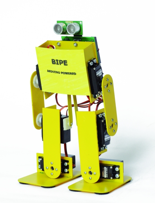
ROBOT BIPE
We see now to the second robot, is called BIPE.
The mechanical is made of PCB and assembly is made by soding together the various components to ensure the strength needed to support the weight of the components.

The control board based on Arduino + shield is positioned on the back of the robot while the battery pack, should be placed at the front. Let’s say that for our tests we used a battery composed of two cell 850mAh LiPo which, being small and light, are easily placed and not weigh down the structure. To properly position the sensor SRF05 you must use a small adapter with a strip made of male-female, as those used on the Arduino shield, angled 90 °.

Connecting servos with robot BIPE
| Servo |
Arduino Pin |
Connector shield |
Function |
| Servo 0 |
2 |
S1 |
left hip |
| Servo 1 |
3 |
S2 |
left knee |
| Servo 2 |
4 |
S3 |
left foot |
| Servo 3 |
5 |
S4 |
right hip |
| Servo 4 |
6 |
S5 |
right knee |
| Servo 5 |
7 |
S6 |
right foot |
For setting follow the same instructions for the robot Filippo, the sketch retains the same structure of the software used with Filippo, with the necessary modifications and add.
// BIPE ARDUINO
// by Segatello Mirco per ElettronicaIN
// compilato con Arduino21

#include <Servo.h>
#include <IRremote.h>
#include <EEPROM.h>

#define RECV_PIN 10   // pin per sensore IR
#define PING_PIN 11   // pin per sensore RADAR
#define       P1 12   // pin per pulsante

#define STNB_CODE1 0x81D    // Stop Philips TV remote
#define STNB_CODE2 0x1D     // Codice alternativo
#define WALK_CODE1 0x81C    // Play Philips TV remote
#define WALK_CODE2 0x1C     // Codice alternativo
#define SPEEDUP_CODE1 0x820 // Prg+ Philips TV remote
#define SPEEDUP_CODE2 0x20  // Codice alternativo
#define SPEEDDW_CODE1 0x821 // Prg- Philips TV remote
#define SPEEDDW_CODE2 0x21  // Codice alternativo
#define LEFT_CODE1    0x2C  // Left Philips remote
#define LEFT_CODE2    0x82C  // Codice alternativo
#define RIGHT_CODE1    0x2B  // Right Philips remote
#define RIGHT_CODE2    0x82B  // Codice alternativo
#define VOLUP_CODE1   0x810 // Volume+
#define VOLUP_CODE2   0x10  // codice alternativo
#define VOLDW_CODE1   0x811 //Volume-
#define VOLDW_CODE2   0x11 //codice alternativo

#define PRG1_CODE1 0x801 // Program 1
#define PRG1_CODE2 0x1 // Program 1
#define PRG2_CODE1 0x802 // Program 2
#define PRG2_CODE2 0x2 // Program 2

#define MODE_OFF       0    // Servi OFF
#define MODE_STANDBY   1    // Servi armati in posizione di riposo
#define MODE_INWALK    2    // Assume la posizione di partenza
#define MODE_WALK      3    // Cammina in avanti
#define MODE_INSTANDBY 4    // Assume la posizione di standby
#define MODE_LEFT      5    // Si gira verso sinistra
#define MODE_RIGHT     6    // Si gira a destra
#define MODE_REVWALK   7    // Cammina all'indietro

IRrecv irrecv(RECV_PIN);
decode_results results;

int RobotMode = MODE_OFF;
int TimeOneStep = 4000;     // Velocità di esecuzione
int AmpPasso = 10;          // Ampiezza del passo (da 5 a 20)
int AmpRuota = 12;          // Ampiezza durante la rotazione (da 5 a 20)
int IncPasso = 8;           // Inlinazione durante la camminata (da 5 a 10)

Servo servo0, servo1, servo2, servo3,
      servo4, servo5, servo6, servo7;  // oggetti servo
      // Servo 6 e 7 possono essere usati per le braccia!

int leg_ntr[8] = {90, 90, 90, 90, 90, 90, 90, 90}; //posizione neutrale dei servi
int leg_old[8] = {90, 90, 90, 90, 90, 90, 90, 90}; //posizione precedente dei servi
int leg[8];                 //posizione attuale dei servi
int i;

void setup()
{
  Serial.begin(9600);       // Start seriale
  Serial.println("SIDERIN Aduino V1.0");
  irrecv.enableIRIn();      // Start ricevitore IR
  irrecv.blink13(true);     // Lampeggio LED in ricezione IR attivo
  pinMode(P1, INPUT);       // Pulsante
  digitalWrite(P1, HIGH);   // Abilita pull-up
  levelBat();               // Verifica stato batteria
  Serial.println("Livello batteria OK.");
  Serial.println("Recupero dati posizione neutro servi...");
  readNeutral();
  Serial.println("Inizializzo Servi...");
  initServo();              // Inizializza servi
  Serial.println("Invia 'obs' per testare il sensore di ostacoli");
  Serial.println("Invia 'lev' per testare il livello della batteria");
  inStandby();              // Robot in attesa di comando
}

void loop()
{
  if (irrecv.decode(&results)) IRcommand();
  if (RobotMode==MODE_WALK)   walk();
//  if (RobotMode==MODE_REVWALK) walkReverse();
  if (RobotMode==MODE_LEFT)   leftWalk();
  if (RobotMode==MODE_RIGHT)   rightWalk();

  if (digitalRead(P1)==0) P1Press();

  if (RobotMode==MODE_STANDBY)
  {
    if (Serial.available() > 2 )  ReceiveData();
  }
  else
  {
    levelBat();
    int obstacle = readDistance();
    if (obstacle < 20)  inStandby();
  }
}

void readNeutral()
{
  // Recupera dalla EEPROM la posizione neutrale dei servi
  byte value;
  Serial.print("Neutro dei Servi: ");
  for (byte adress=0; adress<6; adress++)
  {
     value = EEPROM.read(adress);
     if ((80<value) && (value<100))
     {
          leg_ntr[adress] = value;
          Serial.print(value, DEC);
          Serial.print("  ");
     }
     else
     {
       leg_ntr[adress] = 90;
     }
   }
   Serial.println();
}

void ReceiveData()
{
    // Arrivati dati dalla USB
    byte startbyte, data_hight, data_low, data;
    Serial.print("Receive data USB     ");
    startbyte = Serial.read();
    data_hight = Serial.read();
    data_low= Serial.read();
    // richiesta livello batteria
    if ( (startbyte=='l') && (data_hight=='e') && (data_low=='v'))
    {
      levelBat();
      Serial.flush();  // svuota il buffer in ricezione
      exit;
    }
    // richiesta distanza ostacolo
    if ( (startbyte=='o') && (data_hight=='b') && (data_low=='s'))
    {
      int obstacle = readDistance();
      Serial.print("Ostacolo a ");
      Serial.print(obstacle, DEC);
      Serial.println(" cm");
      if (obstacle<20)  inStandby();
      Serial.flush();  // svuota il buffer in ricezione
      exit;
    }
    // impostazione neutro servo
    if ((data_hight >= '0') && (data_hight <= '9') && (data_low >= '0') && (data_low <= '9')) {
      data = (data_hight-48)*10+(data_low-48);
      if ((80 <= data) && (data <= 100)) {
         if (startbyte=='a') {
           leg_ntr[0] = data;
           EEPROM.write(0, data);
           printValue('a', data);
         }
         if (startbyte=='b') {
           leg_ntr[1] = data;
           EEPROM.write(1, data);
           printValue('b', data);
         }
         if (startbyte=='c') {
           leg_ntr[2] = data;
           EEPROM.write(2, data);
           printValue('c', data);
         }
         if (startbyte=='d') {
           leg_ntr[3] = data;
           EEPROM.write(3, data);
           printValue('d', data);
         }
         if (startbyte=='e') {
           leg_ntr[4] = data;
           EEPROM.write(4, data);
           printValue('e', data);
         }
         if (startbyte=='f') {
           leg_ntr[5] = data;
           EEPROM.write(5, data);
           printValue('f', data);
         }
      inStandby();         // aggiorna posizione neutro dei servi
      }
    }
    Serial.flush();  // svuota il buffer in ricezione
}

void printValue(byte servo, byte dt)
{
  Serial.print ("Set Servo: ");
  Serial.print (servo);
  Serial.print (" to ");
  Serial.println(dt,DEC);
}

void IRcommand()
{
    // E' arrivato un comando via IR
    Serial.println(results.value, HEX);  // ECO su serial monitor per sapere il codice arrivato

    if (results.value == WALK_CODE1 || results.value == WALK_CODE2)   inWalk();
    else if (results.value == LEFT_CODE1 || results.value == LEFT_CODE2)  inLeft();
    else if (results.value == RIGHT_CODE1 || results.value == RIGHT_CODE2)  inRight();
    else if (results.value == STNB_CODE1 || results.value == STNB_CODE2)  inStandby();

    else if (results.value == PRG1_CODE1 || results.value == PRG1_CODE2) {
      if (RobotMode==MODE_STANDBY) kick(); }

    else if (results.value == PRG2_CODE1 || results.value == PRG2_CODE2)  {
       if (RobotMode==MODE_STANDBY)  bow(); }

    else if (results.value == SPEEDUP_CODE1 || results.value == SPEEDUP_CODE2) {
      if (TimeOneStep > 1000) TimeOneStep -= 200; }
    else if (results.value == SPEEDDW_CODE1 || results.value == SPEEDDW_CODE2) {
      if (TimeOneStep < 2000) TimeOneStep += 200; }
    Serial.print("TimeOneStep= ");
    Serial.println(TimeOneStep);
    irrecv.resume(); // Resume decoding
}

void P1Press()
{
  // E' stato premuto il pulsante
  while (digitalRead(P1)==0) delay(100);
  if (RobotMode==MODE_WALK)  inStandby();
  else if (RobotMode==MODE_STANDBY) inWalk();
}

void levelBat()
{
  // controllo livello batteria
  int VbatRAW = analogRead(A0);
  float Vbat = float(VbatRAW)/50;
  Serial.print("Vbat= ");
  Serial.println(Vbat, DEC);
  if (Vbat<6.0)   {
    Serial.println("Livello batteria basso!");
    inOff();
  }
}

void initServo()
{
  // posizione iniziale dei servi
  servo0.attach(2);  // connette servo
  delay(200);
  servo1.attach(3);  // connette servo
  delay(200);
  servo2.attach(4);  // connette servo
  delay(200);
  servo3.attach(5);  // connette servo
  delay(200);
  servo4.attach(6);  // connette servo
  delay(200);
  servo5.attach(7);  // connette servo
  delay(200);
  servo6.attach(8);  // connette servo
  delay(200);
  servo7.attach(9);  // connette servo
  delay(200);
  Serial.println("Servi inizializzati.");
}

void inOff()
{
  // Spegne tutti i servi
  leg[0] = leg_ntr[0];
  leg[1] = leg_ntr[1];
  leg[2] = leg_ntr[2];
  leg[3] = leg_ntr[3];
  leg[4] = leg_ntr[4];
  leg[5] = leg_ntr[5];
  leg[6] = 90;
  leg[7] = 90;
  setServo();
  servo0.detach();  // sconnette servo
  servo1.detach();  // sconnette servo
  servo2.detach();  // sconnette servo
  servo3.detach();  // sconnette servo
  servo4.detach();  // sconnette servo
  servo5.detach();  // sconnette servo
  servo6.detach();  // sconnette servo
  servo7.detach();  // sconnette servo
  RobotMode = MODE_OFF;
  // Da questo modalità si deve spegnere il robot e ricaricare le batterie
}

void inStandby()
{
  // Posiziono tutti i servi in posizione neutrale
  leg[0] = leg_ntr[0];
  leg[1] = leg_ntr[1];
  leg[2] = leg_ntr[2];
  leg[3] = leg_ntr[3];
  leg[4] = leg_ntr[4];
  leg[5] = leg_ntr[5];
  leg[6] = 90;
  leg[7] = 90;
  setServo();
  RobotMode = MODE_STANDBY;
  Serial.println("Sono in Standby...");
}

void inWalk()
{
  // Si porta in posizione di passo partendo da fermo
  leg[0] = leg_ntr[0];//inclinazione
  leg[1] = leg_ntr[1];
  leg[2] = leg_ntr[2]-IncPasso;
  leg[3] = leg_ntr[3];
  leg[4] = leg_ntr[4];
  leg[5] = leg_ntr[5]-IncPasso*2;
  setServo();
  leg[0] = leg_ntr[0]+AmpPasso;//passo DX da fermo
  leg[1] = leg_ntr[1]+AmpPasso;
  leg[2] = leg_ntr[2]-IncPasso;
  leg[3] = leg_ntr[3]+AmpPasso;
  leg[4] = leg_ntr[4]+AmpPasso;
  leg[5] = leg_ntr[5]-IncPasso*2;
  setServo();
  RobotMode = MODE_WALK;
  Serial.println("Walk Mode...");
}

void setServo()
{
   // Posiziona i servi alle coordinate specificate da leg[]
   for (i=0; i<18; i++) {
       servo0.write(leg_old[0] + i*(leg[0]-leg_old[0])/18);
       servo1.write(leg_old[1] + i*(leg[1]-leg_old[1])/18);
       servo2.write(leg_old[2] + i*(leg[2]-leg_old[2])/18);
       servo3.write(leg_old[3] + i*(leg[3]-leg_old[3])/18);
       servo4.write(leg_old[4] + i*(leg[4]-leg_old[4])/18);
       servo5.write(leg_old[5] + i*(leg[5]-leg_old[5])/18);
       servo6.write(leg_old[6] + i*(leg[6]-leg_old[6])/18);
       servo7.write(leg_old[7] + i*(leg[7]-leg_old[7])/18);
       delay(TimeOneStep/4/18);
    }
    leg_old[0]=leg[0];
    leg_old[1]=leg[1];
    leg_old[2]=leg[2];
    leg_old[3]=leg[3];
    leg_old[4]=leg[4];
    leg_old[5]=leg[5];
    leg_old[6]=leg[6];
    leg_old[7]=leg[7];
}

void      setServoWalk()
{
};

void walk()
{
  // Coordinate per eseguire un passo
  leg[0] = leg_ntr[0]+AmpPasso;//inclinazione
  leg[1] = leg_ntr[1]+AmpPasso;
  leg[2] = leg_ntr[2]+IncPasso*2;
  leg[3] = leg_ntr[3]+AmpPasso;
  leg[4] = leg_ntr[4]+AmpPasso;
  leg[5] = leg_ntr[5]+IncPasso;
  setServo();
  if (RobotMode!=MODE_WALK) return;

  leg[0] = leg_ntr[0]-AmpPasso;//passo SX
  leg[1] = leg_ntr[1]-AmpPasso;
  leg[2] = leg_ntr[2]+IncPasso*2;
  leg[3] = leg_ntr[3]-AmpPasso;
  leg[4] = leg_ntr[4]-AmpPasso;
  leg[5] = leg_ntr[5]+IncPasso;
  setServo();
  if (RobotMode!=MODE_WALK) return;

  leg[0] = leg_ntr[0]-AmpPasso;//inclinazione
  leg[1] = leg_ntr[1]-AmpPasso;
  leg[2] = leg_ntr[2]-IncPasso;
  leg[3] = leg_ntr[3]-AmpPasso;
  leg[4] = leg_ntr[4]-AmpPasso;
  leg[5] = leg_ntr[5]-IncPasso*2;
  setServo();
  if (RobotMode!=MODE_WALK) return;

  leg[0] = leg_ntr[0]+AmpPasso;//passo DX
  leg[1] = leg_ntr[1]+AmpPasso;
  leg[2] = leg_ntr[2]-IncPasso;
  leg[3] = leg_ntr[3]+AmpPasso;
  leg[4] = leg_ntr[4]+AmpPasso;
  leg[5] = leg_ntr[5]-IncPasso*2;
  setServo();
}

void inLeft()
{
  // Si posiziona pronto per girare a sinistra
  leg[0] = leg_ntr[0];//inclinazione SX
  leg[1] = leg_ntr[1];
  leg[2] = leg_ntr[2]-IncPasso;
  leg[3] = leg_ntr[3];
  leg[4] = leg_ntr[4];
  leg[5] = leg_ntr[5]-IncPasso*2;
  setServo();

  leg[0] = leg_ntr[0];//piede DX avanti
  leg[1] = leg_ntr[1];
  leg[2] = leg_ntr[2]-IncPasso;
  leg[3] = leg_ntr[3]+AmpRuota;
  leg[4] = leg_ntr[4]+AmpRuota;
  leg[5] = leg_ntr[5]-IncPasso*2;
  setServo();

  leg[0] = leg_ntr[0];//inclinazione DX
  leg[1] = leg_ntr[1];
  leg[2] = leg_ntr[2]+IncPasso*2;
  leg[3] = leg_ntr[3]+AmpRuota;
  leg[4] = leg_ntr[4]+AmpRuota;
  leg[5] = leg_ntr[5]+IncPasso;
  setServo();

  leg[0] = leg_ntr[0]+AmpRuota;//piede SX indietro
  leg[1] = leg_ntr[1]+AmpRuota;
  leg[2] = leg_ntr[2]+IncPasso*2;
  leg[3] = leg_ntr[3]+AmpRuota;
  leg[4] = leg_ntr[4]+AmpRuota;
  leg[5] = leg_ntr[5]+IncPasso;
  setServo();

  leg[0] = leg_ntr[0]+AmpRuota;//piedi a terra
  leg[1] = leg_ntr[1]+AmpRuota;
  leg[2] = leg_ntr[2];
  leg[3] = leg_ntr[3]+AmpRuota;
  leg[4] = leg_ntr[4]+AmpRuota;
  leg[5] = leg_ntr[5];
  setServo();

  RobotMode = MODE_LEFT;
  Serial.println("Left Mode...");
}

void leftWalk()
{
      //passo 1
  leg[0] = leg_ntr[0]-AmpRuota;//sforbiciata
  leg[1] = leg_ntr[1]-AmpRuota;
  leg[2] = leg_ntr[2];
  leg[3] = leg_ntr[3]-AmpRuota;
  leg[4] = leg_ntr[4]-AmpRuota;
  leg[5] = leg_ntr[5];
  setServo();
      if (RobotMode!=MODE_LEFT) return;

      //passo 2
  leg[0] = leg_ntr[0]-AmpRuota;//inclinazione
  leg[1] = leg_ntr[1]-AmpRuota;
  leg[2] = leg_ntr[2]-IncPasso;
  leg[3] = leg_ntr[3]-AmpRuota;
  leg[4] = leg_ntr[4]-AmpRuota;
  leg[5] = leg_ntr[5]-IncPasso*2;
  setServo();
      if (RobotMode!=MODE_LEFT) return;

      //passo 3
  leg[0] = leg_ntr[0]-AmpRuota;//sposta piede DX in avanti
  leg[1] = leg_ntr[1]-AmpRuota;
  leg[2] = leg_ntr[2]-IncPasso;
  leg[3] = leg_ntr[3]+AmpRuota;
  leg[4] = leg_ntr[4]+AmpRuota;
  leg[5] = leg_ntr[5]-IncPasso*2;
  setServo();
      if (RobotMode!=MODE_LEFT) return;

      //passo 4
  leg[0] = leg_ntr[0]-AmpRuota;//inclinazione
  leg[1] = leg_ntr[1]-AmpRuota;
  leg[2] = leg_ntr[2]+IncPasso*2;
  leg[3] = leg_ntr[3]+AmpRuota;
  leg[4] = leg_ntr[4]+AmpRuota;
  leg[5] = leg_ntr[5]+IncPasso;
  setServo();
      if (RobotMode!=MODE_LEFT) return;

      //passo 5
  leg[0] = leg_ntr[0]+AmpRuota;//sposta SX indietro
  leg[1] = leg_ntr[1]+AmpRuota;
  leg[2] = leg_ntr[2]+IncPasso*2;
  leg[3] = leg_ntr[3]+AmpRuota;
  leg[4] = leg_ntr[4]+AmpRuota;
  leg[5] = leg_ntr[5]+IncPasso;
  setServo();
      if (RobotMode!=MODE_LEFT) return;

      //passo 6
  leg[0] = leg_ntr[0]+AmpRuota;//piedi a terra
  leg[1] = leg_ntr[1]+AmpRuota;
  leg[2] = leg_ntr[2];
  leg[3] = leg_ntr[3]+AmpRuota;
  leg[4] = leg_ntr[4]+AmpRuota;
  leg[5] = leg_ntr[5];
  setServo();
     if (RobotMode!=MODE_LEFT) return;
}

void inRight()
{
  // Si posiziona pronto per girare a sinistra
  leg[0] = leg_ntr[0];//inclinazione SX
  leg[1] = leg_ntr[1];
  leg[2] = leg_ntr[2]+IncPasso*2;
  leg[3] = leg_ntr[3];
  leg[4] = leg_ntr[4];
  leg[5] = leg_ntr[5]+IncPasso;
  setServo();

  leg[0] = leg_ntr[0]-AmpRuota;//piede DX avanti
  leg[1] = leg_ntr[1]-AmpRuota;
  leg[2] = leg_ntr[2]+IncPasso*2;
  leg[3] = leg_ntr[3];
  leg[4] = leg_ntr[4];
  leg[5] = leg_ntr[5]+IncPasso;
  setServo();

  leg[0] = leg_ntr[0]-AmpRuota;//inclinazione DX
  leg[1] = leg_ntr[1]-AmpRuota;
  leg[2] = leg_ntr[2]-IncPasso;
  leg[3] = leg_ntr[3];
  leg[4] = leg_ntr[4];
  leg[5] = leg_ntr[5]-IncPasso*2;
  setServo();

  leg[0] = leg_ntr[0]-AmpRuota;//piede SX indietro
  leg[1] = leg_ntr[1]-AmpRuota;
  leg[2] = leg_ntr[2]-IncPasso;
  leg[3] = leg_ntr[3]-AmpRuota;
  leg[4] = leg_ntr[4]-AmpRuota;
  leg[5] = leg_ntr[5]-IncPasso*2;
  setServo();

  leg[0] = leg_ntr[0]-AmpRuota;//piedi a terra
  leg[1] = leg_ntr[1]-AmpRuota;
  leg[2] = leg_ntr[2];
  leg[3] = leg_ntr[3]-AmpRuota;
  leg[4] = leg_ntr[4]-AmpRuota;
  leg[5] = leg_ntr[5];
  setServo();

  RobotMode = MODE_RIGHT;
  Serial.println("Right Mode...");
}

void rightWalk()
{
      //passo 1
  leg[0] = leg_ntr[0]+AmpRuota;//sforbiciata
  leg[1] = leg_ntr[1]+AmpRuota;
  leg[2] = leg_ntr[2];
  leg[3] = leg_ntr[3]+AmpRuota;
  leg[4] = leg_ntr[4]+AmpRuota;
  leg[5] = leg_ntr[5];
  setServo();
      if (RobotMode!=MODE_RIGHT) return;

      //passo 2
  leg[0] = leg_ntr[0]+AmpRuota;//inclinazione
  leg[1] = leg_ntr[1]+AmpRuota;
  leg[2] = leg_ntr[2]+IncPasso*2;
  leg[3] = leg_ntr[3]+AmpRuota;
  leg[4] = leg_ntr[4]+AmpRuota;
  leg[5] = leg_ntr[5]+IncPasso;
  setServo();
      if (RobotMode!=MODE_RIGHT) return;

      //passo 3
  leg[0] = leg_ntr[0]+AmpRuota;//sposta piede DX in avanti
  leg[1] = leg_ntr[1]+AmpRuota;
  leg[2] = leg_ntr[2]+IncPasso*2;
  leg[3] = leg_ntr[3]-AmpRuota;
  leg[4] = leg_ntr[4]-AmpRuota;
  leg[5] = leg_ntr[5]+IncPasso;
  setServo();
      if (RobotMode!=MODE_RIGHT) return;

      //passo 4
  leg[0] = leg_ntr[0]+AmpRuota;//inclinazione
  leg[1] = leg_ntr[1]+AmpRuota;
  leg[2] = leg_ntr[2]-IncPasso;
  leg[3] = leg_ntr[3]-AmpRuota;
  leg[4] = leg_ntr[4]-AmpRuota;
  leg[5] = leg_ntr[5]-IncPasso*2;
  setServo();
      if (RobotMode!=MODE_RIGHT) return;

      //passo 5
  leg[0] = leg_ntr[0]-AmpRuota;//sposta SX indietro
  leg[1] = leg_ntr[1]-AmpRuota;
  leg[2] = leg_ntr[2]-IncPasso;
  leg[3] = leg_ntr[3]-AmpRuota;
  leg[4] = leg_ntr[4]-AmpRuota;
  leg[5] = leg_ntr[5]-IncPasso*2;
  setServo();
      if (RobotMode!=MODE_RIGHT) return;

      //passo 6
  leg[0] = leg_ntr[0]-AmpRuota;//piedi a terra
  leg[1] = leg_ntr[1]-AmpRuota;
  leg[2] = leg_ntr[2];
  leg[3] = leg_ntr[3]-AmpRuota;
  leg[4] = leg_ntr[4]-AmpRuota;
  leg[5] = leg_ntr[5];
  setServo();
      if (RobotMode!=MODE_RIGHT) return;
}

void bow()
{
  //inchino
  leg[0] = leg_ntr[0]-60;
  leg[1] = leg_ntr[1]-10;
  leg[2] = leg_ntr[2];
  leg[3] = leg_ntr[3]+60;
  leg[4] = leg_ntr[4]+10;
  leg[5] = leg_ntr[5];
  setServo();
  delay(1000);
  leg[0] = leg_ntr[0];//passo DX da fermo
  leg[1] = leg_ntr[1];
  leg[2] = leg_ntr[2];
  leg[3] = leg_ntr[3];
  leg[4] = leg_ntr[4];
  leg[5] = leg_ntr[5];
  setServo();
}

void kick()
{
   //calcio
  leg[0] = leg_ntr[0];//inclinazione
  leg[1] = leg_ntr[1];
  leg[2] = leg_ntr[2]-12;//regolare questo valore per bilanciare
  leg[3] = leg_ntr[3];
  leg[4] = leg_ntr[4];
  leg[5] = leg_ntr[5]-24;
  setServo();
  leg[0] = leg_ntr[0];//piede indietro
  leg[1] = leg_ntr[1];
  leg[2] = leg_ntr[2]-12;//regolare questo valore per bilanciare
  leg[3] = leg_ntr[3]-AmpPasso;
  leg[4] = leg_ntr[4]+AmpPasso;
  leg[5] = leg_ntr[5];
  setServo();
  //calcia

       leg_old[3]=leg_ntr[3]+AmpPasso;
       servo3.write(leg_old[3]);
       leg_old[4]=leg_ntr[4]-AmpPasso;
       servo4.write(leg_old[4]);

  leg[0] = leg_ntr[0];//ritorna in posizione
  leg[1] = leg_ntr[1];
  leg[2] = leg_ntr[2];
  leg[3] = leg_ntr[3];
  leg[4] = leg_ntr[4];
  leg[5] = leg_ntr[5];
  setServo();

}

long readDistance()
{
  // Procedura per leggere la presenza di ostacoli
  // Viene generato un PING di 2usec ed atteso l'ECO di risposta
  long duration, cm;
  pinMode(PING_PIN, OUTPUT);
  digitalWrite(PING_PIN, LOW);
  delayMicroseconds(2);
  digitalWrite(PING_PIN, HIGH);
  delayMicroseconds(5);
  digitalWrite(PING_PIN, LOW);

  // Lo stesso pin che genera il trigger è usato per la lettura
  // del segnale di ritorno
  pinMode(PING_PIN, INPUT);
  duration = pulseIn(PING_PIN, HIGH);

  // ritorna distanza ostacolo in cm
  return duration / 29 / 2;
}
For this robot is important to the calibration of the neutral of the servos that occurs as previously described. Servo0 corresponds to the letter ‘a‘ – Servo5 corresponds to the letter ‘f‘. If the command is ok will receive confirmation of Serial Monitor, for example: “set servo: a to 90“.

This robot have additional functions such as the bow and football features that are not implemented on Filippo.
Code 4
#define PRG1_CODE1 0x801 // Program 1
#define PRG1_CODE2 0x1 // Program 1
#define PRG2_CODE1 0x802 // Program 2
#define PRG2_CODE2 0x2 // Program 2
To the button ’1 ‘corresponds to the function of football with which the robot can hit, for example a ball, to the button ’2′ corresponds to the bow that is always of great effect.
The parameters can be set by the program are similar to those of robot Filippo:
Code 5
int TimeOneStep = 4000;
int AmpPasso = 10;
int AmpRuota = 12;
int IncPasso = 8;
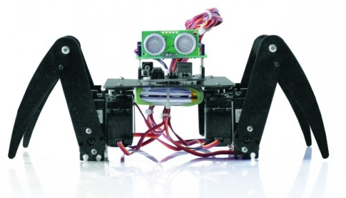
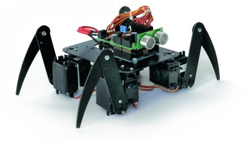
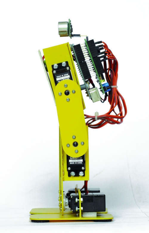
SPIDER ROBOT
With this robot we wanted to replicate the appearance and movements of a spider with all the limitations derived from a simplified mechanics and a limited cost. The choice has been the use of two servos for paw for a total of four legs, which, however, ensure a final result very attractive. The largest number of servos relative to the robot BIPE should not scare because, at the end, this robot is the most simple to make and having regard to the intrinsic stability, does not present serious problems even in the operation. For this robot we have not even provided the adjustment of the neutral servos because of some inaccuracies should not be to influence the operation.The only care is to fix the battery pack in the center so the robots present the center of gravity exactly in the center. During the movement three legs always remain in contact with the ground while one moves, rising, thereby ensuring a good stability.
The mechanical is made by PCB, the same material used for printed electronic and suggest paint it black to improve the aesthetic appearance. No soldering required, and each piece is simply screwed to the servos that make up the mechanics.
How practical advice suggest to program the Arduino board with this program and then electrically connecting the servos, doing so will all be positioned exactly in the middle.Then you connect the mechanical servos in their proper locations.
// SPIDER ARDUINO
// by Segatello Mirco for ElettronicaIN
// Compilato con Arduino21

#include <Servo.h>
#include <IRremote.h>

#define RECV_PIN 10   // pin per sensore IR
#define PING_PIN 11   // pin per sensore RADAR
#define       P1 12   // pin per pulsante

#define STNB_CODE1 0x81D    // Stop Philips TV remote
#define STNB_CODE2 0x1D     // Codice alternativo
#define WALK_CODE1 0x81C    // Play Philips TV remote
#define WALK_CODE2 0x1C     // Codice alternativo
#define SPEEDUP_CODE1 0x820 // Prg+ Philips TV remote
#define SPEEDUP_CODE2 0x20  // Codice alternativo
#define SPEEDDW_CODE1 0x821 // Prg- Philips TV remote
#define SPEEDDW_CODE2 0x21  // Codice alternativo
#define LEFT_CODE1    0x2C  // Left Philips remote
#define LEFT_CODE2    0x82C  // Codice alternativo
#define RIGHT_CODE1    0x2B  // Left Philips remote
#define RIGHT_CODE2    0x82B  // Codice alternativo

#define MODE_OFF       0    // Servi OFF
#define MODE_STANDBY   1    // Servi armati in posizione di riposo
#define MODE_INWALK    2    // Assume la posizione di partenza
#define MODE_WALK      3    // Cammina in avanti
#define MODE_INSTANDBY 4    // Assume la posizione di standby
#define MODE_LEFT      5    // Si gira verso sinistra
#define MODE_RIGHT     6    // Si gira a destra
#define MODE_REVWALK   7    // Cammina all'indietro

IRrecv irrecv(RECV_PIN);
decode_results results;

int RobotMode = MODE_OFF;
int TimeOneStep = 6000;     // Tempo in msec per eseguire un passo completo

Servo servo0, servo1, servo2, servo3,
      servo4, servo5, servo6, servo7;  // oggetti servo

int leg_old[8] = {90, 90, 90, 90, 90, 90, 90, 90}; //posizione precedente dei servi
int leg[8];                 //posizione attuale dei servi
int i;

void setup()
{
  Serial.begin(9600);       // Start seriale
  Serial.println("BIPE Aduino V1.0");
  irrecv.enableIRIn();      // Start ricevitore IR
  irrecv.blink13(true);     // Lampeggio LED in ricezione IR attivo
  pinMode(P1, INPUT);       // Pulsante
  digitalWrite(P1, HIGH);   // Abilita pull-up
  levelBat();               // Verifica stato batteria
  Serial.println("Livello batteria OK.");
  Serial.println("Inizializzo Servi...");
  initServo();              // Inizializza servi
  Serial.println("Servi inizializzati.");
  inStandby();              // Robot in attesa di comando
}

void loop()
{
  if (irrecv.decode(&results)) IRcommand();
  if (RobotMode==MODE_WALK)   walk();
  if (RobotMode==MODE_REVWALK) walkReverse();
  if (RobotMode==MODE_LEFT)   leftWalk();
  if (RobotMode==MODE_RIGHT)   rightWalk();
  levelBat();
  if (RobotMode==MODE_STANDBY) delay(100);
  if (digitalRead(P1)==0) P1Press();

  int obstacle = readDistance();
  Serial.print("Ostacolo: ");
  Serial.println(obstacle, DEC);
  if (obstacle<20)  inStandby();

  // Ricezione seriale per setup servi
  if (Serial.available()) SerialSet();
}

void SerialSet()
{
   // E' arrivato un comando dalla seriale
  byte c;
  byte srv;

  while(Serial.available())     // finchè ci sono dati
  {
      c = Serial.read();    // legge i dati e li salva in una variabile
      if ( 97 <= c <= 102)   Serial.print(c);
 }
}

void IRcommand()
{
    // E' arrivato un comando via IR
    Serial.println(results.value, HEX);  // ECO su serial monitor per sapere il codice arrivato

    if (results.value == WALK_CODE1 || results.value == WALK_CODE2)   inWalk();
    else if (results.value == LEFT_CODE1 || results.value == LEFT_CODE2)  inLeft();
    else if (results.value == RIGHT_CODE1 || results.value == RIGHT_CODE2)  inRight();
    else if (results.value == STNB_CODE1 || results.value == STNB_CODE2)  inStandby();
    else if (results.value == SPEEDUP_CODE1 || results.value == SPEEDUP_CODE2) {
      if (TimeOneStep > 1000) TimeOneStep -= 500; }
    else if (results.value == SPEEDDW_CODE1 || results.value == SPEEDDW_CODE2) {
      if (TimeOneStep < 6000) TimeOneStep += 500; }
    Serial.print("TimeOneStep= ");
    Serial.println(TimeOneStep);
    irrecv.resume(); // Resume decoding
}

void P1Press()
{
  // E' stato premuto il pulsante
  while (digitalRead(P1)==0) delay(100);
  if (RobotMode==MODE_WALK)  inStandby();
  else if (RobotMode==MODE_STANDBY) inWalk();
}

void levelBat()
{
  // controlla livello batteria
  int VbatRAW = analogRead(A0);
  float Vbat = float(VbatRAW)/50;
  Serial.print("Vbat= ");
  Serial.println(Vbat, DEC);
  if (Vbat<6.0)   {
    Serial.println("Livello batteria basso!");
    inOff();
  }
}

void initServo()
{
  // posizione iniziale dei servi
  servo0.attach(2);  // connette servo
  delay(300);
  servo1.attach(3);  // connette servo
  delay(300);
  servo2.attach(4);  // connette servo
  delay(300);
  servo3.attach(5);  // connette servo
  delay(300);
  servo4.attach(6);  // connette servo
  delay(300);
  servo5.attach(7);  // connette servo
  delay(300);
  servo6.attach(8);  // connette servo
  delay(300);
  servo7.attach(9);  // connette servo
  delay(300);
}

void inOff()
{
  // Spegne tutti i servi
  leg[0] = 90;
  leg[1] = 90;
  leg[2] = 90;
  leg[3] = 90;
  leg[4] = 90;
  leg[5] = 90;
  leg[6] = 90;
  leg[7] = 90;
  setServo();
  servo0.detach();  // connette servo
  servo1.detach();  // connette servo
  servo2.detach();  // connette servo
  servo3.detach();  // connette servo
  servo4.detach();  // connette servo
  servo5.detach();  // connette servo
  servo6.detach();  // connette servo
  servo7.detach();  // connette servo
  RobotMode = MODE_OFF;
  // Da questo modalità si deve spegnere il robot e ricaricare le batterie
}

void inStandby()
{
  // Posiziono tutti i servi al centro
  leg[0] = 90;
  leg[1] = 90;
  leg[2] = 90;
  leg[3] = 90;
  leg[4] = 90;
  leg[5] = 90;
  leg[6] = 90;
  leg[7] = 90;
  setServo();
  RobotMode = MODE_STANDBY;
  Serial.println("Sono in Standby...");
}

void inWalk()
{
  // Si alza pronto per partire
  leg[0] = 99;
  leg[1] = 126;
  leg[2] = 117;
  leg[3] = 54;
  leg[4] = 99;
  leg[5] = 126;
  leg[6] = 117;
  leg[7] = 54;
  setServo();
  RobotMode = MODE_WALK;
  Serial.println("Walk Mode...");
}

void setServo()
{
   // Posiziona i servi alle cordinate specificate da leg[]
   for (i=0; i<18; i++) {
       servo0.write(leg_old[0] + i*(leg[0]-leg_old[0])/18);
       servo1.write(leg_old[1] + i*(leg[1]-leg_old[1])/18);
       servo2.write(leg_old[2] + i*(leg[2]-leg_old[2])/18);
       servo3.write(leg_old[3] + i*(leg[3]-leg_old[3])/18);
       servo4.write(leg_old[4] + i*(leg[4]-leg_old[4])/18);
       servo5.write(leg_old[5] + i*(leg[5]-leg_old[5])/18);
       servo6.write(leg_old[6] + i*(leg[6]-leg_old[6])/18);
       servo7.write(leg_old[7] + i*(leg[7]-leg_old[7])/18);
       delay(TimeOneStep/4/18);
    }
    leg_old[0]=leg[0];
    leg_old[1]=leg[1];
    leg_old[2]=leg[2];
    leg_old[3]=leg[3];
    leg_old[4]=leg[4];
    leg_old[5]=leg[5];
    leg_old[6]=leg[6];
    leg_old[7]=leg[7];
}

void setServoWalk()
{
   // Posiziona i servi durante la camminata
   for (i=1; i<=18; i++) {
       servo0.write(leg_old[0] + i*(leg[0]-leg_old[0])/18);
       servo2.write(leg_old[2] + i*(leg[2]-leg_old[2])/18);
       servo4.write(leg_old[4] + i*(leg[4]-leg_old[4])/18);
       servo6.write(leg_old[6] + i*(leg[6]-leg_old[6])/18);

      // servi delle zampe
         if ( i <= 9 )
           servo1.write(leg_old[1] + i*(leg[1]-leg_old[1])/9);
         else
           servo1.write(leg_old[1] + (18-i)*(leg[1]-leg_old[1])/9);

         if ( i <= 9 )
           servo3.write(leg_old[3] + i*(leg[3]-leg_old[3])/9);
         else
           servo3.write(leg_old[3] + (18-i)*(leg[3]-leg_old[3])/9);

         if ( i <= 9 )
           servo5.write(leg_old[5] + i*(leg[5]-leg_old[5])/9);
         else
           servo5.write(leg_old[5] + (18-i)*(leg[5]-leg_old[5])/9);

         if ( i <= 9 )
           servo7.write(leg_old[7] + i*(leg[7]-leg_old[7])/9);
         else
           servo7.write(leg_old[7] + (18-i)*(leg[7]-leg_old[7])/9);

       delay(TimeOneStep/4/18);
    }
    leg_old[0]=leg[0];
    leg_old[1]=126;//leg[1];
    leg_old[2]=leg[2];
    leg_old[3]=54;//leg[3];
    leg_old[4]=leg[4];
    leg_old[5]=126;//leg[5];
    leg_old[6]=leg[6];
    leg_old[7]=54; //leg[7];
    if (digitalRead(P1)==0) P1Press();
    if (irrecv.decode(&results)) IRcommand();
}

void walk()
{
      // Coordinate per eseguire un passo

      //passo 1
      leg[0] = 117;
      leg[1] = 126;
      leg[2] = 63;
      leg[3] = 90;   //posizione zampa alzata
      leg[4] = 81;
      leg[5] = 126;
      leg[6] = 99;
      leg[7] = 54;
      setServoWalk();
      if (RobotMode!=MODE_WALK) return;

      //passo 2
      leg[0] = 63;
      leg[1] = 90;   // posizione zampa alzata
      leg[2] = 81;
      leg[3] = 54;
      leg[4] = 63;
      leg[5] = 126;
      leg[6] = 81;
      leg[7] = 54;
      setServoWalk();
      if (RobotMode!=MODE_WALK) return;

      //passo 3
      leg[0] = 81;
      leg[1] = 126;
      leg[2] = 99;
      leg[3] = 54;
      leg[4] = 117;
      leg[5] = 90;    // posizione zampa alzata
      leg[6] = 63;
      leg[7] = 54;
      setServoWalk();
      if (RobotMode!=MODE_WALK) return;

      //passo 4
      leg[0] = 99;
      leg[1] = 126;
      leg[2] = 117;
      leg[3] = 54;
      leg[4] = 99;
      leg[5] = 126;
      leg[6] = 117;
      leg[7] = 90;    // posizione zampa alzata
      setServoWalk();
}

void walkReverse()
{
      //passo 1
      leg[0] = 63;
      leg[1] = 126;
      leg[2] = 117;
      leg[3] = 90;  // si alza
      leg[4] = 99;
      leg[5] = 126;
      leg[6] = 81;
      leg[7] = 54;
      setServoWalk();
      if (RobotMode!=MODE_WALK) return;

      //passo 2
      leg[0] = 117;
      leg[1] = 126;
      leg[2] = 99;
      leg[3] = 54;
      leg[4] = 117;
      leg[5] = 90;  // si alza
      leg[6] = 99;
      leg[7] = 54;
      setServoWalk();
      if (RobotMode!=MODE_WALK) return;

      //passo 3
      leg[0] = 99;
      leg[1] = 126;
      leg[2] = 81;
      leg[3] = 54;
      leg[4] = 63;
      leg[5] = 126;
      leg[6] = 117;
      leg[7] = 90;  // si alza
      setServoWalk();
      if (RobotMode!=MODE_WALK) return;

      //passo 4
      leg[0] = 81;
      leg[1] = 90; // si alza
      leg[2] = 63;
      leg[3] = 54;
      leg[4] = 81;
      leg[5] = 126;
      leg[6] = 63;
      leg[7] = 54;
      setServoWalk();
}

void inLeft()
{
  // Si alza pronto per girare a sinistra
  leg[0] = 63;
  leg[1] = 126;
  leg[2] = 81;
  leg[3] = 54;
  leg[4] = 99;
  leg[5] = 126;
  leg[6] = 117;
  leg[7] = 54;
  setServo();
  RobotMode = MODE_LEFT;
  Serial.println("Left Mode...");
}

void leftWalk()
{
      //passo 1
      leg[0] = 81;
      leg[1] = 126;
      leg[2] = 99;
      leg[3] = 54;
      leg[4] = 117;
      leg[5] = 126;
      leg[6] = 63;
      leg[7] = 90;//*
      setServoWalk();
      if (RobotMode!=MODE_LEFT) return;

      //passo 2
      leg[0] = 99;
      leg[1] = 126;
      leg[2] = 117;
      leg[3] = 54;
      leg[4] = 63;
      leg[5] = 90;//*
      leg[6] = 99;
      leg[7] = 54;
      setServoWalk();
      if (RobotMode!=MODE_LEFT) return;

      //passo 3
      leg[0] = 117;
      leg[1] = 126;
      leg[2] = 63;
      leg[3] = 90;//*
      leg[4] = 81;
      leg[5] = 126;
      leg[6] = 99;
      leg[7] = 54;
      setServoWalk();
      if (RobotMode!=MODE_LEFT) return;

      //passo 4
      leg[0] = 63;
      leg[1] = 90;//*
      leg[2] = 81;
      leg[3] = 54;
      leg[4] = 99;
      leg[5] = 126;
      leg[6] = 117;
      leg[7] = 54;
      setServoWalk();
}

void inRight()
{
  // Si alza pronto per girare a destra
  leg[0] = 99;
  leg[1] = 126;
  leg[2] = 117;
  leg[3] = 54;
  leg[4] = 63;
  leg[5] = 126;
  leg[6] = 81;
  leg[7] = 54;
  setServo();
  RobotMode = MODE_RIGHT;
  Serial.println("Right Mode...");
}

void rightWalk()
{
      //passo 1
      leg[0] = 81;
      leg[1] = 126;
      leg[2] = 99;
      leg[3] = 54;
      leg[4] = 117;
      leg[5] = 90;//*
      leg[6] = 63;
      leg[7] = 54;
      setServoWalk();
      if (RobotMode!=MODE_RIGHT) return;

      //passo 2
      leg[0] = 63;
      leg[1] = 126;
      leg[2] = 81;
      leg[3] = 54;
      leg[4] = 99;
      leg[5] = 126;
      leg[6] = 117;
      leg[7] = 90;//*
      setServoWalk();
      if (RobotMode!=MODE_RIGHT) return;

      //passo 3
      leg[0] = 117;
      leg[1] = 90;//*
      leg[2] = 63;
      leg[3] = 54;
      leg[4] = 81;
      leg[5] = 126;
      leg[6] = 99;
      leg[7] = 54;
      setServoWalk();
      if (RobotMode!=MODE_RIGHT) return;

      //passo 4
      leg[0] = 99;
      leg[1] = 126;
      leg[2] = 117;
      leg[3] = 90;//*
      leg[4] = 63;
      leg[5] = 126;
      leg[6] = 81;
      leg[7] = 54;
      setServoWalk();
}

long readDistance()
{
  // Procedura per leggere la presenza di ostacoli
  // Viene generato un PING di 2usec ed atteso l'ECO di risposta
  long duration, cm;
  pinMode(PING_PIN, OUTPUT);
  digitalWrite(PING_PIN, LOW);
  delayMicroseconds(2);
  digitalWrite(PING_PIN, HIGH);
  delayMicroseconds(5);
  digitalWrite(PING_PIN, LOW);

  // Lo stesso pin che genera il trigger è usato per la lettura
  // del segnale di ritorno
  pinMode(PING_PIN, INPUT);
  duration = pulseIn(PING_PIN, HIGH);

  // ritorna distanza ostacolo in cm
  return duration / 29 / 2;
}
Make sure that the servos are aligned and that the legs are neither too open nor too closed, taking as reference the pictures posted here .

Connect the servos to the robot Spider
| Servo |
Arduino Pin |
Connector shield |
Function |
| Servo 0 |
2 |
S1 |
Angle right foreleg |
| Servo 1 |
3 |
S2 |
Elevation of right foreleg |
| Servo 2 |
4 |
S3 |
Angle of the right hind leg |
| Servo 3 |
5 |
S4 |
Elevation of the right hind leg |
| Servo 4 |
6 |
S5 |
Angle left hind leg |
| Servo 5 |
7 |
S6 |
Elevation of the left hind paw |
| Servo 6 |
8 |
S7 |
Angle left foreleg |
| Servo 7 |
9 |
S8 |
Elevation of left foreleg |
Turning on after 1 second (after the warm-up switching power supply) all the servos will be placed in the neutral point. It may happen that some servos vibrate slightly, this is due to the internal mechanism that has yet to find the center point, sometimes just a small blow to the servant to fix things.
For this robot we never anticipated that you can edit parameters, movements are many and complex and there are too many variables to set, we preferred to find a setup that could offer the best performance in every situation. For our prototype LiPo battery that powers it has been established under the structure, right through to the servos, ensuring, in addition to the centering of weight, a low center of gravity.
Let us see now the analysis of the firmware describing those functions that are common to all the robots such as the procedure that reads the distance from obstacles by means of the sensor SRF05:
Code 6
long readDistance()
{
  long duration, cm;
  pinMode(PING_PIN, OUTPUT);
  digitalWrite(PING_PIN, LOW);
  delayMicroseconds(2);
  digitalWrite(PING_PIN, HIGH);
  delayMicroseconds(5);
  digitalWrite(PING_PIN, LOW);
  pinMode(PING_PIN, INPUT);
  duration = pulseIn(PING_PIN, HIGH);
  // ritorna distanza ostacolo in cm
  return duration / 29 / 2;
}
The procedure foresees to send a pulse duration of 2usec to the sensor, which, proceeds generating a series of ultrasound to the outside. The same pin is subsequently used as input for reading, via the function PulseIn, the time taken by the sound to reach the obstacle, bounce and return to the sensor, the period during which the sensor maintains a high level of the line. The time taken by the ultrasound to go and return to the sensor is proportional to the distance of the object.
Here also the procedure for reading the voltage on the battery:
Code 7
void levelBat()
{
  int VbatRAW = analogRead(A0);
  float Vbat = float(VbatRAW)/50;
  Serial.print("Vbat= ");
  Serial.println(Vbat, DEC);
  if (Vbat<6.0)   {
    Serial.println("Livello batteria basso!");
    inOff();
  }
}
The procedure is simple, plan to read the analog channel A0 of Arduino and save the result into a variable VbatRAW. As explained above, by dividing this value by 50, is obtained by the voltage in volts of the battery. Since excessively discharge the battery can damage it, we expected an alarm to the level below which the robot is immediately stopped and all the servos are disabled. The threshold value is defined in 6.0 V ideal for use with a battery pack consisting of two cell LiPo or six if you use NiMh or NiCd cells, eight cells used instead if you can increase this value up to 8.0 volts or, one volt per used cell.
Another common procedure is called to all the robots initServo () to initialize the servos:
Code 8
void initServo()
{
  // posizione iniziale dei servi
  servo0.attach(2);  // connette servo
  delay(300);
........
  servo7.attach(9);  // connette servo
  delay(300);
}
The function Servo.attach() associates each object provides the respective servo output, from this moment the servant reaches the PWM signal.
The procedure inOff () performs the opposite function by removing the pin from their association with the servos and leaving them with no control.
Code 9
void inOff()
{
  leg[0] = 90;
.....
  leg[7] = 90;
  setServo();
  servo0.detach();  // connette servo
....
  servo7.detach();  // connette servo
  RobotMode = MODE_OFF;
}
The function to put in sleep mode the robot is called Standby() and simply place all the servos in the central position. In the case of the robot Filippo and BIPE the servos are positioned in their respective neutral points whose values are contained in the vector named leg_ntr [].
Code 10
void inStandby()
{
  leg[0] = 90;
....
  leg[7] = 90;
  setServo();
  RobotMode = MODE_STANDBY;
  Serial.println("Sono in Standby...");
}
A very important procedure is to ensure that the servos have to place to desired coordinates:
Code 11
void setServo()
{
   for (i=0; i<18; i++) {
       servo0.write(leg_old[0] + i*(leg[0]-leg_old[0])/18);
       servo1.write(leg_old[1] + i*(leg[1]-leg_old[1])/18);
       servo2.write(leg_old[2] + i*(leg[2]-leg_old[2])/18);
       servo3.write(leg_old[3] + i*(leg[3]-leg_old[3])/18);
       servo4.write(leg_old[4] + i*(leg[4]-leg_old[4])/18);
       servo5.write(leg_old[5] + i*(leg[5]-leg_old[5])/18);
       servo6.write(leg_old[6] + i*(leg[6]-leg_old[6])/18);
       servo7.write(leg_old[7] + i*(leg[7]-leg_old[7])/18);
       delay(TimeOneStep/4/18);
    }
    leg_old[0]=leg[0];
    leg_old[1]=leg[1];
    leg_old[2]=leg[2];
    leg_old[3]=leg[3];
    leg_old[4]=leg[4];
    leg_old[5]=leg[5];
    leg_old[6]=leg[6];
    leg_old[7]=leg[7];
}
If we set directly the servo, it was a sudden movement and the robot would move in spurts. He prefers, instead, gradually controlling the servo to bring it to the desired position in a defined time. To do this you must define a vector leg[] that contains the coordinates to be achieved by each servo and a vector leg_old[] that contains the actual coordinates. The procedure controls the servos by sending them all coordinated by the intermediate value at the target value in a time defined by the variable TimeOneStep. This system allows us to obtain fluid movements.
Only the robot spider there is a procedure called setServoWalk() because it is necessary that some servos are moving at different speeds than the other. During the walk the three legs in contact with the floor moving slowly, the fourth foot must lift and move fast in the opposite direction to progress.
Download
-->-->-->-->-->-->
-->-->


