Tutorial – Arduino and SIM900 GSM Modules
Use the SIM900 GSM modules with Arduino in Chapter 55 of our Arduino Tutorials. The first chapter is here, the complete series is detailed here. Updated 14/02/2014
Introduction
The goal of this tutorial is to illustrate various methods of interaction between an Arduino Uno (or compatible) and the GSM cellular network using a SIM900 GSM shield, with which you can then use your existing knowledge to build upon those methods. Updated 08/01/2014.
Apart from setting up the shield we’ll examine:
- Making a telephone call from your Arduino
- Sending an SMS text message
- Receiving text messages with the shield and displaying them on the serial monitor
- Simple controlling of the host Arduino by calling it from another telephone
- Controlling the Arduino via SMS text message
We’ll be using a SIMCOM SIM900 GSM module shield. (If you’re looking for tutorials on the Spreadtrum SM5100 modules, start here). There must be scores of Arduino shields or modules using the SIM900, so as you can imagine each one may be a little bit different with regards to the hardware side of things – so we’re assuming you have an understanding of how hardware and software serial works as well as supply voltages and the hardware side of the Arduino world.
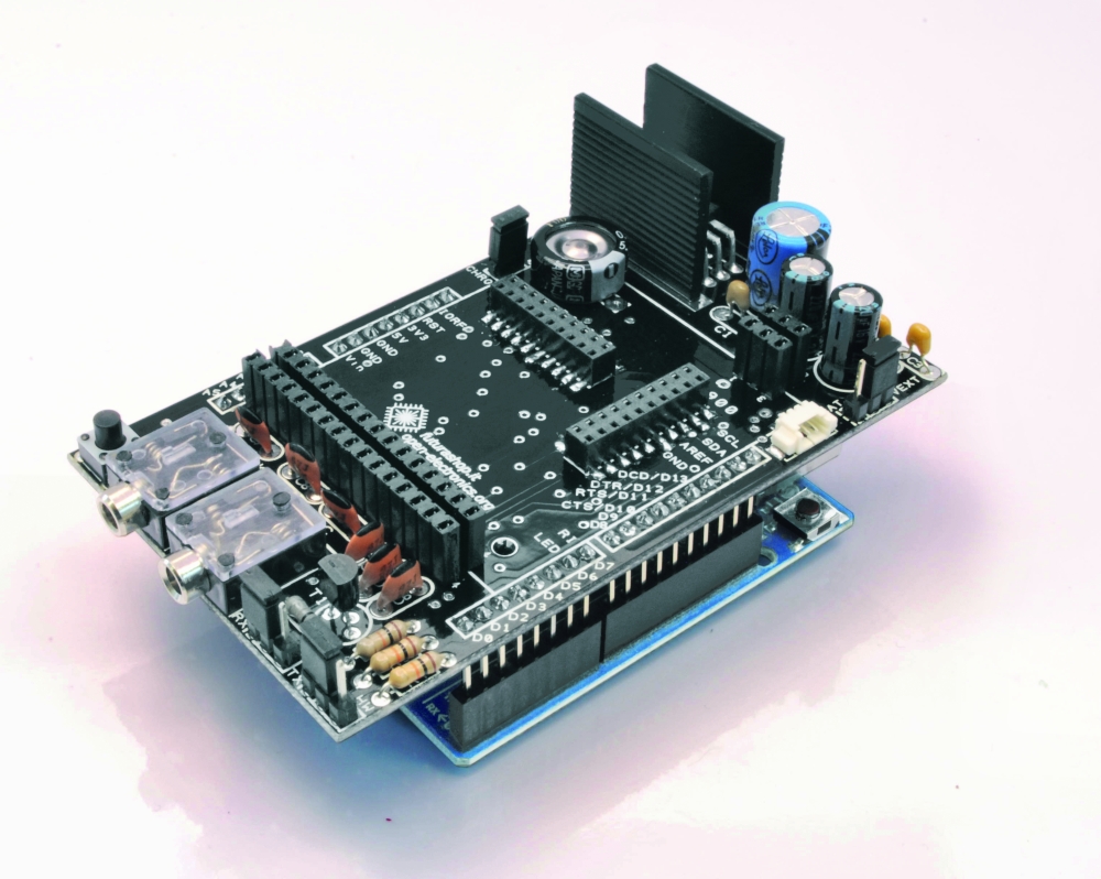
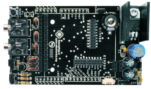
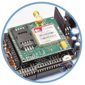
As for the specific shield to use, we just chose the cheapest one available at the time – which turned out to be the “SIM900 GPRS/GSM Arduino shield” from tronixlabs.com:
![]()
However with a little research and work on your part, the sketches provided should also work with any SIM900 module/shield and Arduino – as long as you have the appropriate serial and power settings.
Getting Started
A little preparation goes a long way, so make sure you’ve covered the following points:
- Regarding your cellular provider. Do you have coverage on a GSM 850 MHz, GSM 900 MHz, DCS 1800 MHz or PCS 1900 MHz network? When we say GSM that means 2G – not 3G, 4G or LTE. Will they allow the use of non-supported devices on the network? Some carriers will block IMEI numbers that were not provided by their sales channel. Or you may have to call the provider and supply the IMEI of your GSM module to allow it on the network. Finally, it would be wise to use either a prepaid or an account that offers unlimited SMS text messaging – you don’t want any large bills if things go wrong.
- Power. Do you have adequate power for your SIM900 module? Some shields will use more current than the Arduino can supply (up to 2A), so you may need an external high-current supply. The Linksprite shield we use needs 5V up to 2A into the onboard DC socket. Otherwise, check with your supplier.
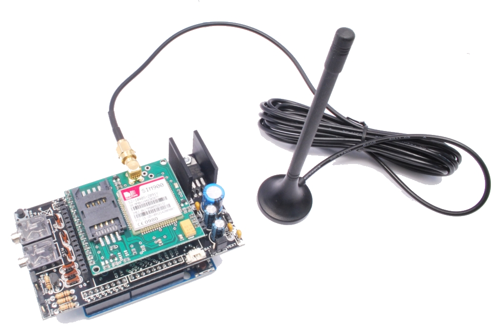
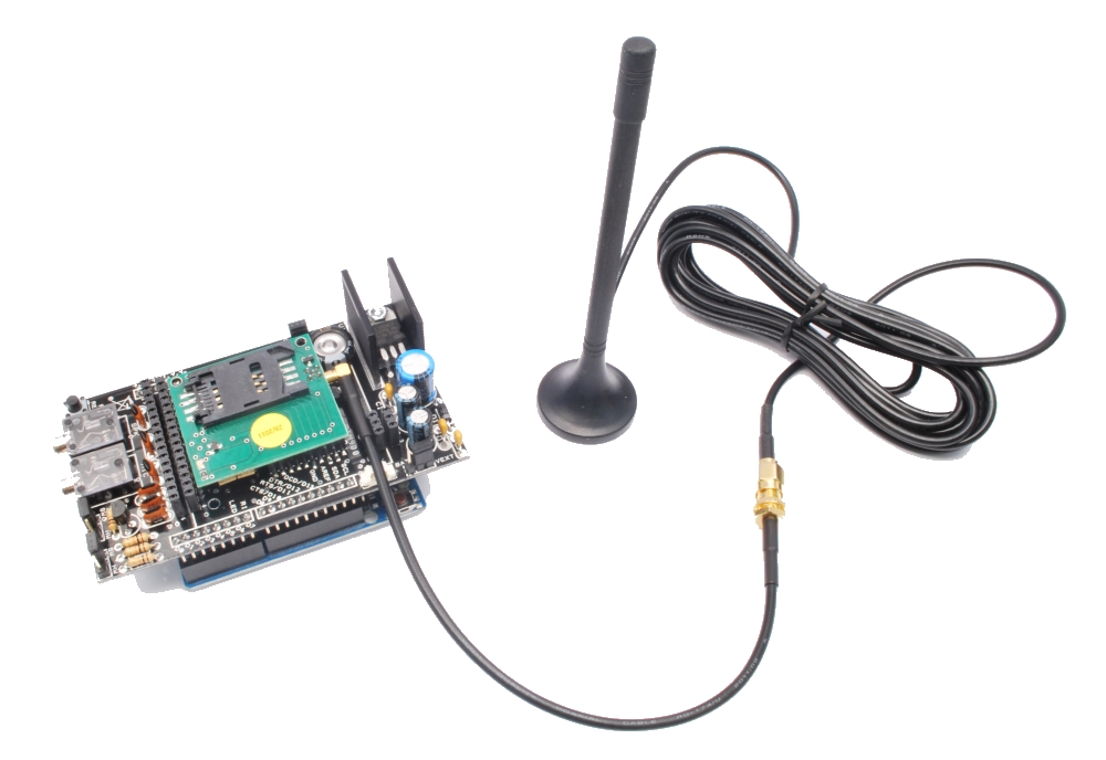
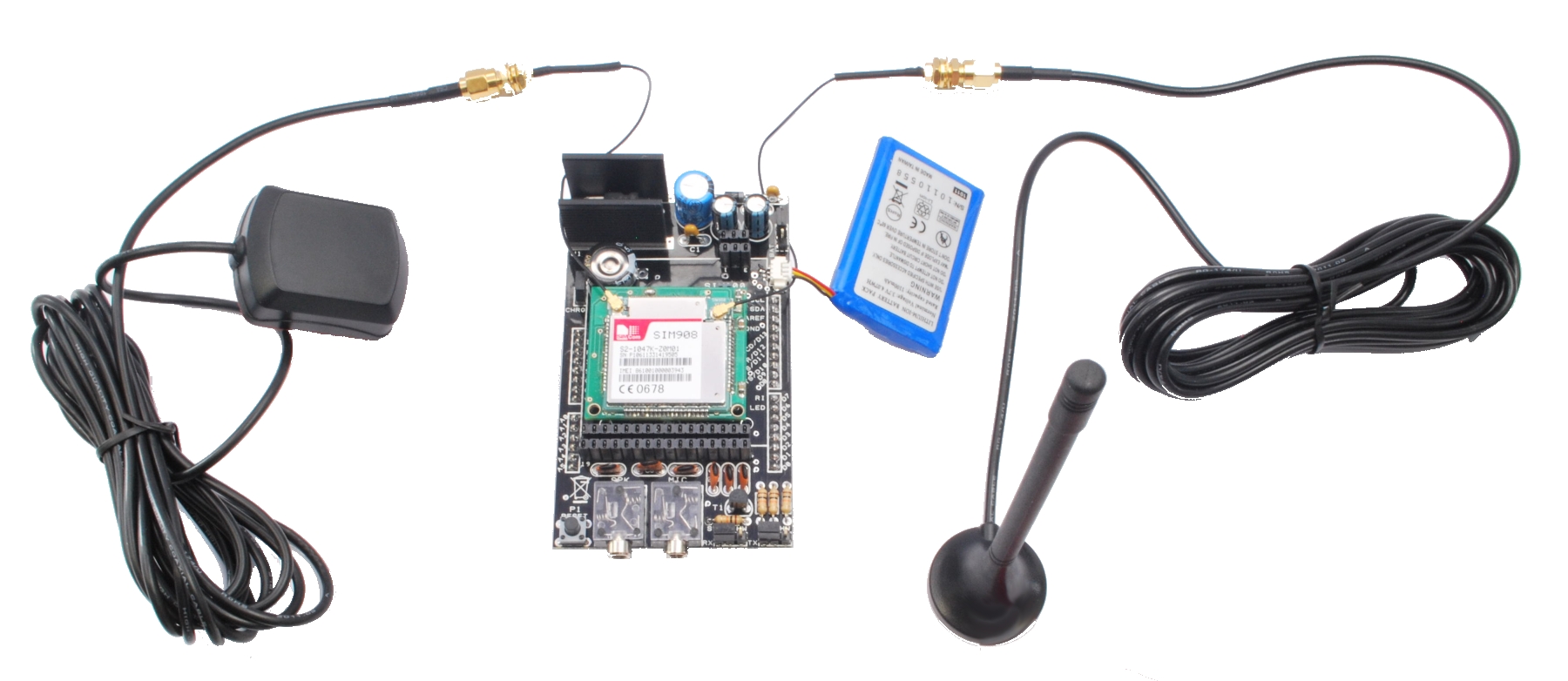
- Antenna. If your module/shield etc. doesn’t have an antenna – get one. You do need it.
- Turn off the PIN lock on the SIM card. The easiest way to do this is to put the SIM in a handset and use the menu function.
- And as always, please don’t make an auto-dialler…

Furthermore, download the SIM900 hardware manual (.pdf) and the AT command manual (.pdf), as we’ll refer to those throughout the tutorial.
Power
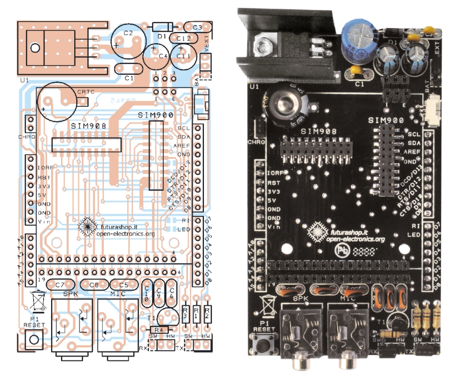
There is a DC socket on the shield, which is for a 5V power supply:
![]()
Although the data from Linksprite claims the shield will use no more than 450 mA, the SIMCOM hardware manual (page 22) for the module notes that it can draw up to 2A for short bursts. So get yourself a 5V 2A power supply and connect it via the DC socket, and also ensure the switch next to the socket is set to “EXT”.
Furthermore, you can turn the GSM module on and off with the power button on the side of the shield, and it defaults to off during an initial power-up. Therefore you’ll need to set D9 to HIGH for one second in your sketch to turn the module on (or off if required for power-saving). Don’t panic, we’ll show how this is done in the sketches below.
Software Serial
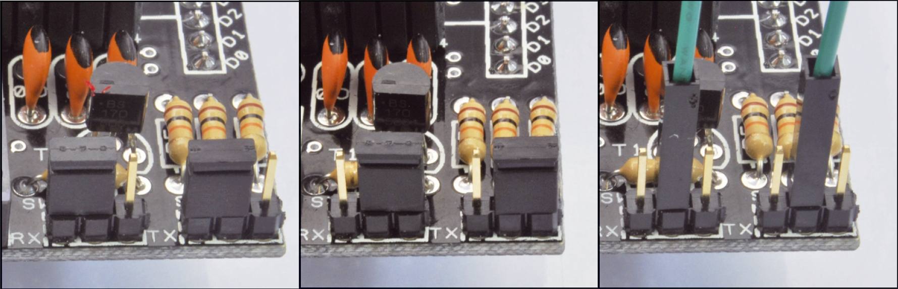
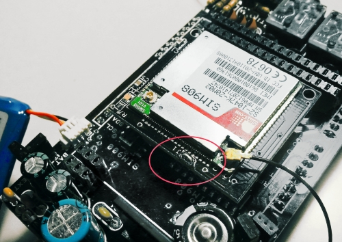
We will use the Arduino software serial library in this tutorial, and the Linksprite shield has hard-wired the serial from the SIM900 to a set of jumpers, and uses a default speed of 19200. Make sure you your jumpers are set to the “SWserial” side, as shown below:
![]()
And thus whenever an instance of SoftwareSerial is created, we use 7,8 as shown below:
SoftwareSerial SIM900(7, 8); // RX, TX
If you shield is different, you’ll need to change the TX and RX pin numbers. This also means you can’t use an Arduino Leonardo or Mega (easily). Finally – note this for later – if your shield is having problems sending data back to your Arduino you may need to edit the SoftwareSerial library – read this for more information.
Wow – all those rules and warnings?
The sections above may sound a little authoritarian, however we want your project to be a success. Now, let’s get started…
A quick test…
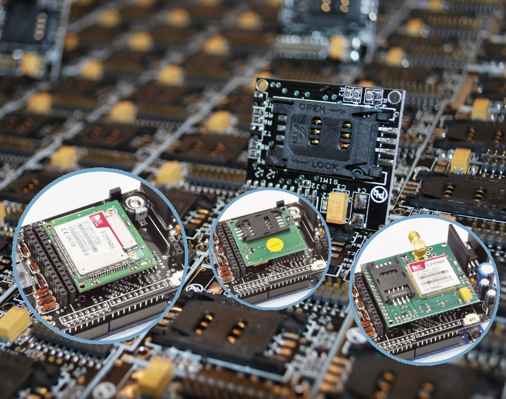
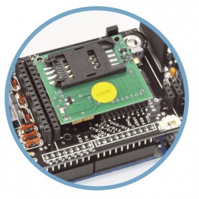
At this point we’ll check to make sure your shield and locate and connect to the cellular network. So make sure your SIM card is active with your cellular provider, the PIN lock is off, and then insert it and lock the SIM card to the carrier on the bottom of the shield:
![]()
Then plug the shield into your Uno, attach 5V power to the DC socked on the GSM shield, and USB from the Uno to the PC. Press the “PWRKEY” button on the side of the shield for a second, then watch the following two LEDs:
![]()
The bright “STATUS” LED will come on, and then the “NETLIGHT” LED will blink once every 800 milliseconds- until the GSM module has found the network, at which point it will blink once every three seconds. This is shown in the following video:
Nothing can happen until that magic three-second blink – so if that doesn’t appear after a minute, something is wrong. Check your shield has the appropriate power supply, the antenna is connected correctly, the SIM card is seated properly and locked in- and that your cellular account is in order. Finally, you may not have reception in that particular area, so check using a phone on the same network or move to a different location.
Making a telephone call from your Arduino
You can have your Arduino call a telephone number, wait a moment – then hang up. This is an inexpensive way of alerting you of and consider the following sketch:
// Example 55.1

#include <SoftwareSerial.h>
SoftwareSerial SIM900(7, 8); // configure software serial port

void setup()
{
  SIM900.begin(19200);
  SIM900power();
  delay(20000);  // give time to log on to network.
}

void SIM900power()
// software equivalent of pressing the GSM shield "power" button
{
  digitalWrite(9, HIGH);
  delay(1000);
  digitalWrite(9, LOW);
  delay(5000);
}

void callSomeone()
{
  SIM900.println("ATD + +12128675309;"); // dial US (212) 8675309
  delay(100);
  SIM900.println();
  delay(30000);            // wait for 30 seconds...
  SIM900.println("ATH");   // hang up
}

void loop()
{
  callSomeone(); // call someone
  SIM900power();   // power off GSM shield
  do {} while (1); // do nothing
}
The sketch first creates a software serial port, then in void setup() starts the software serial port, and also turns on the GSM shield with the function SIM900power (which simply sets D9 high for a second which is the equivalent of pressing the power button). Notice the delay function in void setup – this gives the GSM module a period of time to locate and log on to the cellular network. You may need to increase (or be able to decrease) the delay value depending on your particular situation. If in doubt, leave it as a long period.
The process of actually making the call is in the function callSomeone(). It sends a string of text to the GSM module which consists of an AT command. These are considered the “language” for modems and thus used for various tasks. We use the ATD command to dial (AT… D for dial) a number. The number as you can see in the sketch needs to be in world-format. So that’s a “+” then the country code, then the phone number with area code (without the preceding zero).
So if your number to call is Australia (02) 92679111 you would enter +61292679111. Etcetera. A carriage return is then sent to finalise the command and off it goes dialling the number. Here’s a quick video demonstration for the non-believers:
After thirty seconds we instruct the module to hand up with another AT command – “ATH” (AT… H for “hang up”), followed by turning off the power to the module. By separating the call feature into a function – you can now insert this into a sketch (plus the preceding setup code) to call a number when required.
Sending an SMS text message
This is a great way of getting data from your Arduino to almost any mobile phone in the world, at a very low cost. For reference, the maximum length of an SMS text message is 160 characters – however you can still say a lot with that size limit. First we’ll demonstrate sending an arbitrary SMS. Consider the following sketch:
// Example 55.2

#include <SoftwareSerial.h>
SoftwareSerial SIM900(7, 8);

void setup()
{
  SIM900.begin(19200);
  SIM900power();
  delay(20000);  // give time to log on to network.
}

void SIM900power()
// software equivalent of pressing the GSM shield "power" button
{
  digitalWrite(9, HIGH);
  delay(1000);
  digitalWrite(9, LOW);
  delay(5000);
}

void sendSMS()
{
  SIM900.print("AT+CMGF=1\r");                                                        // AT command to send SMS message
  delay(100);
  SIM900.println("AT + CMGS = \"+12128675309\"");                                     // recipient's mobile number, in international format
  delay(100);
  SIM900.println("Hello, world. This is a text message from an Arduino Uno.");        // message to send
  delay(100);
  SIM900.println((char)26);                       // End AT command with a ^Z, ASCII code 26
  delay(100);
  SIM900.println();
  delay(5000);                                     // give module time to send SMS
  SIM900power();                                   // turn off module
}

void loop()
{
  sendSMS();
  do {} while (1);
}
The basic structure and setup functions of the sketch are the same as the previous example, however the difference here is the function sendSMS(). It used the AT command “AT+CMGF” to tell the GSM module we want to send an SMS in text form, and then “AT+CMGS” followed by the recipient’s number. Once again note the number is in international format. After sending the send SMS commands, the module needs five seconds to do this before we can switch it off. And now for our ubiquitous demonstration video:
You can also send text messages that are comprised of numerical data and so on – by compiling the required text and data into a string, and then sending that. Doing so gives you a method to send such information as sensor data or other parameters by text message.
For example, you might want to send daily temperature reports or hourly water tank levels. For our example, we’ll demonstrate how to send a couple of random numbers and some text as an SMS. You can then use this as a framework for your own requirements. Consider the following sketch:
// Example 55.3

#include <SoftwareSerial.h>
SoftwareSerial SIM900(7, 8);
int x,y;
String textForSMS;

void setup()
{
  SIM900.begin(19200);
  SIM900power();
  delay(20000);  // give time to log on to network.
  randomSeed(analogRead(0));
}

void SIM900power()
// software equivalent of pressing the GSM shield "power" button
{
  digitalWrite(9, HIGH);
  delay(1000);
  digitalWrite(9, LOW);
  delay(7000);
}

void sendSMS(String message)
{
  SIM900.print("AT+CMGF=1\r");                     // AT command to send SMS message
  delay(100);
  SIM900.println("AT + CMGS = \"+12128675309\"");  // recipient's mobile number, in international format
  delay(100);
  SIM900.println(message);                         // message to send
  delay(100);
  SIM900.println((char)26);                        // End AT command with a ^Z, ASCII code 26
  delay(100);
  SIM900.println();
  delay(5000);                                     // give module time to send SMS
  SIM900power();                                   // turn off module
}

void loop()
{
  x = random(0,255);
  y = random(0,255);
  textForSMS = "Your random numbers are ";
  textForSMS.concat(x);
  textForSMS = textForSMS + " and ";
  textForSMS.concat(y);
  textForSMS = textForSMS + ". Enjoy!";
  sendSMS(textForSMS);
  do {} while (1);
}
Take note of the changes to the function sendSMS(). It now has a parameter – message, which is a String which contains the text to send as an SMS. In void loop() the string variable textForSMS is constructed. First it contains some text, then the values for x and y are added with some more text. Finally the string is passed to be sent as an SMS. And here it is in action:
Receiving text messages and displaying them on the serial monitor
Now let’s examine receiving text messages. All we need is to send two AT commands inside void setup() and then repeat every character sent from the shield to the serial monitor. The first command to use is AT+CMGF=1 which sets the SMS mode to text (as used in the previous example) and the second is AT+CNMI=2,2,0,0 – which tells the GSM module to send the contents of any new SMS out to the serial line. To demonstrate this, set up your hardware as before, upload the following sketch:
// Example 55.4

#include <SoftwareSerial.h>
SoftwareSerial SIM900(7, 8);

char incoming_char=0;

void setup()
{
  Serial.begin(19200); // for serial monitor
  SIM900.begin(19200); // for GSM shield
  SIM900power();  // turn on shield
  delay(20000);  // give time to log on to network.

  SIM900.print("AT+CMGF=1\r");  // set SMS mode to text
  delay(100);
  SIM900.print("AT+CNMI=2,2,0,0,0\r");
  // blurt out contents of new SMS upon receipt to the GSM shield's serial out
  delay(100);
}

void SIM900power()
// software equivalent of pressing the GSM shield "power" button
{
  digitalWrite(9, HIGH);
  delay(1000);
  digitalWrite(9, LOW);
  delay(7000);
}

void loop()
{
  // Now we simply display any text that the GSM shield sends out on the serial monitor
  if(SIM900.available() >0)
  {
    incoming_char=SIM900.read(); //Get the character from the cellular serial port.
    Serial.print(incoming_char); //Print the incoming character to the terminal.
  }
}
… then open the serial monitor, check it’s set to 19200 bps and wait around thirty seconds. You will see some odd characters, then the “OK” responses from the GSM module. Now send a text message to the shield – the time/date stamp, sender and message will appear, for example:
![]()
To preserve my sanity the number used in the demonstrations will be blanked out.
Simple controlling of the host Arduino by calling it from another telephone
When we call our shield from another telephone, it sends the text “RING” out to serial, then “NO CARRIER” when you hang up – which can be harnessed to create a simple dial-in remote control. Use the sketch from the previous example to test this – for example:
![]()
You can also display the number calling in by using the AT command AT+CLIP=1. To do this, just add the following lines to void setup() in the previous sketch:
SIM900.print("AT+CLIP=1\r"); // turn on caller ID notification
delay(100);
Now when a call is received, the caller’s number appears as well – for example:
![]()
Note that the caller ID data for incoming calls isn’t in the international format as it was with SMSs. This will vary depending on your country, so check it out for yourself.
So how can we control the Arduino by calling in? By counting the number of times the shield sends “RING” to the Arduino (just as we did with the other GSM shield). To do this we simply count the number of times the word “RING” comes in from the shield, and then after the third ring – the Arduino will do something.
For our example we have two LEDs connected (via 560Ω resistors) to D12 and D13. When we call the shield and let it ring three times, they will alternate between on and off. Enter and upload the following sketch:
// Example 55.5

#include <SoftwareSerial.h>
char inchar; // Will hold the incoming character from the GSM shield
SoftwareSerial SIM900(7, 8);

int numring=0;
int comring=3;
int onoff=0; // 0 = off, 1 = on

void setup()
{
  Serial.begin(19200);
  // set up the digital pins to control
  pinMode(12, OUTPUT);
  pinMode(13, OUTPUT); // LEDs - off = red, on = green
  digitalWrite(12, HIGH);
  digitalWrite(13, LOW);

  // wake up the GSM shield
  SIM900power();
  SIM900.begin(19200);
  SIM900.print("AT+CLIP=1\r"); // turn on caller ID notification
  delay(100);
}

void SIM900power()
// software equivalent of pressing the GSM shield "power" button
{
  digitalWrite(9, HIGH);
  delay(1000);
  digitalWrite(9, LOW);
  delay(7000);
}

void doSomething()
{
  if (onoff==0)
  {
    onoff=1;
    digitalWrite(12, HIGH);
    digitalWrite(13, LOW);
    Serial.println("D12 high D13 low");
  }
  else
    if (onoff==1)
    {
      onoff=0;
      digitalWrite(12, LOW);
      digitalWrite(13, HIGH);
      Serial.println("D12 low D13 high");
    }
}

void loop()
{
  if(SIM900.available() >0)
  {
    inchar=SIM900.read();
    if (inchar=='R')
    {
      delay(10);
      inchar=SIM900.read();
      if (inchar=='I')
      {
        delay(10);
        inchar=SIM900.read();
        if (inchar=='N')
        {
          delay(10);
          inchar=SIM900.read();
          if (inchar=='G')
          {
            delay(10);
            // So the phone (our GSM shield) has 'rung' once, i.e. if it were a real phone
            // it would have sounded 'ring-ring' or 'blurrrrr' or whatever one cycle of your ring tone is
            numring++;
            Serial.println("ring!");
            if (numring==comring)
            {
              numring=0; // reset ring counter
              doSomething();
            }
          }
        }
      }
    }
  }
}
You can change the number of rings before action with the variable comring, and the action to take is in the function void doSomething(). Finally you can watch a short video of this in action.
We can also modify this system so it only allows control by callers from one number – as long as caller ID works on your system (well it should… it’s 2014 not 1996). So in the next example the system will only call the function doSomething if the call is from a certain number. The sketch works in the same manner as last time – but instead of counting the word “RING”, it will compare the incoming caller’s ID number against one in the sketch.
It may look a little clunky, but it works. In the following example sketch, the number is 2128675309 – so just change the digits to check in void loop():
// Example 55.6

#include <SoftwareSerial.h>
char inchar; // Will hold the incoming character from the GSM shield
SoftwareSerial SIM900(7, 8);

int onoff=0; // 0 = off, 1 = on

void setup()
{
  Serial.begin(19200);
  // set up the digital pins to control
  pinMode(12, OUTPUT);
  pinMode(13, OUTPUT); // LEDs - off = red, on = green
  digitalWrite(12, HIGH);
  digitalWrite(13, LOW);

  // wake up the GSM shield
  SIM900power();
  SIM900.begin(19200);
  delay(20000);  // give time to log on to network.
  SIM900.print("AT+CLIP=1\r"); // turn on caller ID notification
  delay(100);
}

void SIM900power()
// software equivalent of pressing the GSM shield "power" button
{
  digitalWrite(9, HIGH);
  delay(1000);
  digitalWrite(9, LOW);
  delay(7000);
}

void doSomething()
{
  if (onoff==0)
  {
    onoff=1;
    digitalWrite(12, HIGH);
    digitalWrite(13, LOW);
    Serial.println("D12 high D13 low");
  }
  else
    if (onoff==1)
    {
      onoff=0;
      digitalWrite(12, LOW);
      digitalWrite(13, HIGH);
      Serial.println("D12 low D13 high");
    }
}

void loop()
{
  if(SIM900.available() >0)
  {
    inchar=SIM900.read();
    if (inchar=='2')
    {
      delay(10);
      inchar=SIM900.read();
      if (inchar=='1')
      {
        delay(10);
        inchar=SIM900.read();
        if (inchar=='2')
        {
          delay(10);
          inchar=SIM900.read();
          if (inchar=='8')
          {
            delay(10);
            inchar=SIM900.read();
            if (inchar=='6')
            {
              delay(10);
              inchar=SIM900.read();
              if (inchar=='7')
              {
                delay(10);
                inchar=SIM900.read();
                if (inchar=='5')
                {
                  delay(10);
                  inchar=SIM900.read();
                  if (inchar=='3')
                  {
                    delay(10);
                    inchar=SIM900.read();
                    if (inchar=='0')
                    {
                      delay(10);
                      inchar=SIM900.read();
                      if (inchar=='9')
                      {
                        Serial.println("do sometehing");
                        delay(10);
                        // now the number is matched, do something
                        doSomething();
                        // arbitrary delay so the function isn't called again on the same phone call
                        delay(60000);
                      }
                    }
                  }
                }
              }
            }
          }
        }
      }
    }
  }
}
The large delay after calling doSomething() exists to stop the same action being called twice (or more) on the same inbound call. Anyhow, you should now have a grasp on interrogating the data from the shield. Which leads us to the final section…
Controlling the Arduino via SMS text message
As you did with the caller ID data, you can also control the Arduino via SMS fairly easily, and have more options. In our example we’ll explain how to control four digital output pins via SMS. The example works in two stages. First it will wait for an SMS to be received, and then have the contents sent to the Arduino via serial just as we did earlier with the example 55.4. The next stage is to filter out the commands in the text message as we did with example 55.6.
The commands (that is, the contents of your text message to the Arduino) will be in the form
#axbxcxdx
where ‘x’ will be 0 (for off) and 1 (for on) – and a, b, c and d will relate to digital pins 10, 11, 12 and 13. For example, to turn on D10, 11 and turn off D12, D13 you would compose your SMS as #a1b1c0d0. After processing the SMS we use the AT command AT+CMGD=1,4 to delete all the SMSs from the SIM card, otherwise it will fill up and reject further commands. Moving on, here’s the example sketch:
// Example 55.7

#include <SoftwareSerial.h>
char inchar; // Will hold the incoming character from the GSM shield
SoftwareSerial SIM900(7, 8);

int led1 = 10;
int led2 = 11;
int led3 = 12;
int led4 = 13;

void setup()
{
  Serial.begin(19200);
  // set up the digital pins to control
  pinMode(led1, OUTPUT);
  pinMode(led2, OUTPUT);
  pinMode(led3, OUTPUT);
  pinMode(led4, OUTPUT);
  digitalWrite(led1, LOW);
  digitalWrite(led2, LOW);
  digitalWrite(led3, LOW);
  digitalWrite(led4, LOW);

  // wake up the GSM shield
  SIM900power();
  SIM900.begin(19200);
  delay(20000);  // give time to log on to network.
  SIM900.print("AT+CMGF=1\r");  // set SMS mode to text
  delay(100);
  SIM900.print("AT+CNMI=2,2,0,0,0\r");
  // blurt out contents of new SMS upon receipt to the GSM shield's serial out
  delay(100);
  Serial.println("Ready...");
}

void SIM900power()
// software equivalent of pressing the GSM shield "power" button
{
  digitalWrite(9, HIGH);
  delay(1000);
  digitalWrite(9, LOW);
  delay(7000);
}

void loop()
{
  //If a character comes in from the cellular module...
  if(SIM900.available() >0)
  {
    inchar=SIM900.read();
    if (inchar=='#')
    {
      delay(10);

      inchar=SIM900.read();
      if (inchar=='a')
      {
        delay(10);
        inchar=SIM900.read();
        if (inchar=='0')
        {
          digitalWrite(led1, LOW);
        }
        else if (inchar=='1')
        {
          digitalWrite(led1, HIGH);
        }
        delay(10);
        inchar=SIM900.read();
        if (inchar=='b')
        {
          inchar=SIM900.read();
          if (inchar=='0')
          {
            digitalWrite(led2, LOW);
          }
          else if (inchar=='1')
          {
            digitalWrite(led2, HIGH);
          }
          delay(10);
          inchar=SIM900.read();
          if (inchar=='c')
          {
            inchar=SIM900.read();
            if (inchar=='0')
            {
              digitalWrite(led3, LOW);
            }
            else if (inchar=='1')
            {
              digitalWrite(led3, HIGH);
            }
            delay(10);
            inchar=SIM900.read();
            if (inchar=='d')
            {
              delay(10);
              inchar=SIM900.read();
              if (inchar=='0')
              {
                digitalWrite(led4, LOW);
              }
              else if (inchar=='1')
              {
                digitalWrite(led4, HIGH);
              }
              delay(10);
            }
          }
          SIM900.println("AT+CMGD=1,4"); // delete all SMS
        }
      }
    }
  }
}
The example hardware has four LEDs via 560Ω resistors on the digital outputs being controlled. Finally, you can watch a short demonstration in this video.
Conclusion
After working through this tutorial you should have an understanding of how to use the SIM900 GSM shields to communicate and control with an Arduino. And if you enjoyed the tutorial, or want to introduce someone else to the interesting world of Arduino – check out my book (now in a third printing!) “Arduino Workshop”.

The post Tutorial – Arduino and SIM900 GSM Modules appeared first on tronixstuff.