Posts with «camera» label

Mod turns your graphing calculator into a selfie camera

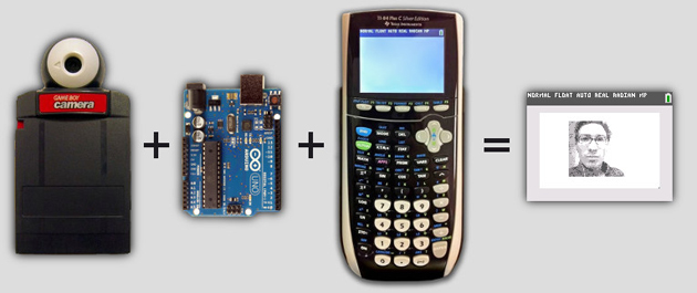
Your graphing calculator may not be getting much use these days now that other mobile devices can do the job, but it still has a few tricks up its sleeve if you're willing to do some tinkering. Christopher Mitchell's latest project, ArTICam, lets you turn a TI-83 Plus or TI-84 Plus calculator into a selfie-oriented camera. The mod mostly requires a Game Boy Camera and a programmable Arduino board like the Uno. After a little bit of wiring and some (thankfully ready-made) code, you can snap self-portraits with a calculator command. The 128 x 123 grayscale pictures you take won't win photography awards, but that's not the point -- this is more about having fun with gadgets that might otherwise sit in the closet gathering dust. Hit the source link if you have the gear and want to give ArTICam a whirl.

[Thanks, Christopher]

Filed under: Cameras, Handhelds, Nintendo

Comments

Source: Cemetech

ArTICam Interfaces Game Boy Camera with TI Calculators

[Christopher Mitchell] has given Texas Instruments calculators the ability to capture images through a Game Boy Camera with ArTICam. First introduced in 1998, The Game Boy Camera was one of the first low-cost digital cameras available to consumers. Since then it has found its way into quite a few projects, including this early Atmel AT90 based hack, and this Morse code transceiver.

TI calculators don’t include a Game Boy cartridge slot, so [Christopher] used an Arduino Uno to interface the two. He built upon the Arduino-TI Calculator Linking (ArTICL) Library  to create ArTICam. Getting the Arduino to talk with the Game Boy Camera’s M64282FP image sensor turned out to be easy, as there already are code examples available. The interface between the camera sensor and the Arduino is simple enough. 6 digital lines for an oddball serial interface, one analog sense line, power and ground. [Christopher] used a shield to solder everything up, but says you can easily get away with wiring directly the Arduino Uno’s I/O pins. The system is compatible with the TI-83 Plus and TI-84 Plus family of calculators. Grabbing an image is as simple as calling  GetCalc(Pic1) from your calculator program.

So, If you have an old calculator lying around, give it a try to enjoy some 128×123-pixel grayscale goodness!


Filed under: Arduino Hacks, classic hacks

Follow your cat with FPV camera and Arduino Leonardo

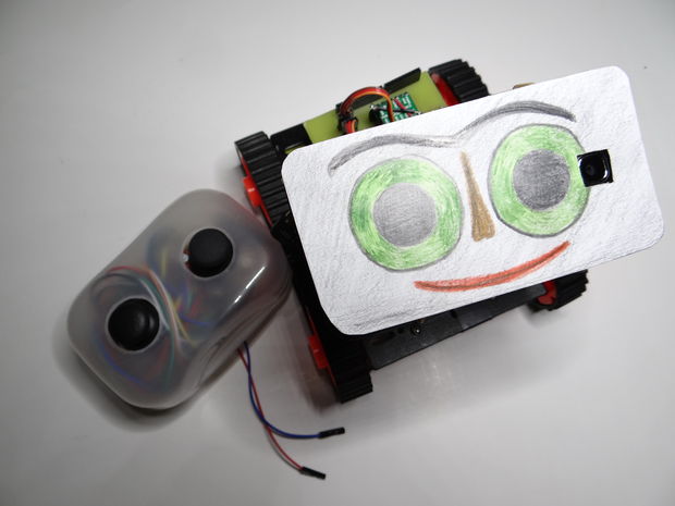
After the Bike Tachometer we posted back in September, Nikus  shared with us a new Instructable to show you how to build remote-controlled tank using a first person view (FPV) camera and Arduino Leonardo:

At the beginning I build only RC tank without FPV camera but when I was driving it in the house I have not seen where it is. So I came up with that I will add to it the camera mounted on a 2 servos. The range is about 100m, you can also ride with it at home. With this tank you can see what your cat is doing when you’re not looking. You can see it on a video

Watch it in action and follow the tutorial:


Arduino Blog 28 Oct 23:07
arduino  camera  featured  fpv  leonardo  robot  

Reverse Engineering a Wireless Studio Lighting Remote

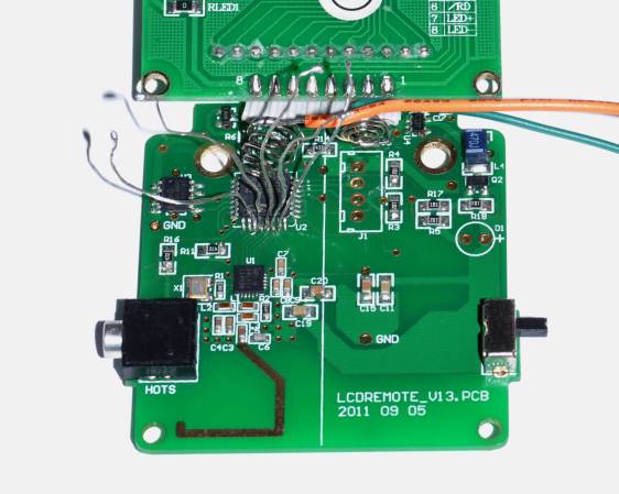
If you want to take a photograph with a professional look, proper lighting is going to be critical. [Richard] has been using a commercial lighting solution in his studio. His Lencarta UltraPro 300 studio strobes provide adequate lighting and also have the ability to have various settings adjusted remotely. A single remote can control different lights setting each to its own parameters. [Richard] likes to automate as much as possible in his studio, so he thought that maybe he would be able to reverse engineer the remote control so he can more easily control his lighting.

[Richard] started by opening up the remote and taking a look at the radio circuitry. He discovered the circuit uses a nRF24L01+ chip. He had previously picked up a couple of these on eBay, so his first thought was to just promiscuously snoop on the communications over the air. Unfortunately the chips can only listen in on up to six addresses at a time, and with a 40-bit address, this approach may have taken a while.

Not one to give up easily, [Richard] chose a new method of attack. First, he knew that the radio chip communicates to a master microcontroller via SPI. Second, he knew that the radio chip had no built-in memory. Therefore, the microcontroller must save the address in its own memory and then send it to the radio chip via the SPI bus. [Richard] figured if he could snoop on the SPI bus, he could find the address of the remote. With that information, he would be able to build another radio circuit to listen in over the air.

Using an Open Logic Sniffer, [Richard] was able to capture some of the SPI communications. Then, using the datasheet as a reference, he was able to isolate the communications that stored information int the radio chip’s address register. This same technique was used to decipher the radio channel. There was a bit more trial and error involved, as [Richard] later discovered that there were a few other important registers. He also discovered that the remote changed the address when actually transmitting data, so he had to update his receiver code to reflect this.

The receiver was built using another nRF24L01+ chip and an Arduino. Once the address and other registers were configured properly, [Richard's] custom radio was able to pick up the radio commands being sent from the lighting remote. All [Richard] had to do at this point was press each button and record the communications data which resulted. The Arduino code for the receiver is available on the project page.

[Richard] took it an extra step and wrote his own library to talk to the flashes. He has made his library available on github for anyone who is interested.


Filed under: Arduino Hacks, radio hacks

Arduino Selfie


My attention is drawn towards the noise behind me....
I cannot believe it.
There it is.

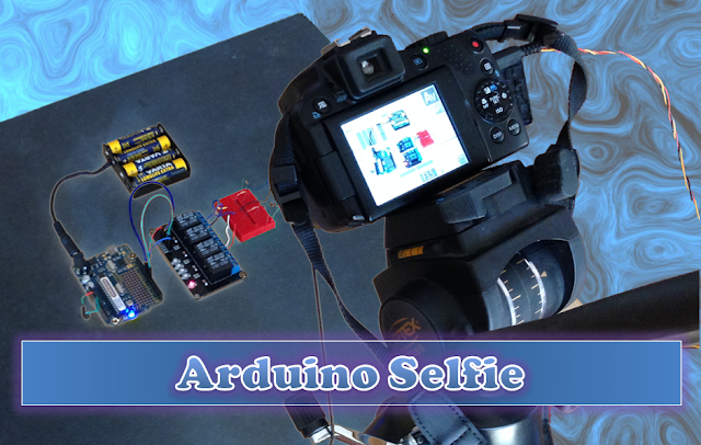
  The Arduino is taking a SELFIE !!


How did this happen?
 
Well actually, it is not that difficult for an Arduino.
 
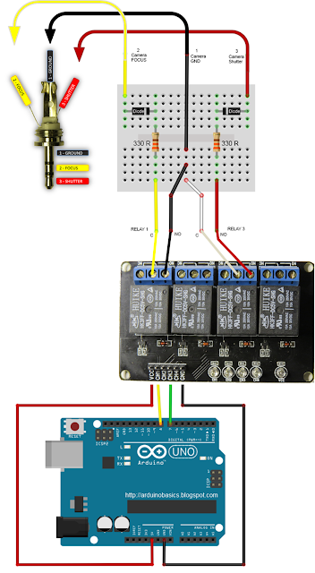
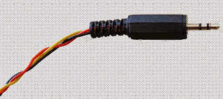
I found out that my Canon Powershot SX50 HS camera has a port on the side for a remote switch. In the "Optional Accessories" section of the camera brochure, it identifies the remote switch model as RS-60E3. I then looked up the model number on this website to find out the size of the jack (3 core, 2.5mm), and the pinout (Ground, focus and shutter) required to emulate the remote switch. Once I had this information, I was able to solder some really long wires to the jack and connect up the circuit (as described below).
 

And before I knew it, the Arduino was taking Selfies !!!


Warning : Any circuit you build for your camera (including this one) is at your own risk. I will not take responsibility for any damage caused to any of your equipment.
 

Parts Required:


Fritzing Sketch


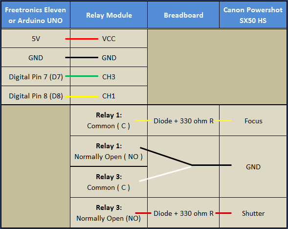
Connection Table


Three core, 2.5 mm jack


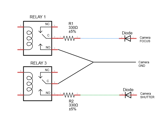
Camera Connection to Relays


Jack pinout


Completed Circuit


Arduino Sketch


  1
2
3
4
5
6
7
8
9
10
11
12
13
14
15
16
17
18
19
20
21
22
23
24
25
26
27
28
29
30
31
32
33
34
35
36
37
38

/* ===============================================================
      Project: Arduino Selfie
       Author: Scott C
      Created: 14th Sept 2014
  Arduino IDE: 1.0.5
      Website: http://arduinobasics.blogspot.com/p/arduino-basics-projects-page.html
  Description: Arduino takes selfie every 30 seconds
================================================================== */

 /*
  Connect 5V on Arduino to VCC on Relay Module
  Connect GND on Arduino to GND on Relay Module */
 
 #define CH1 8   // Connect Digital Pin 8 on Arduino to CH1 on Relay Module
 #define CH3 7   // Connect Digital Pin 7 on Arduino to CH3 on Relay Module
 
 void setup(){
   //Setup all the Arduino Pins
   pinMode(CH1, OUTPUT);
   pinMode(CH3, OUTPUT);
   
   //Turn OFF any power to the Relay channels
   digitalWrite(CH1,LOW);
   digitalWrite(CH3,LOW);
   delay(2000); //Wait 2 seconds before starting sequence
 }
 
 void loop(){
   digitalWrite(CH1, HIGH); //Focus camera by switching Relay 1
   delay(2000);
   digitalWrite(CH1, LOW); //Stop focus
   delay(100);
   digitalWrite(CH3, HIGH); //Press shutter button for 0.5 seconds
   delay(500);
   digitalWrite(CH3,LOW); //Release shutter button
   delay(30000); //Wait 30 seconds before next selfie
 }


By connecting up the camera to an Arduino, the camera just got smarter !!
The Arduino connects to 2 different channels on the relay board in order to control the focus and the shutter of the camera. The relays are used to isolate the camera circuit from that of the Arduino. I have also included a couple of diodes and resistors in the circuit as an extra precaution, however they may not be needed.

Warning : Any circuit you build for your camera (including this one) is at your own risk. I will not take responsibility for any damage caused to any of your equipment. Do your research, and take any precautions you see fit.


The Video


If you like this page, please do me a favour and show your appreciation :

  Visit my ArduinoBasics Google + page.
Follow me on Twitter by looking for ScottC @ArduinoBasics.
Have a look at my videos on my YouTube channel.


However, if you do not have a google profile...
Feel free to share this page with your friends in any way you see fit.

RC Sega Rally @ Codebits VI


Codebits is the most geekest event in Portugal and surroundings!

read more

Let's Make Robots 25 Nov 09:24
arcade  arduino  camera  car  control  game  rc  sega rally  xbee  

DIY Doorbell Video Security System

Ever wonder who comes to your door during the day while you’re gone?  Here’s a simple DIY project to answer that question.  Every time someone rings your doorbell, you’ll receive a text message containing a photo of the person.  The system can also be setup to automatically take photos based upon motion detection instead of a doorbell press.

When someone rings the doorbell, the Arduino instructs a camera to take a picture. It then also sends an email to your smart phone notifying you that someone is at the door.  If you’re nterested in building your own, check out the detailed instructions.

Similar DIY Security Projects:

Hack n Mod 05 Sep 07:29

Joystick operated security cam will overlook the moat

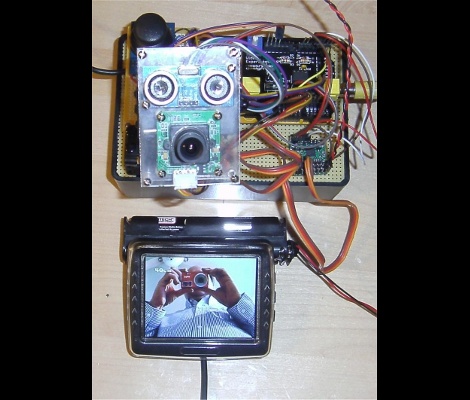
What good is a moat if nobody is guarding it? We suppose that depends on what beasties lurk beneath the surface of the water, but that’s neither here nor there. The members of LVL1 continue their quest to outdo each other in augmenting the building’s automated features. The latest offering is this security camera which is operated with an analog thumb stick.

These are the people who are building a moat (which the city things is a reflecting pool) in front of their main entrance. Now they will be able to see and sense if anyone is trying to get across the watery hazard. The hack marries an ultrasonic rangefinder and camera module with a pair of servo motors. The brackets for the motors allow a full range of motion, and the signal is translated by an Arduino and Video Experimenter shield to put out a composite video signal. That’s not going to make streaming all that easy, but we’re sure that is just one more hack away.


Filed under: Hackerspaces, video hacks

Space experiments for everyone: the ArduSat project

ArduSat, which stands for “Arduino satellite”, is a recently kickstarted project that aims at developing an open platform usable to emulate space scientists:

Once launched, the ArduSat will be the first open platform allowing the general public to design and run their own space-based applications, games and experiments, steer the onboard cameras to take pictures on-demand, and even broadcast personalized messages back to Earth.

ArduSat will be equipped with several sensors (such as cameras, gyros, accelerometers, GPS and more) packed inside a small cube (the side will be approximately 10 cm long) that can be accessed through a set of Arduinos.

Once in orbit, the ArduSat will be accessible from the ground to flash the required firmware for the experiments and for getting back all the collected information. People interested in performing space experiments will have access to a ground replica of ArduSat explotable to test and debug their code before the actual deployment.

The project is very ambitious, and it is expected that such an open accessible space platform will have a considerable impact on how simple space experiments will be carried out in the forthcoming years, in the case of fundraising success.

You may find the Kickstarter page of the project here.

[Via: Hack A Day and Kickstarter]

Salvius

Primary image

What does it do?

Salvius is my humanoid robotics project that I have been working on over the past year. The robot still requires work before it can move around on its own because I still need to get another motor controller. While I search for another Curtis 12v model: 1204 motor controller I continue to work on many other parts of the robot's design. The robot now has night vision and ultrasonic hearing. You can connect to the robot's computer using any wireless enabled device and control the robots actions.

Cost to build

$650,00

Embedded video

Finished project

Number

Time to build

Type

wheels

URL to more information

Weight

120000 grams

read more