Arduino is well known for the large variety of sensors / modules that can be connected. It is quite easy to hook up a temperature or humidity sensor to get instant feedback about the surrounding environmental conditions. However, sometimes you do not have a temperature sensor. Sometimes you have a sensor, but would like to know the temperature in other cities ! Or you would like to know what the temperature will be tomorrow?
Well now you can !!
All you need is a Temboo account, an internet connection and the following components:
Parts Required
Project Description
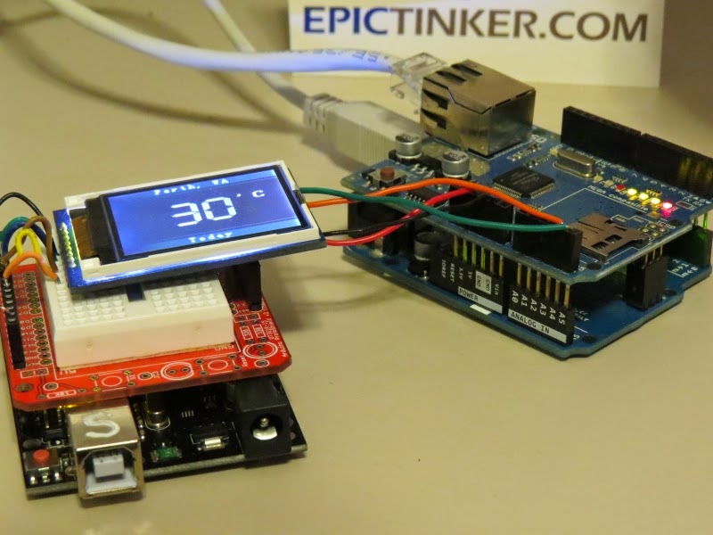
An Arduino UNO (and Ethernet Shield) queries Yahoo using a Temboo account, and retrieves weather information. The data is filtered and processed, and then passed on to another Arduino UNO to be displayed on a TFT LCD module. Two Arduino UNOs are used because the Ethernet library and the UTFT library are both memory hungry, and together consume more memory than one Arduino UNO can handle. Yes - I could have used a different board such as the Arduino MEGA, but where is the fun in that ?? This project will teach you many things:
- How to use an Ethernet Shield with a Temboo account to retrieve internet data
- How to use a TFT LCD module (ITDB02-1.8SP)
- How to reduce memory consumption when using the UTFT library
- How to power two Arduinos with a single USB cable
- How to transmit data from one Arduino to another (via jumper wires)
All of this and a whole lot more !!
Video
Have a look at the following video to see the project in action.

You will need to create a Temboo account to run this project:
Temboo Account Creation
Step 1:
Visit the Temboo website :
https://www.temboo.com/ Create an account by entering a valid email address. Then click on the Sign Up button.
Step 2:
Verify your email address by clicking on the link provided in the email sent by Temboo.
Step 3:
You will be directed to the account setup page: Create an Account Name, and Password for future access to your Temboo Account Check the terms of service and if you agree, then tick the box Press the Go! button
Step 4:
You will then encounter the "Welcome!" screen:
Step 5:
Navigate to the top right of the screen and select the
LIBRARY tab
Step 6:
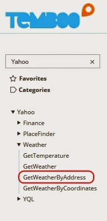
On the left hand side you will see a list of choreos. Type Yahoo into the search box on the top left of the screen. Navigate to the
GetWeatherByAddress Choreo by clicking on... Yahoo _ Weather _ GetWeatherByAddress
Step 7:
Turn the IoT Mode to ON (in the top right of screen)
Step 8:
What's your platform / device? : Arduino
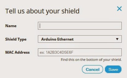
How is it connected? : Arduino Ethernet The following popup box will appear:
Step 9:
Name: EthernetShield - you can choose any name. Letters and numbers only. No spaces.
Shield Type: Arduino Ethernet
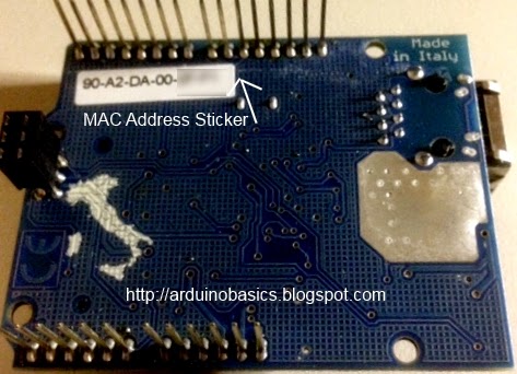
MAC Address : You can normally find the MAC address of the Ethernet shield on the underside. Enter the MAC address without the hyphens. Then click SAVE.
Step 10:
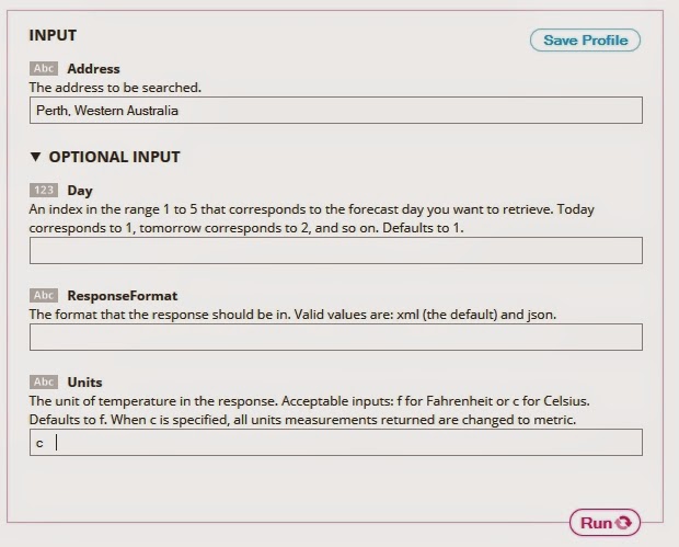
Move to the INPUT section. Enter the Address of the place you want the Temperature for.
Address = Perth, Western Australia Expand the Optional INPUT for extra functionality
Units = c - If you want the temperature in Celcius.
Step 11:
This will automatically generate some Arduino CODE and a HEADER FILE. Don't worry about the Arduino code for now... because I will provide that for you. However, you will need the automatically generated HEADER file. I will show you what to do with that soon. So don't lose it !'
Temboo Library Install
The Temboo library will need to be installed before you copy the Arduino code in the sections below. To install the Temboo library into your Arduino IDE, please follow the link to their instructions:
Installing the Temboo Arduino Library
UTFT Library Install
Download the UTFT library from this site:
http://www.henningkarlsen.com/electronics/library.php?id=51 Once downloaded and extracted. Go into the UTFT folder and look for the
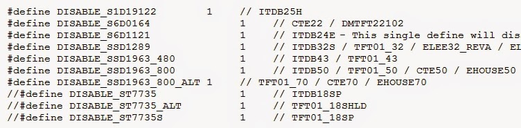
memorysaver.h file. Open this file in a text editor, and "uncomment" all of the TFT modules that are not relevant to this project. I disabled all of the TFT modules except the last 3 (which made reference to ST7735) - see picture below. The TFT module we are using in this project is the ITDB02-1.8SP from ITEAD Studio. Save the memorysaver.h file, and then IMPORT the library into the Arduino IDE as per the normal library import procedure.
If you do not modify the memorysaver.h file, the Arduino SLAVE sketch will not compile.
Arduino Code (MASTER)
This project uses 2 Arduino UNOs. One will be the Master, and one will be the Slave. The following code is for the Arduino MASTER. Open up the Arduino IDE. (I am using Arduino IDE version 1.6) Paste the following code into the Arduino IDE code window.
PLEASE NOTE: You may need to change some of the lines to accomodate your INPUTS from step 10. Have a look around line 36 and 37.
1
2
3
4
5
6
7
8
9
10
11
12
13
14
15
16
17
18
19
20
21
22
23
24
25
26
27
28
29
30
31
32
33
34
35
36
37
38
39
40
41
42
43
44
45
46
47
48
49
50
51
52
53
54
55
56
57
58
59
60
61
62
63
64
65
66
67
68
69
70
71
72
73
74
75
76
77
78
79
80
81
82
83
84
85
86
87
88
89
90
91
92
93
94
95
96
97
98
99
100
101
102
103
104
105
106
107
108
109
110
111
112
113
114
115
116
117
118
119
120
121
122
123
124
125
126
127
128
129
130
131
132
132
133
134
135
136
137
138
139
140
141
142
143
144
145
146
147
148
149
150
151
152
153
154
155
156
157
158
159
160
161
162
163
164
165
166
167
168
169
170
171
172
173
174
175
176
177
178
179
180
181
182
183
184
185
186
187
|
/* ===============================================================================
Project: Weather Reporter: Temboo, Ethernet, Arduino
Title: ARDUINO MASTER: Get temperature from Yahoo using Temboo
Author: Scott C
Created: 27th February 2015
Arduino IDE: 1.6.0
Website: http://arduinobasics.blogspot.com/p/arduino-basics-projects-page.html
Description: The following sketch was designed for the Arduino MASTER device.
It will retrieve temperature/weather information from Yahoo using your
Temboo account (https://www.temboo.com/), which will then be sent to the
Arduino Slave device to be displayed on a TFT LCD module.
Libraries : Ethernet Library (that comes with Arduino IDE)
Temboo Arduino Library - https://www.temboo.com/sdk/arduino
Temboo Library installation instructions for Arduino:
https://www.temboo.com/arduino/others/library-installation
You will also need to copy your Temboo Account information into a new tab and call it TembooAccount.h.
Please follow the instructions on the ArduinoBasics blog for more information.
---------------------------------------------------------------------------------- */
#include <SPI.h>
#include <Dhcp.h>
#include <Dns.h>
#include <Ethernet.h>
#include <EthernetClient.h>
#include <Temboo.h>
#include "TembooAccount.h" // Contains Temboo account information - in a new tab.
#include <Wire.h>
byte ethernetMACAddress[] = ETHERNET_SHIELD_MAC; //ETHERNET_SHIELD_MAC variable located in TembooAccount.h
EthernetClient client;
String Address = "Perth, Western Australia"; // Find temperature for Perth, Western Australia
String Units = "c"; // Display the temperature in degrees Celcius
String ForeCastDay[7]; //String Array to hold the day of the week
String ForeCastTemp[7]; //String Array to hold the temperature for that day of week.
int counter1=0; //Counters used in FOR-LOOPS.
int counter2=0;
boolean downloadTemp = true; // A boolean variable which controls when to query Yahoo for Temperature information.
void setup() {
Wire.begin(); // join i2c bus : Used to communicate to the Arduino SLAVE device.
// Ethernet shield must initialise properly to continue with sketch.
if (Ethernet.begin(ethernetMACAddress) == 0) {
while(true);
}
//Provide some time to get both Arduino's ready for Temperature Query.
delay(2000);
}
void loop() {
if (downloadTemp) {
downloadTemp=false; //Stop Arduino from Querying Temboo repeatedly
getTemperature(); //Retrieve Temperature data from Yahoo
transmitResults(); //Transmit the temperature results to the Slave Arduino
}
}
/* This function will Query Yahoo for Temperature information (using a Temboo account) */
void getTemperature(){
TembooChoreo GetWeatherByAddressChoreo(client);
// Invoke the Temboo client
GetWeatherByAddressChoreo.begin();
// Set Temboo account credentials
GetWeatherByAddressChoreo.setAccountName(TEMBOO_ACCOUNT); //TEMBOO_ACCOUNT variable can be found in TembooAccount.h file or tab
GetWeatherByAddressChoreo.setAppKeyName(TEMBOO_APP_KEY_NAME); //TEMBOO_APP_KEY_NAME variable can be found in TembooAccount.h file or tab
GetWeatherByAddressChoreo.setAppKey(TEMBOO_APP_KEY); //TEMBOO_APP_KEY variable can be found in TembooAccount.h file or tab
// Set Choreo inputs
GetWeatherByAddressChoreo.addInput("Units", Units); // Set the Units to Celcius
GetWeatherByAddressChoreo.addInput("Address", Address); // Set the Weather Location to Perth, Western Australia
// Identify the Choreo to run
GetWeatherByAddressChoreo.setChoreo("/Library/Yahoo/Weather/GetWeatherByAddress");
// This output filter will extract the expected temperature for today
GetWeatherByAddressChoreo.addOutputFilter("Temperature", "/rss/channel/item/yweather:condition/@temp", "Response");
// These output filters will extract the forecasted temperatures (we need to know the day and temperature for that day)
GetWeatherByAddressChoreo.addOutputFilter("ForeCastDay", "/rss/channel/item/yweather:forecast/@day", "Response");
GetWeatherByAddressChoreo.addOutputFilter("ForeCastHigh", "/rss/channel/item/yweather:forecast/@high", "Response");
// Run the Choreo;
GetWeatherByAddressChoreo.run();
//Reset our counters before proceeding
counter1 = 0;
counter2 = 0;
while(GetWeatherByAddressChoreo.available()) {
// This will get the first part of the output
String name = GetWeatherByAddressChoreo.readStringUntil('\x1F');
name.trim(); // get rid of newlines
// This will get the second part of the output
String data = GetWeatherByAddressChoreo.readStringUntil('\x1E');
data.trim(); // get rid of newlines
//Fill the String Arrays with the Temperature/Weather data
if (name == "Temperature") {
ForeCastDay[counter1] = "Today";
ForeCastTemp[counter2] = data;
counter1++;
counter2++;
}
if(name=="ForeCastDay"){
ForeCastDay[counter1] = data;
counter1++;
}
if(name=="ForeCastHigh"){
ForeCastTemp[counter2] = data;
counter2++;
}
}
//Close the connection to Temboo website
GetWeatherByAddressChoreo.close();
}
/* This function is used to transmit the temperature data to the Slave Arduino */
void transmitResults(){
char tempData[10];
int tempStringLength = 0;
//Modify the current temp to "Now"
ForeCastDay[0] = "Now";
//Send * to Slave Arduino to prepare for Temperature Transmission
Wire.beginTransmission(4); // Transmit to device #4 (Slave Arduino)
Wire.write("*");
delay(500);
Wire.endTransmission();
delay(500);
//Send the temperatures on the Slave Arduino to be displayed on the TFT module.
for (int j=0; j<20; j++){
for (int i=0; i<6; i++){
memset(tempData,0,sizeof(tempData)); //Clear the character array
String tempString = String(ForeCastDay[i] + "," + ForeCastTemp[i] + ".");
tempStringLength = tempString.length();
tempString.toCharArray(tempData, tempStringLength+1);
Wire.beginTransmission(4); // Transmit to device #4 (Slave Arduino)
Wire.write(tempData);
delay(1000);
Wire.endTransmission();
delay(4000);
}
}
/* ----------------------------------------------------------------------
// You can use this to send temperature results to the Serial Monitor.
// However, you will need a Serial.begin(9600); statement in setup().
Serial.println("The Current Temperature is " + ForeCastTemp[5] + " C");
Serial.println();
Serial.println("The Expected Temperature for");
for (int i=0; i<5; i++){
Serial.println(ForeCastDay[i] + " : " + ForeCastTemp[i] + " C");
}
---------------------------------------------------------- */
}
|
Select "New Tab" from the drop-down menu on the top right of the IDE.
Name the file: TembooAccount.h
Paste the contents of the HEADER file from the Temboo webpage (Step 11 above) into the TembooAccount.h tab. If you do not have the TembooAccount.h tab with the contents of this HEADER file next to your Arduino Master sketch, then it will NOT work.
Make sure to SAVE the Arduino Sketch and upload the code to the Arduino (MASTER)
Arduino Code (SLAVE)
This project uses 2 Arduino UNOs. One will be the Master, and one will be the Slave. The following code is for the Arduino SLAVE. Make sure to disconnect the Arduino MASTER from your computer, and keep it to one side. Connect the Arduino SLAVE to your computer, and upload the following code to it. Make sure to create a new sketch for this code (File _ New).
  1
  2
  3
  4
  5
  6
  7
  8
  9
 10
 11
 12
 13
 14
 15
 16
 17
 18
 19
 20
 21
 22
 23
 24
 25
 26
 27
 28
 29
 30
 31
 32
 33
 34
 35
 36
 37
 38
 39
 40
 41
 42
 43
 44
 45
 46
 47
 48
 49
 50
 51
 52
 53
 54
 55
 56
 57
 58
 59
 60
 61
 62
 63
 64
 65
 66
 67
 68
 69
 70
 71
 72
 73
 74
 75
 76
 77
 78
 79
 80
 81
 82
 83
 84
 85
 86
 87
 88
 89
 90
 91
 92
 93
 94
 95
 96
 97
 98
 99
100
101
102
103
104
105
106
107
108
109
110
111
112
113
114
115
116
117
118
119
120
121
122
123
124
125
126
127
128
129
130
131
132
133
134
135
136
137
138
139
140
141
142
143
144
145
146
147
148
149
150
151
152
153
154
155
156
157
158
159
160
161
162
163
164
165
166
167
168
169
170
171
172
173
174
175
176
177
178
179
180
181
182
183
184
185
186
187
188
189
190
191
192
193
194
195
196
197
|
/* ===============================================================================
Project: Weather Reporter: Temboo, Ethernet, Arduino
Title: ARDUINO SLAVE: Display temperature on TFT LCD Module
Author: Scott C
Created: 27th February 2015
Arduino IDE: 1.6.0
Website: http://arduinobasics.blogspot.com/p/arduino-basics-projects-page.html
Description: The following sketch was designed for the Arduino SLAVE device.
It will receive temperature information from the Arduino MASTER
and then display this information on the ITDB02-1.8SP TFT LCD
Module. Please read the important notes below.
----------------------------------------------------------------------------------
NOTES:
This sketch makes use of the UTFT.h library from :
http://www.henningkarlsen.com/electronics/library.php?id=51
Please note: You will need to modify the memorysaver.h file in the UTFT folder
with a text editor to disable any unused TFT modules. This will save memory,
and allow you to run this sketch on an Arduino UNO. I disabled all TFT modules in
that file except the last 3 (which made reference to ST7735).
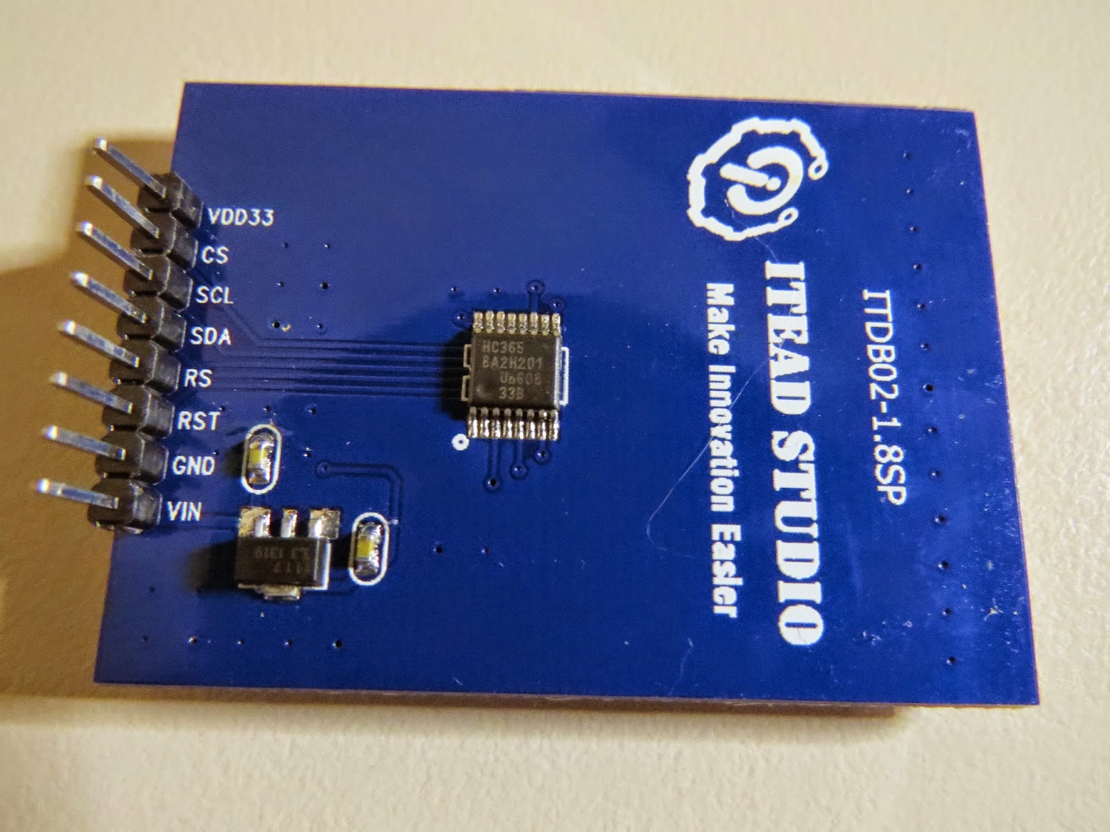
I used a ITDB02-1.8SP TFT LCD Module from ITEAD Studio.
PinOut:
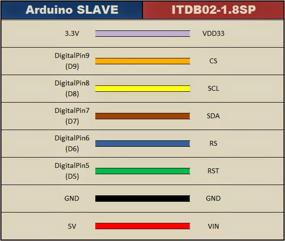
Arduino SLAVE ITDB02-1.8SP TFT
3.3V ---- VDD33
Digital9 (D9)---- CS
Digital8 (D8)---- SCL
Digital7 (D7)---- SDA
Digital6 (D6)---- RS
Digital5 (D5)---- RST
GND ---- GND
5V ---- VIN
Usage: UTFT myGLCD(<model code>, SDA, SCL, CS, RST, RS);
Example: UTFT myGLCD(ITDB18SP,7,8,9,5,6);
-----------------------------------------------------------------------------------
This sketch also makes use of the Wire.h library.
The Wire.h library comes with the Arduino IDE.
This enables communication between Arduino Master and Arduino Slave.
PinOut:
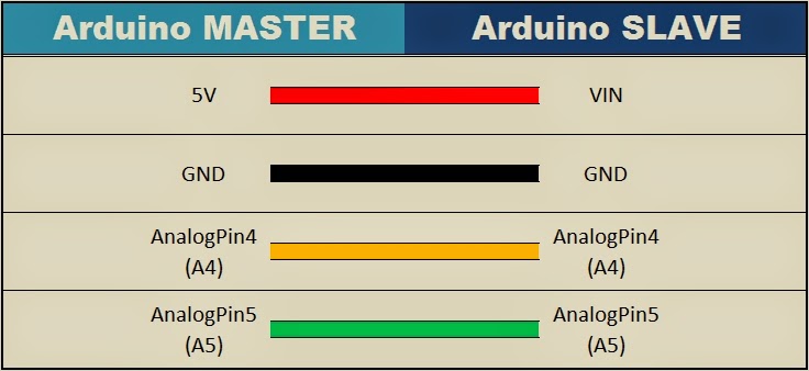
Arduino MASTER Arduino SLAVE
Analog4(A4) ---- Analog4 (A4)
Analog5(A5) ---- Analog5 (A5)
GND ---- GND
-----------------------------------------------------------------------------------
The Arduino Slave is powered by the Arduino Master:
PinOut:
Arduino MASTER Arduino SLAVE
5V ---- VIN
==================================================================================
*/
#include <UTFT.h>
#include <Wire.h>
//Declare all of the fonts
extern uint8_t SmallFont[];
extern uint8_t BigFont[];
extern uint8_t SevenSegNumFont[];
// Usage: UTFT myGLCD(<model code>, SDA, SCL, CS, RST, RS);
UTFT myGLCD(ITDB18SP,7,8,9,5,6);
boolean tempDisplay = false; //Helps with processing the data from the Arduino MASTER
boolean readTemp = false; //Helps to differentiate the day from the temperature values
String dayOfWeek=""; //Variable used to hold the Day of the Week
String tempReading=""; //Variable used to hold the Temperature for that day
String Units = "'C "; //Display Temperature in Celcius
String Address = "Perth, WA"; //Address to show at top of Display
void setup(){
// Initialise the TFT LCD
myGLCD.InitLCD();
initialiseLCD();
delay(5000);
//Setup the Serial communication between the Arduino MASTER and SLAVE
Wire.begin(4); // join i2c bus with address #4
Wire.onReceive(receiveEvent); // register event
}
void loop(){
delay(50);
}
/*
This function initialises the TFT LCD, and draws the initial screen.
*/
void initialiseLCD(){
//Clear the screen
myGLCD.clrScr();
//Draw the borders (top and bottom)
myGLCD.setColor(25, 35, 4);
myGLCD.fillRect(0, 0, 159, 13);
myGLCD.fillRect(0, 114, 159, 127);
myGLCD.drawLine(0,18,159,18);
myGLCD.drawLine(0,109,159,109);
//Header and Footer Writing
myGLCD.setColor(255, 255, 255);
myGLCD.setBackColor(25, 35, 4);
myGLCD.setFont(SmallFont);
myGLCD.print("arduinobasics", CENTER, 1);
myGLCD.print("blogspot.com", CENTER, 114);
}
/* This function executes whenever data is received from Arduino master
It will ignore all data from the Master until it receives a '*' character.
Once this character is received, it will call the receiveTemp() function
in order to receive Temperature data from the Arduino Master.
*/
void receiveEvent(int howMany){
if(tempDisplay){
receiveTemp();
}else{
while(0 < Wire.available()){
char c = Wire.read(); // receive byte as a character
if(c=='*'){ // Searching for a '*' character
tempDisplay=true; // If '*' received, then call receiveTemp() function
}
}
}
}
/* This function is used to receive and process the Temperature data
from the Arduino Master and pass it on to the displayTemp() funtion.
*/
void receiveTemp(){
tempReading="";
dayOfWeek = "";
while(0 < Wire.available()){
char c = Wire.read(); // receive byte as a character
if(readTemp){
if(c=='.'){ // If a . is detected. It is the end of the line.
readTemp=false;
}else{
tempReading=tempReading+c;
}
}else{
if(c==','){
} else {
dayOfWeek=dayOfWeek+c;
}
}
if(c==','){
readTemp=true;
}
}
displayTemp();
}
/*
Display the Temperature readings on the TFT LCD screen.
*/
void displayTemp(){
//Clear the writing on top and bottom of screen
myGLCD.setColor(25, 35, 4);
myGLCD.fillRect(0, 0, 159, 13);
myGLCD.fillRect(0, 114, 159, 127);
//Small writing on top and bottom of screen
myGLCD.setColor(255, 255, 255);
myGLCD.setBackColor(25, 35, 4);
myGLCD.setFont(SmallFont);
myGLCD.print(Address, CENTER, 1);
myGLCD.print(dayOfWeek, CENTER, 114);
//Write the big temperature reading in middle of screen
myGLCD.setBackColor(0, 0, 0);
myGLCD.setFont(SevenSegNumFont);
myGLCD.print(tempReading, CENTER, 40);
//Write the Units next to the temperature reading
myGLCD.setFont(BigFont);
myGLCD.print(Units, RIGHT, 40);
}
|
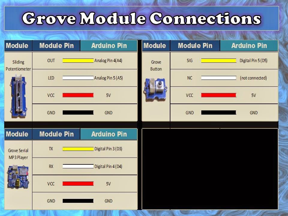
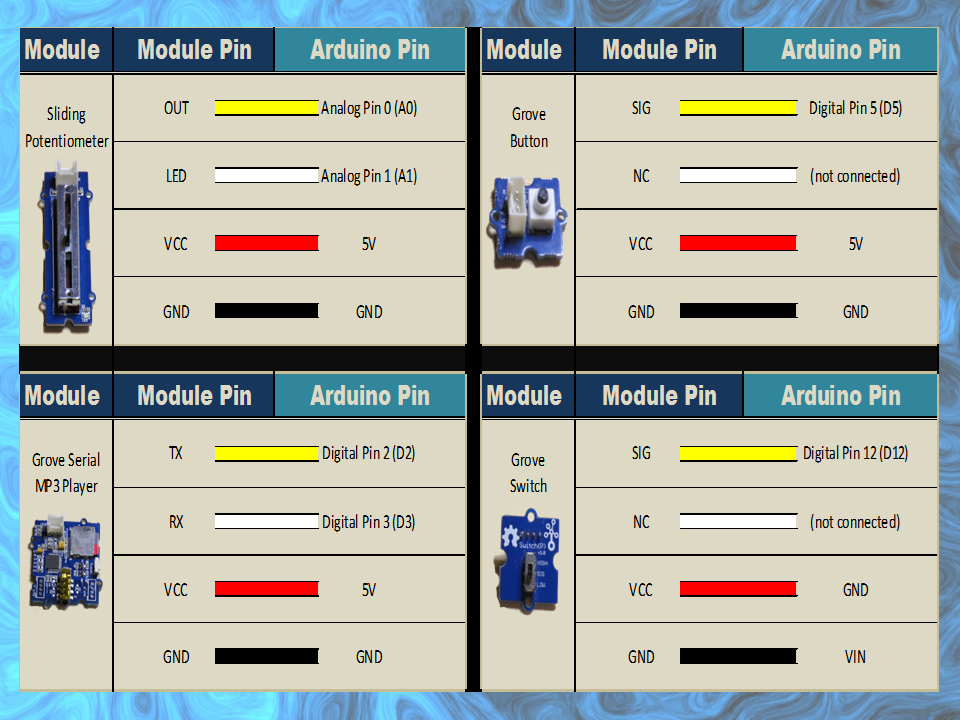
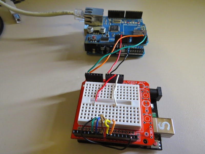
Wiring it up
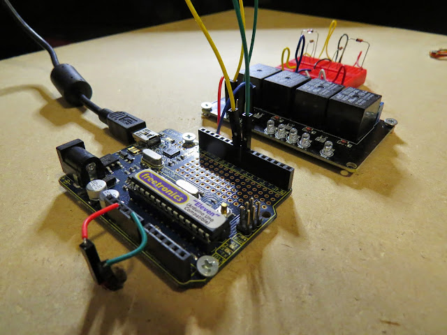
Once the code has been uploaded to both Arduinos (Master and Slave), I tend to label each Arduino so that I don't mix them up. You will notice an 'S' marked on the SLAVE in some of the photos/videos. Then it is time to piggy-back the shields onto the Arduinos and wire them up. Make sure you disconnect the USB cable from the Arduinos before you start doing this.
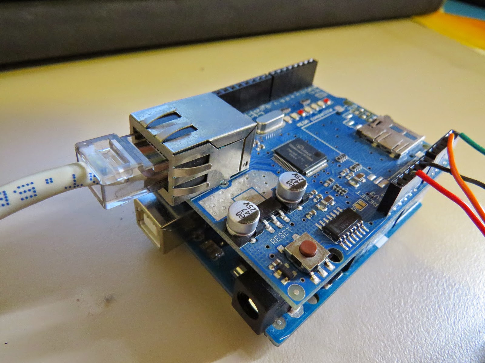
Step 1: Ethernet Shield
Place the Ethernet shield onto the Arduino MASTER. Connect an Ethernet cable (RJ45) to the Ethernet shield. The other end will connect to your internet router.
Step 2: Arduino SLAVE and TFT LCD module
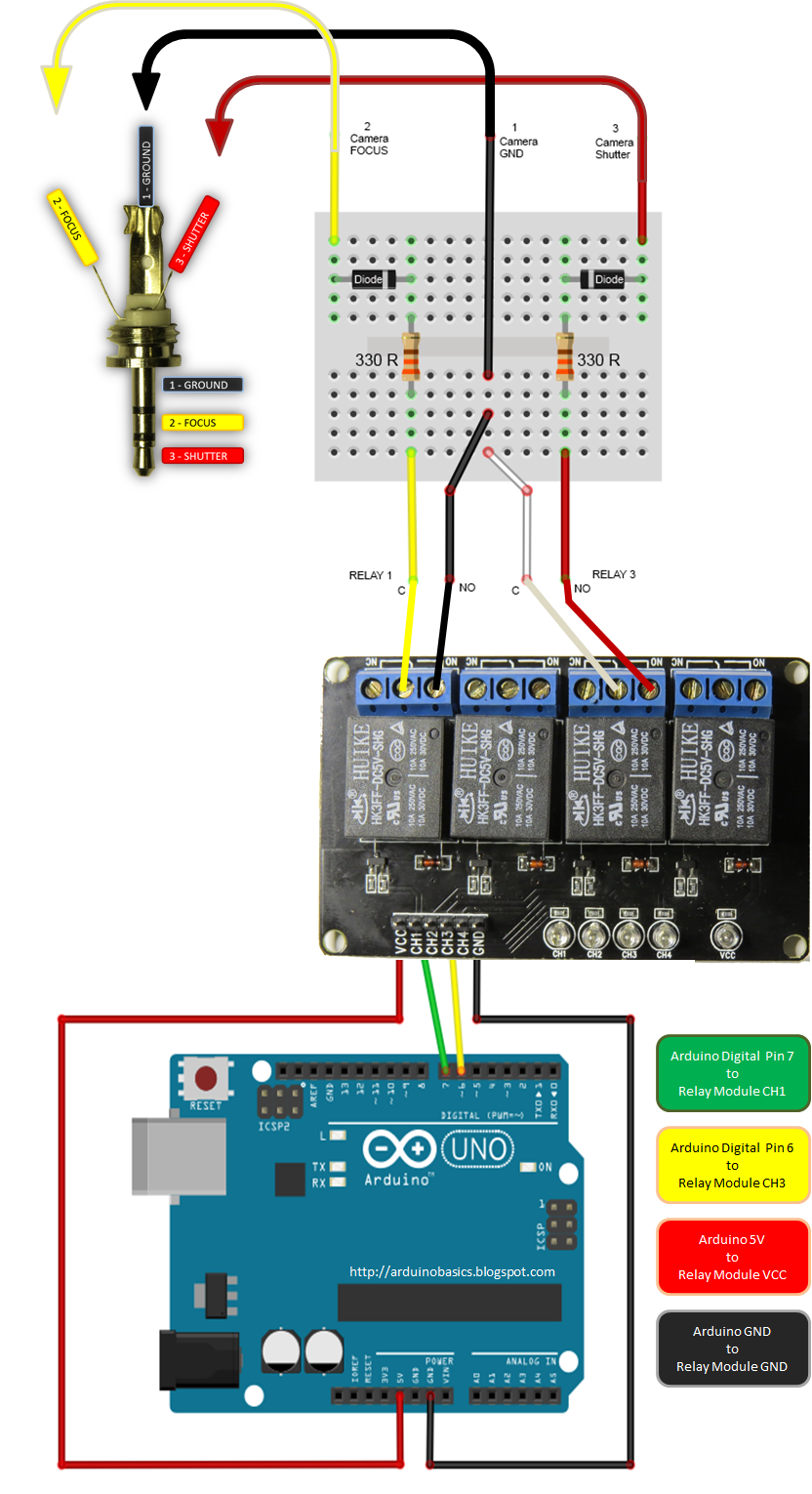
You can either wire up the TFT LCD module on a breadboard, or you can use a ProtoShield with mini-breadboard. It doesn't really matter how you hook it up, but make sure you double check the connections and the TFT specifications before you power it up. I have powered the Arduino Slave by connecting it to the Arduino Master (see fritzing sketch below).
There is no reason why you couldn't just power the slave seperately. In fact this is probably the safer option. But I read that this power-sharing setup was ok, so I wanted to give it a go. I have no idea whether it would be suitable for a long term power project... so use it at your own risk. I tried using 4 x AA batteries to power this circuit, but found that the LCD screen would flicker. So then I tried a 9V battery, and noticed that the 5V voltage regulator was heating up more than I felt comfortable with. In the end, I settled with the USB option, and had no further issues. I am sure there are other possible options, and feel free to mention them in the comments below.
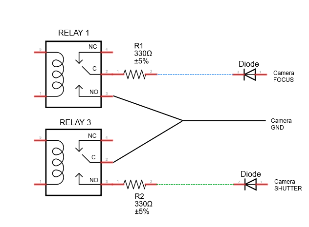
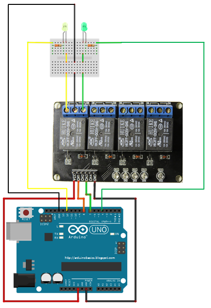
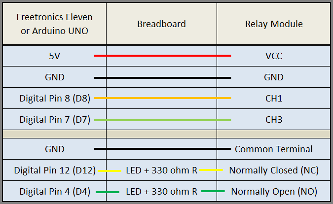
Use the following fritzing sketch and tables to help you wire this circuit up.
Fritzing sketch
Arduino MASTER to SLAVE connection table
Arduino SLAVE to ITDB02-1.8SP TFT LCD
ITDB02-1.8SP TFT LCD Module Pictures
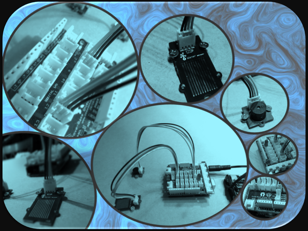
Project Pictures
However, if you do not have a google profile...
Feel free to share this page with your friends in any way you see fit.