Posts with «arduinobasics» label

433 MHz RF module with Arduino Tutorial 3


Project 3: RF Remote Control Emulation

In the first tutorial, I introduced the 433 MHz Transmitter and Receiver with a simple sketch to test their functionality. In the second tutorial, the 433MHz receiver was used to receive a signal from an RF remote. The RF remote signal was coded based on the pattern and length of its HIGH and LOW signals. The signals received by the remote can be described by the code below:

 
Code comparison table


The RF remote that I am using transmits the same signal 6 times in a row. The signal to turn the light on is different from that used to turn the light off. In tutorial 2, we were able to "listen to" or receive the signal from the RF remote using the RF receiver. I thought it would be possible to just play back the signal received on the Arduino's analogPin, but the time it takes to perform a digital write is different to the time it takes to do an AnalogRead. Therefore it won't work. You need to slow down the digitalWrite speed.
I would like to find out if it is possible to apply this delay to all 433 MHz signal projects, however, I only have one 433 MHz remote.

If the delay in your project is the same as mine (or different) I would be keen to know - please leave a comment at the end of the tutorial.

We are going to use trial and error to find the optimal digitalWrite delay time. We will do this by slowly incrementing the delay until the transmission is successful. The transmission is considered successful if the fan-light turns on/off. All we have to do is count the number of transmissions until it is successful, then we should be able to calculate the delay.


Parts Required


The Transmitter Fritzing Sketch


RF Calibration - Arduino Sketch

 1
2
3
4
5
6
7
8
9
10
11
12
13
14
15
16
17
18
19
20
21
22
23
24
25
26
27
28
29
30
31
32
33
34
35
36
37
38
39
40
41
42
43
44
45
46
47
48
49
50
51
52
53
54
55
56
57
58
59
60
61
62
63
64
65
66
67
68
69
70
71
72
73
74
75
76
77
78
79
80
81
82
83
84
85
86
87
88
89
90
91
92
93
94
95
96
97
98
99
100
101
102
103
104
105
106
107
108
109
110
111
112
113
114
115
116
117
118
119
120
121
122
123
124
125
126
127
128
/* 
  Transmit sketch - RF Calibration
     Written by ScottC 17 July 2014
     Arduino IDE version 1.0.5
     Website: http://arduinobasics.blogspot.com
     Transmitter: FS1000A/XY-FST
     Description: A simple sketch used to calibrate RF transmission.          
 ------------------------------------------------------------- */

 #define rfTransmitPin 4  //RF Transmitter pin = digital pin 4
 #define ledPin 13        //Onboard LED = digital pin 13
 
 const int codeSize = 25; //The size of the code to transmit
 int codeToTransmit[codeSize]; //The array used to hold the RF code
 int lightON[]={2,2,2,2,1,4,4,4,4,5,1,4,4,4,4,4,4,5,2,2,1,4,4,4,6}; //The RF code that will turn the light ON
 int lightOFF[]={2,2,2,2,1,4,4,4,4,5,1,4,4,4,4,4,4,5,2,2,2,2,2,2,3}; //The RF code that will turn the light OFF
 int codeToggler = 0; //Used to switch between turning the light ON and OFF
 int timeDelay=5; // The variable used to calibrate the RF signal lengths.


 void setup(){
   Serial.begin(9600); // Turn the Serial Protocol ON
   pinMode(rfTransmitPin, OUTPUT); //Transmit pin is an output
   pinMode(ledPin, OUTPUT);
  
 //LED initialisation sequence - gives us some time to get ready
  digitalWrite(ledPin, HIGH);
  delay(3000);
  digitalWrite(ledPin, LOW);
  delay(1000);
 }


  void loop(){
    toggleCode();    // switch between light ON and light OFF
    transmitCode();  // transmit the code to RF receiver on the Fan/Light
    
    timeDelay+=10;    //Increment the timeDelay by 10 microseconds with every transmission
    delay(2000); //Each transmission will be about 2 seconds apart.
  }


  /*----------------------------------------------------------------
     toggleCode(): This is used to toggle the code for turning 
                   the light ON and OFF 
  -----------------------------------------------------------------*/
  void toggleCode(){
    if(codeToggler){
       for(int i = 0; i<codeSize; i++){
         codeToTransmit[i]=lightON[i];
       } 
      
    } else{
      for(int i = 0; i<codeSize; i++){
         codeToTransmit[i]=lightOFF[i];
       } 
    }
    codeToggler=!codeToggler;
  }


  /*-----------------------------------------------------------------
    transmitCode(): Used to transmit the signal to the RF receiver on
                    the fan/light. There are 6 different HIGH-LOW signal combinations. 
                    
                    SH = short high   or  LH = long high   
                                     PLUS
         SL = short low    or    LL = long low    or    VLL = very long low
                    
  -------------------------------------------------------------------*/
   void transmitCode(){
    // The LED will be turned on to create a visual signal transmission indicator.
    digitalWrite(ledPin, HIGH);
   
   //initialise the variables
    int highLength = 0;
    int lowLength = 0;
    
    //The signal is transmitted 6 times in succession - this may vary with your remote.
    for(int j = 0; j<6; j++){
      for(int i = 0; i<codeSize; i++){
        switch(codeToTransmit[i]){
          case 1: // SH + SL
            highLength=3;
            lowLength=3;
          break;
          case 2: // SH + LL
            highLength=3;
            lowLength=7;
          break;
          case 3: // SH + VLL
            highLength=3;
            lowLength=92;
          break;
          case 4: // LH + SL
            highLength=7;
            lowLength=3;
          break;
          case 5: // LH + LL
            highLength=7;
            lowLength=7;
          break;
          case 6: // LH + VLL
            highLength=7;
            lowLength=92;
          break;
        }
           
         /* Transmit a HIGH signal - the duration of transmission will be determined
            by the highLength and timeDelay variables */
         digitalWrite(rfTransmitPin, HIGH);
         delayMicroseconds(highLength*timeDelay);
         
         /* Transmit a LOW signal - the duration of transmission will be determined
            by the lowLength and timeDelay variables */
         digitalWrite(rfTransmitPin,LOW);
         delayMicroseconds(lowLength*timeDelay);
      }
    }
    //Turn the LED off after the code has been transmitted.
    digitalWrite(ledPin, LOW);
 }
I used an array to hold the RF code for light ON and light OFF. Each number within the code represents a specific sequence of HIGH and LOW lengths. For example, 2 represents a SHORT HIGH and a LONG LOW combination. A short length = 3, a long length = 7, and a very long length = 92. You need to multiply this by the timeDelay variable to identify how much time to transmit the HIGH and LOW signals for.
The short and long lengths were identified from the experiments performed in tutorial 2 (using the RF receiver). Each code is transmitted 6 times. The LED is turned on at the beginning of each transmission, and then turned off at the end of the transmission. The timeDelay variable starts at 5 microseconds, and is incremented by 10 microseconds with every transmission.
In the video, you will notice that there is some flexibility in the timeDelay value. The Mercator Fan/Light will turn on and off when the timeDelay variable is anywhere between 75 and 135 microseconds in length. It also seems to transmit successfully when the timeDelay variable is 175 microseconds.
So in theory, if we want to transmit a signal to the fan/light, we should be able to use any value between 75 and 135, however in future projects, I think I will use a value of 105, which is right about the middle of the range.


Video


  Now that I have the timeDelay variable, I should be able to simplify the steps required to replicate a remote control RF signal. Maybe there is room for one more tutorial on this topic :)

Update: Here it is - tutorial 4
Where you can record and playback an RF signal (without using your computer).


433 MHz RF module with Arduino Tutorial 3


There are 4 parts to this tutorial:
To get the most out of this tutorial - it is best to start at tutorial Part 1, and then progress to Part 2 then Part 3 and then do Part 4 last. Doing the RF tutorials in this order will help you to understand the process better.


Project 3: RF Remote Control Emulation

In the first tutorial, I introduced the 433 MHz Transmitter and Receiver with a simple sketch to test their functionality. In the second tutorial, the 433MHz receiver was used to receive a signal from an RF remote. The RF remote signal was coded based on the pattern and length of its HIGH and LOW signals. The signals received by the remote can be described by the code below:

 
Code comparison table


The RF remote that I am using transmits the same signal 6 times in a row. The signal to turn the light on is different from that used to turn the light off. In tutorial 2, we were able to "listen to" or receive the signal from the RF remote using the RF receiver. I thought it would be possible to just play back the signal received on the Arduino's analogPin, but the time it takes to perform a digital write is different to the time it takes to do an AnalogRead. Therefore it won't work. You need to slow down the digitalWrite speed.
I would like to find out if it is possible to apply this delay to all 433 MHz signal projects, however, I only have one 433 MHz remote.

If the delay in your project is the same as mine (or different) I would be keen to know - please leave a comment at the end of the tutorial.

We are going to use trial and error to find the optimal digitalWrite delay time. We will do this by slowly incrementing the delay until the transmission is successful. The transmission is considered successful if the fan-light turns on/off. All we have to do is count the number of transmissions until it is successful, then we should be able to calculate the delay.


Parts Required


The Transmitter Fritzing Sketch


RF Calibration - Arduino Sketch


I used an array to hold the RF code for light ON and light OFF. Each number within the code represents a specific sequence of HIGH and LOW lengths. For example, 2 represents a SHORT HIGH and a LONG LOW combination. A short length = 3, a long length = 7, and a very long length = 92. You need to multiply this by the timeDelay variable to identify how much time to transmit the HIGH and LOW signals for.
The short and long lengths were identified from the experiments performed in tutorial 2 (using the RF receiver). Each code is transmitted 6 times. The LED is turned on at the beginning of each transmission, and then turned off at the end of the transmission. The timeDelay variable starts at 5 microseconds, and is incremented by 10 microseconds with every transmission.
In the video, you will notice that there is some flexibility in the timeDelay value. The Mercator Fan/Light will turn on and off when the timeDelay variable is anywhere between 75 and 135 microseconds in length. It also seems to transmit successfully when the timeDelay variable is 175 microseconds.
So in theory, if we want to transmit a signal to the fan/light, we should be able to use any value between 75 and 135, however in future projects, I think I will use a value of 105, which is right about the middle of the range.


Video


  Now that I have the timeDelay variable, I should be able to simplify the steps required to replicate a remote control RF signal. Maybe there is room for one more tutorial on this topic :)

Update: Here it is - tutorial 4
Where you can record and playback an RF signal (without using your computer).


433 MHz RF module with Arduino Tutorial 2

Project 2: RF Remote Copy

In the previous project, we transmitted a signal wirelessly from one Arduino to another. It was there to help troubleshoot communication between the modules. It was important to start with a very short distance (1-2 cm) and then move the RF modules further apart to test the range. The range can be extended by soldering an antenna to the module, or by experimenting with different voltage supplies to the modules (making sure to keep within the voltage limits of the modules.)

In this project - we aim to receive a signal from an RF remote. The remote that I am using is a Mercator Remote Controller for a Fan/Light. (Remote controller code is FRM94). It is important that you use a remote that transmits at the same frequency as your receiver. In this case, my remote just happens to use a frequency of 433MHz. I was able to receive RF signals from from a distance of about 30cm without an antenna (from my remote to the receiver).


Video


Here are the parts that you will need to carry out this project:
 

Parts Required


Remote Controller

You can quickly test your remote, by pressing one of the buttons in close proximity to the RF receiver (using the same sketch as in Project 1), and you should see the LED flicker on an off in response to the button press. If you don't see the LED flickering, then this project will not work for you.

Here is a picture of the remote controller that I am using:


Arduino Sketch - Remote Receiver

The following sketch will make the Arduino wait until a signal is detected from the remote (or other 433 MHz RF device). Once triggered, it will turn the LED ON, and start to collect and store the signal data into an array.

I did my best to keep the signal reading section of the sketch free from other functions or interruptions.The aim is to get the Arduino to focus on reading ONLY... and once the reading phase is complete, it will report the signal data to the Serial monitor. So you will need to have the Serial monitor open when you press the remote control button.

The remote control signal will be made up of HIGH and LOW signals - which I will try to illustrate later in the tutorial. But for now, all you need to know is that the Signal will alternate between HIGH and LOW signals, and that they can be different lengths.

This sketch aims to identify how long each LOW and HIGH signal is (to make up the complete RF remote signal). I have chosen to capture 500 data points(or 250 LOW/HIGH combinations).You may wish to increase or decrease the dataSize variable to accomodate your specific RF signal. In my case, I only really needed 300 data points, because there was a "flat" signal for the last 200 data points (characterised by 200 repetitions of a LOW signal length of 0 and HIGH signal length of 255)


--------------------------------------------------
 1
2
3
4
5
6
7
8
9
10
11
12
13
14
15
16
17
18
19
20
21
22
23
24
25
26
27
28
29
30
31
32
33
34
35
36
37
38
39
40
41
42
43
44
45
46
47
48
49
50
51
52
53
54
55
56
57
58
59
60
61
62
63
64
65
66
67
68
69
70
71
72
73
74
75
76
77
78
79
80
81
82
83
84
85
86
87


/* 
  RF Remote Capture sketch 
     Written by ScottC 24 Jun 2014
     Arduino IDE version 1.0.5
     Website: http://arduinobasics.blogspot.com
     Receiver: XY-MK-5V
     Description: Use Arduino to Receive RF Remote signal          
 ------------------------------------------------------------- */

 const int dataSize = 500; //Arduino memory is limited (max=1700)
 byte storedData[dataSize]; //Create an array to store the data
 #define ledPin 13           //Onboard LED = digital pin 13
 #define rfReceivePin A0     //RF Receiver data pin = Analog pin 0
 const unsigned int upperThreshold = 100; //upper threshold value
 const unsigned int lowerThreshold = 80; //lower threshold value
 int maxSignalLength = 255; //Set the maximum length of the signal
 int dataCounter = 0; //Variable to measure the length of the signal
 unsigned long startTime=0; //Variable to record the start time
 unsigned long endTime=0; //Variable to record the end time
 unsigned long signalDuration=0; //Variable to record signal reading time
 

 void setup(){
  Serial.begin(9600);
  pinMode(ledPin, OUTPUT);
  
  /* The following code will only run ONCE --------------
  ---Press the reset button on the Arduino to run again-- */
  
  while(analogRead(rfReceivePin)<1){
      //Wait here until a LOW signal is received
      startTime=micros(); //Update start time with every cycle.
  }
  digitalWrite(ledPin, HIGH); //Turn LED ON
  
  
  //Read and store the rest of the signal into the storedData array
  for(int i=0; i<dataSize; i=i+2){
    
    //Identify the length of the LOW signal---------------LOW
    dataCounter=0; //reset the counter
    while(analogRead(rfReceivePin)>upperThreshold && dataCounter<maxSignalLength){
      dataCounter++;
    }
    storedData[i]=dataCounter;
    
    //Identify the length of the HIGH signal---------------HIGH
    dataCounter=0;//reset the counter
    while(analogRead(rfReceivePin)<lowerThreshold && dataCounter<maxSignalLength){
      dataCounter++;
    }
    storedData[i+1]=dataCounter;
    
    //Any readings between the two threshold values will be ignored.
    //The LOW or HIGH signal length must be less than the variable "maxSignalLength"
    //otherwise it will be truncated. All of the HIGH signals and LOW signals combined
    //must not exceed the variable "dataSize", otherwise it will be truncated.
    //The maximum number of signals is 1700 - if you try to extend this variable to a higher
    //number than 1700 - then the Arduino will freeze up and sketch will not work.
    //-------------------------------------------------------------
  }
  
  endTime=micros(); //Record the end time of the read period.
  signalDuration = endTime-startTime;
  
  digitalWrite(ledPin, LOW);//Turn LED OFF
  
  //Send report to the Serial Monitor
  Serial.println("=====================");
  Serial.print("Read duration: ");
  Serial.print(signalDuration);
  Serial.println(" microseconds");
  Serial.println("=====================");
  Serial.println("LOW,HIGH");
  delay(20);
  for(int i=0; i<dataSize; i=i+2){
    Serial.print(storedData[i]);
    Serial.print(",");
    Serial.println(storedData[i+1]);
    delay(20);
  }
 }

 void loop(){
   //Do nothing here
 }


Receiver Fritzing Sketch

Results

After pressing the button on the RF remote, the data signal is printed to the Serial Monitor. You can copy the data to a spreadsheet program for review. This is an example of the signal produced after pushing the button on the remote for turning the fan/light on.
The following code was produced from pushing the button responsible for turning the light off:
The code sequence above may seem a bit random until you start graphing it. I grabbed the LOW column - and produced the following chart:
 
The chart above is a bit messy - mainly because the timing is slightly out... in that sometimes it can squeeze an extra read from a particular signal. But what is important to note here is that you can differentiate a LONG signal from a SHORT signal. I have drawn a couple of red dotted lines where I believe most of the readings tend to sit. I then used a formula in the spreadsheet to calibrate the readings and make them a bit more uniform. For example, if the length of the signal was greater than 4 analogReads, then I converted this to 6. If it was less than 4 analogReads, then I converted it to 2. I used a frequency table to help decide on the cutoff value of 4, and just decided to pick the two values (2 for short, and 6 for long) based on the frequency tables below. I could have chosen 5 as the LONG value, but there were more 6's overall.
 
  **The meaning of "frequency" in the following tables relate to the "number of times" a specific signal length is recorded.

 
And this is the resulting chart:

You will notice that the pattern is quite repetitive. I helped to identify the sections with vertical red lines (near the bottom of the chart). In other words, the signal produced by the remote is repeated 6 times.
I then did the same for the HIGH signal column and combined the two to create the following chart:


You will notice that the HIGH signals also have a repetitive pattern, however have a Very long length at the end of each section. This is almost a break to separate each section.
This is what a single section looks like zoomed in:


SL = [Short LOW] signal. - or short blue bar
SH = [Short HIGH] signal - or short yellow bar
LL = [Long LOW] signal - or long blue bar
LH = [Long HIGH] signal - or long yellow bar
VLH = [Very long HIGH} signal - or very long yellow bar (~92 analogReads in length)

 
  You will notice that there are only about 6 different combinations of the signals mentioned above. We can use this to create a coding system as described below:


We can use this coding system to describe the signals. The charts below show the difference between turning the LIGHT ON and LIGHT OFF.


PLEASE NOTE: You may notice when you copy the signals from the Serial monitor that you get a series of (0,255) combinations. This is actually a timeout sequence - which generally occurs after the signal is complete.
 
 Here is an example of what I mean.


This is the end of tutorial 2. In the next tutorial, we will use the code acquired from the remote to turn the FAN LIGHT on and off (using the 433 MHz RF transmitter).

Click here for Tutorial 3

ScottC 26 Jun 18:05

433 MHz RF module with Arduino Tutorial 2


There are 4 parts to this tutorial:
To get the most out of this tutorial - it is best to start at tutorial Part 1, and then progress to Part 2 then Part 3 and then do Part 4 last. Doing the RF tutorials in this order will help you to understand the process better.


Project 2: RF Remote Copy

In the previous project, we transmitted a signal wirelessly from one Arduino to another. It was there to help troubleshoot communication between the modules. It was important to start with a very short distance (1-2 cm) and then move the RF modules further apart to test the range. The range can be extended by soldering an antenna to the module, or by experimenting with different voltage supplies to the modules (making sure to keep within the voltage limits of the modules.)
In this project - we aim to receive a signal from an RF remote. The remote that I am using is a Mercator Remote Controller for a Fan/Light. (Remote controller code is FRM94). It is important that you use a remote that transmits at the same frequency as your receiver. In this case, my remote just happens to use a frequency of 433MHz. I was able to receive RF signals from from a distance of about 30cm without an antenna (from my remote to the receiver).


Video


Here are the parts that you will need to carry out this project:
 

Parts Required


Remote Controller


You can quickly test your remote, by pressing one of the buttons in close proximity to the RF receiver (using the same sketch as in Project 1), and you should see the LED flicker on an off in response to the button press. If you don't see the LED flickering, then this project will not work for you.

Here is a picture of the remote controller that I am using:


Arduino Sketch - Remote Receiver

The following sketch will make the Arduino wait until a signal is detected from the remote (or other 433 MHz RF device). Once triggered, it will turn the LED ON, and start to collect and store the signal data into an array.
I did my best to keep the signal reading section of the sketch free from other functions or interruptions.The aim is to get the Arduino to focus on reading ONLY... and once the reading phase is complete, it will report the signal data to the Serial monitor. So you will need to have the Serial monitor open when you press the remote control button.
The remote control signal will be made up of HIGH and LOW signals - which I will try to illustrate later in the tutorial. But for now, all you need to know is that the Signal will alternate between HIGH and LOW signals, and that they can be different lengths.
This sketch aims to identify how long each LOW and HIGH signal is (to make up the complete RF remote signal). I have chosen to capture 500 data points(or 250 LOW/HIGH combinations).You may wish to increase or decrease the dataSize variable to accomodate your specific RF signal. In my case, I only really needed 300 data points, because there was a "flat" signal for the last 200 data points (characterised by 200 repetitions of a LOW signal length of 0 and HIGH signal length of 255)

--------------------------------------------------


Receiver Fritzing Sketch


Results

After pressing the button on the RF remote, the data signal is printed to the Serial Monitor. You can copy the data to a spreadsheet program for review. This is an example of the signal produced after pushing the button on the remote for turning the fan/light on.
The following code was produced from pushing the button responsible for turning the light off:
The code sequence above may seem a bit random until you start graphing it. I grabbed the LOW column - and produced the following chart:
The chart above is a bit messy - mainly because the timing is slightly out... in that sometimes it can squeeze an extra read from a particular signal. But what is important to note here is that you can differentiate a LONG signal from a SHORT signal. I have drawn a couple of red dotted lines where I believe most of the readings tend to sit. I then used a formula in the spreadsheet to calibrate the readings and make them a bit more uniform. For example, if the length of the signal was greater than 4 analogReads, then I converted this to 6. If it was less than 4 analogReads, then I converted it to 2. I used a frequency table to help decide on the cutoff value of 4, and just decided to pick the two values (2 for short, and 6 for long) based on the frequency tables below. I could have chosen 5 as the LONG value, but there were more 6's overall.

  **The meaning of "frequency" in the following tables relate to the "number of times" a specific signal length is recorded.


And this is the resulting chart:

You will notice that the pattern is quite repetitive. I helped to identify the sections with vertical red lines (near the bottom of the chart). In other words, the signal produced by the remote is repeated 6 times.
I then did the same for the HIGH signal column and combined the two to create the following chart:


You will notice that the HIGH signals also have a repetitive pattern, however have a Very long length at the end of each section. This is almost a break to separate each section.
This is what a single section looks like zoomed in:


SL = [Short LOW] signal. - or short blue bar
SH = [Short HIGH] signal - or short yellow bar
LL = [Long LOW] signal - or long blue bar
LH = [Long HIGH] signal - or long yellow bar
VLH = [Very long HIGH} signal - or very long yellow bar (~92 analogReads in length)


  You will notice that there are only about 6 different combinations of the signals mentioned above. We can use this to create a coding system as described below:


We can use this coding system to describe the signals. The charts below show the difference between turning the LIGHT ON and LIGHT OFF.


PLEASE NOTE: You may notice when you copy the signals from the Serial monitor that you get a series of (0,255) combinations. This is actually a timeout sequence - which generally occurs after the signal is complete.

 Here is an example of what I mean.


This is the end of tutorial 2. In the next tutorial, we will use the code acquired from the remote to turn the FAN LIGHT on and off (using the 433 MHz RF transmitter).

Click here for Tutorial 3

ScottC 26 Jun 18:05

433 MHz RF module with Arduino Tutorial 1


There are 4 parts to this tutorial:
To get the most out of this tutorial - it is best to start at tutorial Part 1, and then progress to Part 2 then Part 3 and then do Part 4 last. Doing the RF tutorials in this order will help you to understand the process better.


If you are looking for a way to communicate between Arduinos, but don't have much cash at your disposal, then look no further. These RF modules are not only affordable, but easy to use. They are much easier to set up than an XBee, plus you can use them without the need of a special shield. Before you rush out and buy a ton of these modules, make sure that you are not breaking any radio transmission laws in your country. Do your research, and buy them only if you are allowed to use them in your area. There are a few [OPTIONAL] libraries that can be used to help you and your particular project.


I will mention at this point however, that I did NOT use any libraries in this particular tutorial. That's right. I will show how easy it is to transmit data from one arduino to another using these RF modules WITHOUT libraries.

Also if you are looking for an easy way to record the signals and play them back without a computer - then jump to this tutorial.

Video


Project 1- RF Blink


Firstly we need to test if the RF modules are working. So we will design a very simple transmit and receive sketch to test their functionality. We will use the Arduino's onboard LED to show when the transmitter is transmitting, and when the other Arduino is receiving. There will be a slight delay between the two Arduinos. You can solder an antenna onto these modules, however I did not do this, I just kept the modules close together (1-2cm apart). I also found that I was getting better accuracy when I used 3V instead of 5V to power the receiver. While using 5V for VCC on the receiver, I would get a lot of interference, however with 3V, I hardly got any noise. If you find you are getting unpredictable results, I would suggest you switch to 3V on the receiver and move the transmitter and receiver modules right next to each other. Remember this is just a check... you can experiment with an antenna or a greater distance afterwards.

Here are the parts that you will need to carry out this project:
 

Parts Required


The Transmitter and Receiver Fritzing Sketch


The Transmitter

The transmitter has 3 pins


 Notice the pin called "ATAD". It took me a while to figure out what ATAD stood for, when I suddenly realised that this was just a word reversed. It should be DATA (not ATAD). Nevertheless, this is the pin responsible for transmitting the signal. We will make the Arduino's onboard LED illuminate when the transmitter pin is HIGH, and go off when LOW as described in the following table.


And this is the Arduino Sketch to carry out the data transmission.


Arduino sketch - Transmitter


The Receiver


If all goes to plan, the onboard LED on this Arduino should light up (and go off) at the same time as the onboard LED on the transmitting Arduino. There is a chance that the receiver may pick up stray signals from other transmitting devices using that specific frequency. So you may need to play around with the threshold value to eliminate the "noise". But don't make it too big, or you will eliminate the signal in this experiment. You will also notice a small delay between the two Arduinos.


Arduino sketch - Receiver


When a HIGH signal is transmitted to the other Arduino. It will produce an AnalogRead = 0.
When a LOW signal is transmitted, it will produce an AnalogRead = 400.
This may vary depending on on your module, and voltage used.
The signals received can be viewed using the Serial Monitor, and can be copied into a spreadsheet to create a chart like this:


You will notice that the HIGH signal (H) is constant, whereas the LOW signal (L) is getting smaller with each cycle. I am not sure why the HIGH signal produces a Analog reading of "0". I would have thought it would have been the other way around. But you can see from the results that a HIGH signal produces a 0 result and a LOW signal produces a value of 400 (roughly).


Tutorial 2

In tutorial 2, we will receive and display a signal from a Mercator RF Remote Controller for Fan/Light.


Tutorial 3

In tutorial 3 - we use the signal acquired from tutorial 2, and transmit the signal to the fan/light to turn the light on and off.


Tutorial 4

In tutorial 4 - we use the information gathered in the first 3 tutorials and do away with the need for a computer. We will listen for a signal, store the signal, and then play it back by pressing a button. Similar to a universal remote ! No libraries, no sound cards, no computer. Just record signal and play it back. Awesome !!


If you like this page, please do me a favour and show your appreciation :

  Visit my ArduinoBasics Google + page.
Follow me on Twitter by looking for ScottC @ArduinoBasics.
Have a look at my videos on my YouTube channel.


However, if you do not have a google profile...
Feel free to share this page with your friends in any way you see fit.


© Copyright by ScottC

433 MHz RF module with Arduino Tutorial 1


If you are looking for a way to communicate between Arduinos, but don't have much cash at your disposal, then look no further. These RF modules are not only affordable, but easy to use. They are much easier to set up than an XBee, plus you can use them without the need of a special shield. Before you rush out and buy a ton of these modules, make sure that you are not breaking any radio transmission laws in your country. Do your research, and buy them only if you are allowed to use them in your area. There are a few [OPTIONAL] libraries that can be used to help you and your particular project.


I will mention at this point however, that I did NOT use any libraries in this particular tutorial. That's right. I will show how easy it is to transmit data from one arduino to another using these RF modules WITHOUT libraries.

Also if you are looking for an easy way to record the signals and play them back without a computer - then jump to this tutorial.

Video


Project 1- RF Blink


Firstly we need to test if the RF modules are working. So we will design a very simple transmit and receive sketch to test their functionality. We will use the Arduino's onboard LED to show when the transmitter is transmitting, and when the other Arduino is receiving. There will be a slight delay between the two Arduinos. You can solder an antenna onto these modules, however I did not do this, I just kept the modules close together (1-2cm apart). I also found that I was getting better accuracy when I used 3V instead of 5V to power the receiver. While using 5V for VCC on the receiver, I would get a lot of interference, however with 3V, I hardly got any noise. If you find you are getting unpredictable results, I would suggest you switch to 3V on the receiver and move the transmitter and receiver modules right next to each other. Remember this is just a check... you can experiment with an antenna or a greater distance afterwards.

Here are the parts that you will need to carry out this project:
 

Parts Required


The Transmitter and Receiver Fritzing Sketch


The Transmitter

The transmitter has 3 pins,
Notice the pin called "ATAD". It took me a while to figure out what ATAD stood for, when I suddenly realised that this was just a word reversed. It should be DATA (not ATAD). Nevertheless, this is the pin responsible for transmitting the signal. We will make the Arduino's onboard LED illuminate when the transmitter pin is HIGH, and go off when LOW as described in the following table.


And this is the Arduino Sketch to carry out the data transmission.

Arduino sketch - Transmitter

1
2
3
4
5
6
7
8
9
10
11
12
13
14
15
16
17
18
19
20
21
22
23
24
25
26
27
28
29
 /* 
RF Blink - Transmit sketch 
    Written by ScottC 17 Jun 2014
    Arduino IDE version 1.0.5
    Website: http://arduinobasics.blogspot.com
    Transmitter: FS1000A/XY-FST
    Description: A simple sketch used to test RF transmission.          
------------------------------------------------------------- */

#define rfTransmitPin 4  //RF Transmitter pin = digital pin 4
#define ledPin 13        //Onboard LED = digital pin 13

void setup(){
  pinMode(rfTransmitPin, OUTPUT);
  pinMode(ledPin, OUTPUT);
}

void loop(){
  for(int i=4000; i>5; i=i-(i/3)){
    digitalWrite(rfTransmitPin, HIGH); //Transmit a HIGH signal
    digitalWrite(ledPin, HIGH); //Turn the LED on
    delay(2000); //Wait for 1 second
    
    digitalWrite(rfTransmitPin,LOW); //Transmit a LOW signal
    digitalWrite(ledPin, LOW); //Turn the LED off
    delay(i); //Variable delay
  }
}


The Receiver


If all goes to plan, the onboard LED on this Arduino should light up (and go off) at the same time as the onboard LED on the transmitting Arduino. There is a chance that the receiver may pick up stray signals from other transmitting devices using that specific frequency. So you may need to play around with the threshold value to eliminate the "noise". But don't make it too big, or you will eliminate the signal in this experiment. You will also notice a small delay between the two Arduinos.


Arduino sketch - Receiver

1
2
3
4
5
6
7
8
9
10
11
12
13
14
15
16
17
18
19
20
21
22
23
24
25
26
27
28
29
30
31
32
33
34
 /* 
 RF Blink - Receiver sketch 
    Written by ScottC 17 Jun 2014
    Arduino IDE version 1.0.5
    Website: http://arduinobasics.blogspot.com
    Receiver: XY-MK-5V
    Description: A simple sketch used to test RF transmission/receiver.          
------------------------------------------------------------- */

#define rfReceivePin A0  //RF Receiver pin = Analog pin 0
#define ledPin 13        //Onboard LED = digital pin 13

unsigned int data = 0; // variable used to store received data
const unsigned int upperThreshold = 70; //upper threshold value
const unsigned int lowerThreshold = 50; //lower threshold value

void setup(){
  pinMode(ledPin, OUTPUT);
  Serial.begin(9600);
}

void loop(){
  data=analogRead(rfReceivePin); //listen for data on Analog pin 0
  
  if(data>upperThreshold){
    digitalWrite(ledPin, LOW); //If a LOW signal is received, turn LED OFF
    Serial.println(data);
  }
  
  if(data<lowerThreshold){
    digitalWrite(ledPin, HIGH); //If a HIGH signal is received, turn LED ON
    Serial.println(data);
  }
}


When a HIGH signal is transmitted to the other Arduino. It will produce an AnalogRead = 0.
When a LOW signal is transmitted, it will produce an AnalogRead = 400.
This may vary depending on on your module, and voltage used.
The signals received can be viewed using the Serial Monitor, and can be copied into a spreadsheet to create a chart like this:


You will notice that the HIGH signal (H) is constant, whereas the LOW signal (L) is getting smaller with each cycle. I am not sure why the HIGH signal produces a Analog reading of "0". I would have thought it would have been the other way around. But you can see from the results that a HIGH signal produces a 0 result and a LOW signal produces a value of 400 (roughly).


Tutorial 2

In tutorial 2, we will receive and display a signal from a Mercator RF Remote Controller for Fan/Light.


Tutorial 3

In tutorial 3 - we use the signal acquired from tutorial 2, and transmit the signal to the fan/light to turn the light on and off.


Tutorial 4

In tutorial 4 - we use the information gathered in the first 3 tutorials and do away with the need for a computer. We will listen for a signal, store the signal, and then play it back by pressing a button. Similar to a universal remote ! No libraries, no sound cards, no computer. Just record signal and play it back. Awesome !!


If you like this page, please do me a favour and show your appreciation :

  Visit my ArduinoBasics Google + page.
Follow me on Twitter by looking for ScottC @ArduinoBasics.
Have a look at my videos on my YouTube channel.


However, if you do not have a google profile...
Feel free to share this page with your friends in any way you see fit.

© Copyright by ScottC

Grove Button Tutorial

The Grove Button is a handy little component which simplifies the push-button experience. It doesn't take much programming to get this component to work. And while the button works extremely well with the Grove Base Shield, we will be connecting this button directly to the Arduino UNO.

The button will be LOW in its normal resting state, and report HIGH when the button is pressed. Have a look at the video below to see this project in action.

Video


Parts Required


Sketch


Arduino Sketch


 1
2
3
4
5
6
7
8
9
10
11
12
/* Grove Button Sketch - Written by ScottC 22nd Dec 2013 
http://arduinobasics.blogspot.com
--------------------------------------------------------- */

void setup(){
pinMode(8, INPUT);
pinMode(13, OUTPUT);
}

void loop(){
digitalWrite(13, digitalRead(8));
}

The signal pin of the Grove Button attaches to digital pin 8 on the Arduino, and the LED is connected to digital pin 13 on the Arduino. When the button is pressed, it will send a HIGH signal to digital pin 8, which will turn the LED on. When the button is released, the signal will change to LOW and the LED will turn off.

PIR Sensor (Part 2)


In this tutorial we will connect our HC-SR501 PIR (movement) Sensor to an Arduino UNO. The PIR sensor will be powered by the Arduino and when movement is detected, the PIR sensor will send a signal to Digital Pin 2. The Arduino will respond to this signal by illuminating the LED attached to Pin 13.

PIR Sensor (Part 1) : Showed that this sensor can be used in isolation (without an Arduino). However, I will still demonstrate how you can attach this sensor to the Arduino so that we can move forward to more advanced objectives and concepts.


Video


Parts Required


Fritzing Sketch


Arduino Sketch


 1
2
3
4
5
6
7
8
9
10
11
12
13
14
/*Simple PIR sketch: Written by ScottC, 19th Dec 2013

http://arduinobasics.blogspot.com/

----------------------------------------------------*/

void setup(){
pinMode(13,OUTPUT);
pinMode(2,INPUT);
}

void loop(){
digitalWrite(13,digitalRead(2));
}


The sketch above reads the signal coming in from the PIR sensor on Pin 2, and if it reads HIGH, it light up the LED attached to Pin 13. If it reads LOW, it will turn the LED off. This is all controlled by line 13 in the Arduino Sketch above.

The following table helps to identify the purpose of the potentiometers on the PIR sensor. Most people say they use trial and error. I will attempt to reduce the mystery of these components on the PIR board.


104 (Left) – Max


LED on = 20 sec
LED off = 3 sec

When you move the 104 labelled potentiometer all the way to the left (max position), the LED will remain on for 20 seconds after movement is detected. The 20 seconds is independent of the other potentiometer (105) setting. When the LED turns off, it will remain off for 3 seconds before the sensor will trigger again from any further movement.


104 (Right) – Min


LED on = 1 sec
LED off = 3 sec

When you move the 104 labelled potentiometer all the way to the right (min position), the LED will remain on for 1 second after movement is detected. When the LED turns off, it will remain off for 3 seconds before the sensor will trigger again from any further movement.


105 (Left) – Max


Most sensitive – Detects movement from over 10 steps away.

The 105 labelled potentiometer controls the sensitivity of the PIR sensor. When in the left position, the PIR sensor is most sensitive and small amounts of movement will trigger the sensor. It detected my movement (ie a single step to the left of right) from over 10 steps away from the sensor. I was very impressed.


105 (Right) – Min


Least sensitive: Need significant movement for sensor to trigger. Detects movement from about 4 steps away.

When the 105 labelled potentiometer is twisted to the right, the PIR sensor becomes a lot less sensitive. I needed to take much bigger steps to the left or right to trigger the sensor (about 3 times the size compared to the left position). It also had a lot more trouble detecting movement occurring further away. It only really started to detect my movement when I was about 4 steps away from it. 

My preferred combination was 104-Right (min) + 105-Left (max), which meant that the sensor would remain on for only a short period of time, and detect any subtle movements in the room. This combination is displayed below:


I have not tested to see how it performs over a very long period with this setting, and whether it would suffer from false positive readings, but that could easily be fixed by turning the 105 labelled potentiometer a bit more to the right.

PIR Sensor (Part 1)


PIR sensors are pyroelectric or “passive” infrared sensors which can be used to detect changes in infrared radiation levels. The sensor is split in half, and any significant difference in IR levels between the two sections of the sensor will cause the signal pin to swing HIGH or LOW. Hence it can be used as a motion detector when IR levels move across and trigger the sensor (eg. human movement across a room).
The potentiometers are used to adjust the amount of time the sensor remains “on” and “off” after being triggered.  Essentially the delay between triggered events.
Here are a couple of pictures of the PIR sensor.


The sensor used in this tutorial is HC-SR501 PIR sensor.
You can get more information about this sensor here.


Parts Required


Sketch


Video


Sketch Explanation


The sketch described above can be used to test the functionality of the PIR sensor. I had another one of these sensors in my kit, and could not get it to work, no matter what I tried. The sensor would blink continuously even when there was no movement in the room. However, I must warn you, this specific sensor has an initialisation sequence which will cause the LED to blink once or twice in a 30-60sec timeframe. It will then remain off until the sensor detects movement. The amount of time that the LED remains on (when movement is detected) is controlled by one of the potentiometers.

Therefore, you could have it so that the LED blinks quickly or slowly after movement is detected.
If you set it to remain off for a long time, the sensor may appear to be unresponsive to subsequent movement events. Getting the timing right is mostly done out of trial an error, but at least the board indicates which side is “min” and which side is “max”.
Have a look at the PIR picture above for the potentiometer positions/timings that I used in the video.


In a future tutorial, I will connect this sensor to the Arduino. But don’t worry. The sketch is just as easy. And then the real fun begins.

See PART 2 - Connecting a PIR to an Arduino


Thankyou


I would like to thank the following people who took time out to help me when I was having issues with this sensor:
  • Steven Wallace
  • Bobby Slater
  • Pop Gheorghe
  • Mike Barela
  • Winkle ink
  • Jonathan Mayer
  • Don Rideaux-Crenshaw
  • Ralf Kramer
  • Richard Freeman
It just shows how great the maker community is. Thanks again… I almost gave up on this one !


Bluetooth Android Processing 3

PART THREE


If you happened to land on this page and missed PART ONE, and PART TWO, I would advise you go back and read those sections first.

This is what you'll find in partone:
  • Downloading and setting up the Android SDK
  • Downloading the Processing IDE
  • Setting up and preparing the Android device
  • Running through a couple of Processing/Android sketches on an Andoid phone.
This is what you will find in part two:

  • Introducing Toasts (display messages)
  • Looking out for BluetoothDevices using BroadcastReceivers
  • Getting useful information from a discovered Bluetooth device
  • Connecting to a Bluetooth Device
  • An Arduino Bluetooth Sketch that can be used in this tutorial


InputStream and OutputStream
We will now borrow some code from the Android developers site to help us to establish communication between the Android phone and the Bluetooth shield on the Arduino. By this stage we have already scanned and discovered the bluetooth device and made a successful connection. We now need to create an InputStream and OutputStream to handle the flow of communication between the devices. Let us start with the Android/Processing Side.
The Android Developers site suggests to create a new Thread to handle the incoming and outgoing bytes, because this task uses "blocking" calls. Blocking calls means that the application will appear to be frozen until the call completes. We will create a new Thread to receive bytes through the BluetoothSocket's InputStream, and will send bytes to the Arduino through the BluetoothSocket's OutputStream.
This Thread will continue to listen/send bytes for as long as needed, and will eventually close when we tell it to. We will also need a Handler() to act on any bytes received via the InputStream. The Handler is necessary to transfer information from the IO Thread to the main application thread. This is done by using a Message class. Here is a summary of relevant code that we will subsequently add to the ConnectBluetooth sketch (which was described in Part Two of this tutorial):

 1
2
3
4
5
6
7
8
9
10
11
12
13
14
15
16
17
18
19
20
21
22
23
24
25
26
27
28
29
30
31
32
33
34
35
36
37
38
39
40
41
42
43
44
45
46
47
48
49
50
51
52
53
54
55
56
57
58
59
60
61
62
63
64
65
66
67
68
69
70
71
72
73
74
75
76
77
78
79
80
81
82
83
84
85
86
87
88
import android.bluetooth.BluetoothSocket;
import java.io.InputStream;
import java.io.OutputStream;
import android.os.Handler;
import android.os.Message;
import android.util.Log;

// Message types used by the Handler
public static final int MESSAGE_WRITE = 1;
public static final int MESSAGE_READ = 2;

// The Handler that gets information back from the Socket
private final Handler mHandler = new Handler() {
@Override
public void handleMessage(Message msg) {
switch (msg.what) {
case MESSAGE_WRITE:
//Do something when writing
break;
case MESSAGE_READ:
//Get the bytes from the msg.obj
byte[] readBuf = (byte[]) msg.obj;
// construct a string from the valid bytes in the buffer
String readMessage = new String(readBuf, 0, msg.arg1);
break;
}
}
};


private class SendReceiveBytes implements Runnable {
private BluetoothSocket btSocket;
private InputStream btInputStream = null;
private OutputStream btOutputStream = null;
String TAG = "SendReceiveBytes";

public SendReceiveBytes(BluetoothSocket socket) {
btSocket = socket;
try {
btInputStream = btSocket.getInputStream();
btOutputStream = btSocket.getOutputStream();
}
catch (IOException streamError) {
Log.e(TAG, "Error when getting input or output Stream");
}
}

public void run() {
byte[] buffer = new byte[1024]; // buffer store for the stream
int bytes; // bytes returned from read()

// Keep listening to the InputStream until an exception occurs
while (true) {
try {
// Read from the InputStream
bytes = btInputStream.read(buffer);
// Send the obtained bytes to the UI activity
mHandler.obtainMessage(MESSAGE_READ, bytes, -1, buffer)
.sendToTarget();
}
catch (IOException e) {
Log.e(TAG, "Error reading from btInputStream");
break;
}
}
}

/* Call this from the main activity to send data to the remote device */
public void write(byte[] bytes) {
try {
btOutputStream.write(bytes);
}
catch (IOException e) {
Log.e(TAG, "Error when writing to btOutputStream");
}
}

/* Call this from the main activity to shutdown the connection */
public void cancel() {
try {
btSocket.close();
}
catch (IOException e) {
Log.e(TAG, "Error when closing the btSocket");
}
}
}

Notice that we place an endless loop in the run() method to continuously read bytes from the InputStream. This continuous process of reading bytes needs to be a different thread from the main application otherwise it would cause the program to "hang". This thread passes any read bytes to the main application by using the Handler's .sendToTarget() method.
You will also notice the use of Log.e(TAG, ".....") commands. This is useful for debugging Android problems, especially when you comae across errors that generate a "caused the application to close unexpectedly" dialog box to appear on your phone.  I personally created a shortcut of the adb.exe on my desktop and changed the target to
  • "c:\[INSERT FOLDER]\Android\android-sdk\platform-tools\adb.exe" logcat *:E
The adb.exe program comes with the Android-SDK downloaded in Part One . Once you find the adb.exe on your hard-drive, you just create a shortcut on your desktop. Right-click the shortcut, choose "Properties" and as indicated above, you change the last bit of the Target to
  • logcat *:E
So if you get an unexpected error on your android device, just go back to your laptop, and double-click on your new desktop adb.exe shortcut to get a better idea of where your program has gone wrong.

We will now incorporate the sketch above into our ConnectBluetooth Android/Processing App, however we will call this updated version "SendReceiveBytes"
Once we have created a successful connection, and created our Input/OutputStreams, we will send a single letter "r" to the Arduino via bluetooth, and if all goes well, we should see the light on the RGB Chainable LED turn Red (see further down for Arduino sketch).
I borrowed Byron's code snippet from this site: to convert a string ("r") to a byte array, which is used in the write() method. The relevant code can be found on lines 199-208 below. I have bolded the lines numbers to make it a little easier to see the changes I made (compared to the previous sketch).

Android/Processing Sketch 6: SendReceiveBytes
 1
2
3
4
5
6
7
8
9
10
11
12
13
14
15
16
17
18
19
20
21
22
23
24
25
26
27
28
29
30
31
32
33
34
35
36
37
38
39
40
41
42
43
44
45
46
47
48
49
50
51
52
53
54
55
56
57
58
59
60
61
62
63
64
65
66
67
68
69
70
71
72
73
74
75
76
77
78
79
80
81
82
83
84
85
86
87
88
89
90
91
92
93
94
95
96
97
98
99
100
101
102
103
104
105
106
107
108
109
110
111
112
113
114
115
116
117
118
119
120
121
122
123
124
125
126
127
128
129
130
131
132
133
134
135
136
137
138
139
140
141
142
143
144
145
146
147
148
149
150
151
152
153
154
155
156
157
158
159
160
161
162
163
164
165
166
167
168
169
170
171
172
173
174
175
176
177
178
179
180
181
182
183
184
185
186
187
188
189
190
191
192
193
194
195
196
197
198
199
200
201
202
203
204
205
206
207
208
209
210
211
212
213
214
215
216
217
218
219
220
221
222
223
224
225
226
227
228
229
230
231
232
233
234
235
236
237
238
239
240
241
242
243
244
245
246
247
248
249
250
251
252
253
254
255
256
257
258
259
260
261
262
263
264
265
266
267
268
269
270
271
272
273
274
275
276
277
278
279
280
281
282
283
284
285
286
287
288
289
290
291
292
293
294
295
296
297
298
299
300
301
302
303
304
305
306
307
308
309
310
311
312
313
314
315
316
317
318
319
320
321
322
323
324
325
326
327
328
/* SendReceiveBytes: Written by ScottC on 25 March 2013 using 
Processing version 2.0b8
Tested on a Samsung Galaxy SII, with Android version 2.3.4
Android ADK - API 10 SDK platform */

import android.content.BroadcastReceiver;
import android.content.Context;
import android.content.Intent;
import android.content.IntentFilter;
import android.widget.Toast;
import android.view.Gravity;
import android.bluetooth.BluetoothAdapter;
import android.bluetooth.BluetoothDevice;

import java.util.UUID;
import java.io.IOException;
import java.io.InputStream;
import java.io.OutputStream;
import android.os.Handler;
import android.os.Message;
import android.util.Log;

import android.bluetooth.BluetoothServerSocket;
import android.bluetooth.BluetoothSocket;
public BluetoothSocket scSocket;


boolean foundDevice=false; //When true, the screen turns green.
boolean BTisConnected=false; //When true, the screen turns purple.
String serverName = "ArduinoBasicsServer";

// Message types used by the Handler
public static final int MESSAGE_WRITE = 1;
public static final int MESSAGE_READ = 2;
String readMessage="";

//Get the default Bluetooth adapter
BluetoothAdapter bluetooth = BluetoothAdapter.getDefaultAdapter();

/*The startActivityForResult() within setup() launches an
Activity which is used to request the user to turn Bluetooth on.
The following onActivityResult() method is called when this
Activity exits. */
@Override
protected void onActivityResult(int requestCode, int resultCode, Intent data) {
if (requestCode==0) {
if (resultCode == RESULT_OK) {
ToastMaster("Bluetooth has been switched ON");
}
else {
ToastMaster("You need to turn Bluetooth ON !!!");
}
}
}


/* Create a BroadcastReceiver that will later be used to
receive the names of Bluetooth devices in range. */
BroadcastReceiver myDiscoverer = new myOwnBroadcastReceiver();


/* Create a BroadcastReceiver that will later be used to
identify if the Bluetooth device is connected */
BroadcastReceiver checkIsConnected = new myOwnBroadcastReceiver();


// The Handler that gets information back from the Socket
private final Handler mHandler = new Handler() {
@Override
public void handleMessage(Message msg) {
switch (msg.what) {
case MESSAGE_WRITE:
//Do something when writing
break;
case MESSAGE_READ:
//Get the bytes from the msg.obj
byte[] readBuf = (byte[]) msg.obj;
// construct a string from the valid bytes in the buffer
readMessage = new String(readBuf, 0, msg.arg1);
break;
}
}
};


void setup() {
orientation(LANDSCAPE);
/*IF Bluetooth is NOT enabled, then ask user permission to enable it */
if (!bluetooth.isEnabled()) {
Intent requestBluetooth = new Intent(BluetoothAdapter.ACTION_REQUEST_ENABLE);
startActivityForResult(requestBluetooth, 0);
}


/*If Bluetooth is now enabled, then register a broadcastReceiver to report any
discovered Bluetooth devices, and then start discovering */
if (bluetooth.isEnabled()) {
registerReceiver(myDiscoverer, new IntentFilter(BluetoothDevice.ACTION_FOUND));
registerReceiver(checkIsConnected, new IntentFilter(BluetoothDevice.ACTION_ACL_CONNECTED));

//Start bluetooth discovery if it is not doing so already
if (!bluetooth.isDiscovering()) {
bluetooth.startDiscovery();
}
}
}


void draw() {
//Display a green screen if a device has been found,
//Display a purple screen when a connection is made to the device
if (foundDevice) {
if (BTisConnected) {
background(170, 50, 255); // purple screen
}
else {
background(10, 255, 10); // green screen
}
}

//Display anything received from Arduino
text(readMessage, 10, 10);
}


/* This BroadcastReceiver will display discovered Bluetooth devices */
public class myOwnBroadcastReceiver extends BroadcastReceiver {
ConnectToBluetooth connectBT;

@Override
public void onReceive(Context context, Intent intent) {
String action=intent.getAction();
ToastMaster("ACTION:" + action);

//Notification that BluetoothDevice is FOUND
if (BluetoothDevice.ACTION_FOUND.equals(action)) {
//Display the name of the discovered device
String discoveredDeviceName = intent.getStringExtra(BluetoothDevice.EXTRA_NAME);
ToastMaster("Discovered: " + discoveredDeviceName);

//Display more information about the discovered device
BluetoothDevice discoveredDevice = intent.getParcelableExtra(BluetoothDevice.EXTRA_DEVICE);
ToastMaster("getAddress() = " + discoveredDevice.getAddress());
ToastMaster("getName() = " + discoveredDevice.getName());

int bondyState=discoveredDevice.getBondState();
ToastMaster("getBondState() = " + bondyState);

String mybondState;
switch(bondyState) {
case 10:
mybondState="BOND_NONE";
break;
case 11:
mybondState="BOND_BONDING";
break;
case 12:
mybondState="BOND_BONDED";
break;
default:
mybondState="INVALID BOND STATE";
break;
}
ToastMaster("getBondState() = " + mybondState);

//Change foundDevice to true which will make the screen turn green
foundDevice=true;

//Connect to the discovered bluetooth device (SeeedBTSlave)
if (discoveredDeviceName.equals("SeeedBTSlave")) {
ToastMaster("Connecting you Now !!");
unregisterReceiver(myDiscoverer);
connectBT = new ConnectToBluetooth(discoveredDevice);
//Connect to the the device in a new thread
new Thread(connectBT).start();
}
}

//Notification if bluetooth device is connected
if (BluetoothDevice.ACTION_ACL_CONNECTED.equals(action)) {
ToastMaster("CONNECTED _ YAY");

while (scSocket==null) {
//do nothing
}
ToastMaster("scSocket" + scSocket);
BTisConnected=true; //turn screen purple
if (scSocket!=null) {
SendReceiveBytes sendReceiveBT = new SendReceiveBytes(scSocket);
new Thread(sendReceiveBT).start();
String red = "r";
byte[] myByte = stringToBytesUTFCustom(red);
sendReceiveBT.write(myByte);
}
}
}
}
public static byte[] stringToBytesUTFCustom(String str) {
char[] buffer = str.toCharArray();
byte[] b = new byte[buffer.length << 1];
for (int i = 0; i < buffer.length; i++) {
int bpos = i << 1;
b[bpos] = (byte) ((buffer[i]&0xFF00)>>8);
b[bpos + 1] = (byte) (buffer[i]&0x00FF);
}
return b;
}

public class ConnectToBluetooth implements Runnable {
private BluetoothDevice btShield;
private BluetoothSocket mySocket = null;
private UUID uuid = UUID.fromString("00001101-0000-1000-8000-00805F9B34FB");

public ConnectToBluetooth(BluetoothDevice bluetoothShield) {
btShield = bluetoothShield;
try {
mySocket = btShield.createRfcommSocketToServiceRecord(uuid);
}
catch(IOException createSocketException) {
//Problem with creating a socket
Log.e("ConnectToBluetooth", "Error with Socket");
}
}

@Override
public void run() {
/* Cancel discovery on Bluetooth Adapter to prevent slow connection */
bluetooth.cancelDiscovery();

try {
/*Connect to the bluetoothShield through the Socket. This will block
until it succeeds or throws an IOException */
mySocket.connect();
scSocket=mySocket;
}
catch (IOException connectException) {
Log.e("ConnectToBluetooth", "Error with Socket Connection");
try {
mySocket.close(); //try to close the socket
}
catch(IOException closeException) {
}
return;
}
}

/* Will cancel an in-progress connection, and close the socket */
public void cancel() {
try {
mySocket.close();
}
catch (IOException e) {
}
}
}


private class SendReceiveBytes implements Runnable {
private BluetoothSocket btSocket;
private InputStream btInputStream = null;
private OutputStream btOutputStream = null;
String TAG = "SendReceiveBytes";

public SendReceiveBytes(BluetoothSocket socket) {
btSocket = socket;
try {
btInputStream = btSocket.getInputStream();
btOutputStream = btSocket.getOutputStream();
}
catch (IOException streamError) {
Log.e(TAG, "Error when getting input or output Stream");
}
}


public void run() {
byte[] buffer = new byte[1024]; // buffer store for the stream
int bytes; // bytes returned from read()

// Keep listening to the InputStream until an exception occurs
while (true) {
try {
// Read from the InputStream
bytes = btInputStream.read(buffer);
// Send the obtained bytes to the UI activity
mHandler.obtainMessage(MESSAGE_READ, bytes, -1, buffer)
.sendToTarget();
}
catch (IOException e) {
Log.e(TAG, "Error reading from btInputStream");
break;
}
}
}


/* Call this from the main activity to send data to the remote device */
public void write(byte[] bytes) {
try {
btOutputStream.write(bytes);
}
catch (IOException e) {
Log.e(TAG, "Error when writing to btOutputStream");
}
}


/* Call this from the main activity to shutdown the connection */
public void cancel() {
try {
btSocket.close();
}
catch (IOException e) {
Log.e(TAG, "Error when closing the btSocket");
}
}
}


/* My ToastMaster function to display a messageBox on the screen */
void ToastMaster(String textToDisplay) {
Toast myMessage = Toast.makeText(getApplicationContext(),
textToDisplay,
Toast.LENGTH_SHORT);
myMessage.setGravity(Gravity.CENTER, 0, 0);
myMessage.show();
}


Arduino Sketch: Testing the Input/OutputStream
We will borrow the Arduino Sketch from my previous blog post (here). Which should change the RGB LED to red when it receives an "r" through the bluetooth serial port.
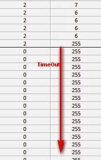
You should also be able to send text to the Android phone by opening up the Serial Monitor on the Arduino IDE (although found this to be somewhat unreliable/unpredictable. I may need to investigate a better way of doing this, but it should work to some capacity (I sometimes find that a couple of letters go missing on transmision).
In this sketch I am using a Bluetooth shield like this one,  and have connected a Grove Chainable RGB LED to it using a Grove Universal 4 Pin Cable.


Arduino Sketch 2: Bluetooth RGB Colour Changer

 1
2
3
4
5
6
7
8
9
10
11
12
13
14
15
16
17
18
19
20
21
22
23
24
25
26
27
28
29
30
31
32
33
34
35
36
37
38
39
40
41
42
43
44
45
46
47
48
49
50
51
52
53
54
55
56
57
58
59
60
61
62
63
64
65
66
67
68
69
70
71
72
73
74
75
76
77
78
79
80
81
82
83
84
85
86
87
88
89
90
91
92
93
94
95
96
97
98
99
100
101
102
103
104
105
106
107
108
109
110
111
112
113
114
115
116
117
118
119
120
121
122
123
124
125
126
127
128
129
130
131
132
133
134
135
136
137
138
139
140
141
142
143
144
145
146
147
148
149
/* This project combines the code from a few different sources.
This project was put together by ScottC on the 15/01/2013
http://arduinobasics.blogspot.com/

Bluetooth slave code by Steve Chang - downloaded from :
http://www.seeedstudio.com/wiki/index.php?title=Bluetooth_Shield

Grove Chainable RGB code can be found here :
http://www.seeedstudio.com/wiki/Grove_-_Chainable_RGB_LED#Introduction

*/

#include <SoftwareSerial.h> //Software Serial Port
#define uint8 unsigned char
#define uint16 unsigned int
#define uint32 unsigned long int

#define RxD 6 // This is the pin that the Bluetooth (BT_TX) will transmit to the Arduino (RxD)
#define TxD 7 // This is the pin that the Bluetooth (BT_RX) will receive from the Arduino (TxD)

#define DEBUG_ENABLED 1

int Clkpin = 9; //RGB LED Clock Pin (Digital 9)
int Datapin = 8; //RGB LED Data Pin (Digital 8)

SoftwareSerial blueToothSerial(RxD,TxD);
/*----------------------SETUP----------------------------*/ void setup() {
Serial.begin(9600); // Allow Serial communication via USB cable to computer (if required)
pinMode(RxD, INPUT); // Setup the Arduino to receive INPUT from the bluetooth shield on Digital Pin 6
pinMode(TxD, OUTPUT); // Setup the Arduino to send data (OUTPUT) to the bluetooth shield on Digital Pin 7
pinMode(13,OUTPUT); // Use onboard LED if required.
setupBlueToothConnection(); //Used to initialise the Bluetooth shield

pinMode(Datapin, OUTPUT); // Setup the RGB LED Data Pin
pinMode(Clkpin, OUTPUT); // Setup the RGB LED Clock pin

}
/*----------------------LOOP----------------------------*/ void loop() {
digitalWrite(13,LOW); //Turn off the onboard Arduino LED
char recvChar;
while(1){
if(blueToothSerial.available()){//check if there's any data sent from the remote bluetooth shield
recvChar = blueToothSerial.read();
Serial.print(recvChar); // Print the character received to the Serial Monitor (if required)

//If the character received = 'r' , then change the RGB led to display a RED colour
if(recvChar=='r'){
Send32Zero(); // begin
DataDealWithAndSend(255, 0, 0); // first node data
Send32Zero(); // send to update data
}

//If the character received = 'g' , then change the RGB led to display a GREEN colour
if(recvChar=='g'){
Send32Zero(); // begin
DataDealWithAndSend(0, 255, 0); // first node data
Send32Zero(); // send to update data
}

//If the character received = 'b' , then change the RGB led to display a BLUE colour
if(recvChar=='b'){
Send32Zero(); // begin
DataDealWithAndSend(0, 0, 255); // first node data
Send32Zero(); // send to update data
}
}

//You can use the following code to deal with any information coming from the Computer (serial monitor)
if(Serial.available()){
recvChar = Serial.read();

//This will send value obtained (recvChar) to the phone. The value will be displayed on the phone.
blueToothSerial.print(recvChar);
}
}
}

//The following code is necessary to setup the bluetooth shield ------copy and paste----------------
void setupBlueToothConnection()
{
blueToothSerial.begin(38400); //Set BluetoothBee BaudRate to default baud rate 38400
blueToothSerial.print("\r\n+STWMOD=0\r\n"); //set the bluetooth work in slave mode
blueToothSerial.print("\r\n+STNA=SeeedBTSlave\r\n"); //set the bluetooth name as "SeeedBTSlave"
blueToothSerial.print("\r\n+STOAUT=1\r\n"); // Permit Paired device to connect me
blueToothSerial.print("\r\n+STAUTO=0\r\n"); // Auto-connection should be forbidden here
delay(2000); // This delay is required.
blueToothSerial.print("\r\n+INQ=1\r\n"); //make the slave bluetooth inquirable
Serial.println("The slave bluetooth is inquirable!");
delay(2000); // This delay is required.
blueToothSerial.flush();
}

//The following code snippets are used update the colour of the RGB LED-----copy and paste------------
void ClkProduce(void){
digitalWrite(Clkpin, LOW);
delayMicroseconds(20);
digitalWrite(Clkpin, HIGH);
delayMicroseconds(20);
}
void Send32Zero(void){
unsigned char i;
for (i=0; i<32; i++){
digitalWrite(Datapin, LOW);
ClkProduce();
}
}

uint8 TakeAntiCode(uint8 dat){
uint8 tmp = 0;
if ((dat & 0x80) == 0){
tmp |= 0x02;
}

if ((dat & 0x40) == 0){
tmp |= 0x01;
}

return tmp;
}
// gray data
void DatSend(uint32 dx){
uint8 i;
for (i=0; i<32; i++){
if ((dx & 0x80000000) != 0){
digitalWrite(Datapin, HIGH);
} else {
digitalWrite(Datapin, LOW);
}

dx <<= 1;
ClkProduce();
}
}
// data processing
void DataDealWithAndSend(uint8 r, uint8 g, uint8 b){
uint32 dx = 0;

dx |= (uint32)0x03 << 30; // highest two bits 1,flag bits
dx |= (uint32)TakeAntiCode(b) << 28;
dx |= (uint32)TakeAntiCode(g) << 26;
dx |= (uint32)TakeAntiCode(r) << 24;

dx |= (uint32)b << 16;
dx |= (uint32)g << 8;
dx |= r;

DatSend(dx);
}


Some GUI Buttons

My aim is to somewhat recreate the experience from a similar project I blogged about (here). However I wanted to have much more control over the GUI. I will start by creating a few buttons, but will later look at making a much more fun/interactive design (hopefully). The following simple Android/Processing sketch will be totally independant of the sketch above, it will be a simple App that will have a few buttons which will change the colour of the background on the phone. Once we get the hang of this, we will incorporate it into our Bluetooth Sketch.
To start off with, we will need to download an Android/Processing library which will allow us to create the buttons that we will use in our App.
Unzip the apwidgets_r44.zip file and put the apwidgets folder into your default Processing sketch "libraries" folder. For more information about installing contributed libraries into you Processing IDE - have a look at this site.
You will need to reboot your Processing IDE before being able to see the "apwidgets" item appear in the Processing IDE's menu,
  • Sketch > Import Library :  Under the "Contributed" list item.
If you cannot see this menu item, then you will need to try again. Make sure you are putting it into the default sketch libraries folder, which may not be in the same folder as the processing IDE. To find out the default sketch location - look here:
  • File > Preferences > Sketchbook location
Ok, now that you have the APWidgets library installed in your Processing IDE, make sure you are still in Andorid Mode, and copy the following sketch into the IDE, and run the program on your device. This sketch borrows heavily from the APWidgets Button example, which can be found here.

Android/Processing Sketch 7: Button Presser
 1
2
3
4
5
6
7
8
9
10
11
12
13
14
15
16
17
18
19
20
21
22
23
24
25
26
27
28
29
30
31
32
33
34
35
36
37
38
39
40
41
42
43
44
45
46
47
48
49
50
51
52
53
54
55
import apwidgets.*;

APWidgetContainer widgetContainer;
APButton redButton, greenButton, blueButton, offButton;
String buttonText="";
int buttonWidth=0;
int buttonHeight=0;
int n=4; //number of buttons
int gap=10; //gap between buttons


void setup() {
buttonWidth=((width/n)-(n*gap));
buttonHeight=(height/2);
widgetContainer = new APWidgetContainer(this); //create new container for widgets
redButton =new APButton((buttonWidth*(n-4)+(gap*1)), gap, buttonWidth, buttonHeight, "RED"); //Create a RED button
greenButton = new APButton((buttonWidth*(n-3)+(gap*2)), gap, buttonWidth, buttonHeight, "GREEN"); //Create a GREEN button
blueButton = new APButton((buttonWidth*(n-2)+(gap*3)), gap, buttonWidth, buttonHeight, "BLUE"); //Create a BLUE button
offButton = new APButton((buttonWidth*(n-1)+(gap*4)), gap, buttonWidth, buttonHeight, "OFF"); //Create a OFF button
widgetContainer.addWidget(redButton); //place red button in container
widgetContainer.addWidget(greenButton); //place green button in container
widgetContainer.addWidget(blueButton);//place blue button in container
widgetContainer.addWidget(offButton);//place off button in container
background(0); //Start with a black background
}


void draw() {
//Change the text based on the button being pressed.
text(buttonText, 10, buttonHeight+(buttonHeight/2));
}


//onClickWidget is called when a widget is clicked/touched
void onClickWidget(APWidget widget) {

if (widget == redButton) { //if the red button was clicked
buttonText="RED";
background(255, 0, 0);
}
else if (widget == greenButton) { //if the green button was clicked
buttonText="GREEN";
background(0, 255, 0);
}
else if (widget == blueButton) { //if the blue button was clicked
buttonText="BLUE";
background(0, 0, 255);
}
else if (widget == offButton) { //if the off button was clicked
buttonText="OFF";
background(0);
}
}

The sketch creates 4 buttons, one for Red, Green, Blue and Off. In this example, we use the onClickWidget() method to deal with button_click events, which we use to change the colour of the background.  I forgot to include the following line in the setup() method:
  • orientation(LANDSCAPE);
This will force the application to go into landscape mode, which is what I intended.


Bluetooth Buttons : Adding Buttons to the Bluetooth project

We will now incorporate the Buttons sketch into our Bluetooth project so that when we press a button, it will send a letter to the Arduino via Bluetooth. The letter will be used by the Arduino to decide what colour to display on the Chainable RGB LED. We will still keep the previous functionality of changing the LED to RED when a successful Input/OutputStream is created, because this will be the signal to suggest that it is now ok to press the buttons (and we should see it work).

Here is the updated Android/Processing sketch

Android/Processing Sketch 8: Bluetooth App1

 1
2
3
4
5
6
7
8
9
10
11
12
13
14
15
16
17
18
19
20
21
22
23
24
25
26
27
28
29
30
31
32
33
34
35
36
37
38
39
40
41
42
43
44
45
46
47
48
49
50
51
52
53
54
55
56
57
58
59
60
61
62
63
64
65
66
67
68
69
70
71
72
73
74
75
76
77
78
79
80
81
82
83
84
85
86
87
88
89
90
91
92
93
94
95
96
97
98
99
100
101
102
103
104
105
106
107
108
109
110
111
112
113
114
115
116
117
118
119
120
121
122
123
124
125
126
127
128
129
130
131
132
133
134
135
136
137
138
139
140
141
142
143
144
145
146
147
148
149
150
151
152
153
154
155
156
157
158
159
160
161
162
163
164
165
166
167
168
169
170
171
172
173
174
175
176
177
178
179
180
181
182
183
184
185
186
187
188
189
190
191
192
193
194
195
196
197
198
199
200
201
202
203
204
205
206
207
208
209
210
211
212
213
214
215
216
217
218
219
220
221
222
223
224
225
226
227
228
229
230
231
232
233
234
235
236
237
238
239
240
241
242
243
244
245
246
247
248
249
250
251
252
253
254
255
256
257
258
259
260
261
262
263
264
265
266
267
268
269
270
271
272
273
274
275
276
277
278
279
280
281
282
283
284
285
286
287
288
289
290
291
292
293
294
295
296
297
298
299
300
301
302
303
304
305
306
307
308
309
310
311
312
313
314
315
316
317
318
319
320
321
322
323
324
325
326
327
328
329
330
331
332
333
334
335
336
337
338
339
340
341
342
343
344
345
346
347
348
349
350
351
352
353
354
355
356
357
358
359
360
361
362
363
364
365
366
367
368
369
370
371
372
373
374
375
376
377
378
379
380
381
382
383
384
385
386
387
388
389
390
391
392
393
394
395
396
397
398
399
400
401
402
403
404
/* BluetoothApp1: Written by ScottC on 25 March 2013 using 
Processing version 2.0b8
Tested on a Samsung Galaxy SII, with Android version 2.3.4
Android ADK - API 10 SDK platform
Apwidgets version: r44 */

import android.content.BroadcastReceiver;
import android.content.Context;
import android.content.Intent;
import android.content.IntentFilter;
import android.widget.Toast;
import android.view.Gravity;
import android.bluetooth.BluetoothAdapter;
import android.bluetooth.BluetoothDevice;

import java.util.UUID;
import java.io.IOException;
import java.io.InputStream;
import java.io.OutputStream;
import android.os.Handler;
import android.os.Message;
import android.util.Log;

import android.bluetooth.BluetoothServerSocket;
import android.bluetooth.BluetoothSocket;
import apwidgets.*;
public BluetoothSocket scSocket;


//Used for the GUI**************************************
APWidgetContainer widgetContainer;
APButton redButton, greenButton, blueButton, offButton;
String buttonText="";
int buttonWidth=0;
int buttonHeight=0;
int n=4; //number of buttons
int gap=10; //gap between buttons

boolean foundDevice=false; //When true, the screen turns green.
boolean BTisConnected=false; //When true, the screen turns purple.
String serverName = "ArduinoBasicsServer";

// Message types used by the Handler
public static final int MESSAGE_WRITE = 1;
public static final int MESSAGE_READ = 2;
String readMessage="";

//Used to send bytes to the Arduino
SendReceiveBytes sendReceiveBT=null;

//Get the default Bluetooth adapter
BluetoothAdapter bluetooth = BluetoothAdapter.getDefaultAdapter();

/*The startActivityForResult() within setup() launches an
Activity which is used to request the user to turn Bluetooth on.
The following onActivityResult() method is called when this
Activity exits. */
@Override
protected void onActivityResult(int requestCode, int resultCode, Intent data) {
if (requestCode==0) {
if (resultCode == RESULT_OK) {
ToastMaster("Bluetooth has been switched ON");
}
else {
ToastMaster("You need to turn Bluetooth ON !!!");
}
}
}


/* Create a BroadcastReceiver that will later be used to
receive the names of Bluetooth devices in range. */
BroadcastReceiver myDiscoverer = new myOwnBroadcastReceiver();


/* Create a BroadcastReceiver that will later be used to
identify if the Bluetooth device is connected */
BroadcastReceiver checkIsConnected = new myOwnBroadcastReceiver();


// The Handler that gets information back from the Socket
private final Handler mHandler = new Handler() {
@Override
public void handleMessage(Message msg) {
switch (msg.what) {
case MESSAGE_WRITE:
//Do something when writing
break;
case MESSAGE_READ:
//Get the bytes from the msg.obj
byte[] readBuf = (byte[]) msg.obj;
// construct a string from the valid bytes in the buffer
readMessage = new String(readBuf, 0, msg.arg1);
break;
}
}
};


void setup() {
orientation(LANDSCAPE);

//Setup GUI********************************
buttonWidth=((width/n)-(n*gap));
buttonHeight=(height/2);
widgetContainer = new APWidgetContainer(this); //create new container for widgets
redButton =new APButton((buttonWidth*(n-4)+(gap*1)), gap, buttonWidth, buttonHeight, "RED"); //Create a RED button
greenButton = new APButton((buttonWidth*(n-3)+(gap*2)), gap, buttonWidth, buttonHeight, "GREEN"); //Create a GREEN button
blueButton = new APButton((buttonWidth*(n-2)+(gap*3)), gap, buttonWidth, buttonHeight, "BLUE"); //Create a BLUE button
offButton = new APButton((buttonWidth*(n-1)+(gap*4)), gap, buttonWidth, buttonHeight, "OFF"); //Create a OFF button
widgetContainer.addWidget(redButton); //place red button in container
widgetContainer.addWidget(greenButton); //place green button in container
widgetContainer.addWidget(blueButton);//place blue button in container
widgetContainer.addWidget(offButton);//place off button in container
background(0); //Start with a black background

/*IF Bluetooth is NOT enabled, then ask user permission to enable it */
if (!bluetooth.isEnabled()) {
Intent requestBluetooth = new Intent(BluetoothAdapter.ACTION_REQUEST_ENABLE);
startActivityForResult(requestBluetooth, 0);
}

/*If Bluetooth is now enabled, then register a broadcastReceiver to report any
discovered Bluetooth devices, and then start discovering */
if (bluetooth.isEnabled()) {
registerReceiver(myDiscoverer, new IntentFilter(BluetoothDevice.ACTION_FOUND));
registerReceiver(checkIsConnected, new IntentFilter(BluetoothDevice.ACTION_ACL_CONNECTED));

//Start bluetooth discovery if it is not doing so already
if (!bluetooth.isDiscovering()) {
bluetooth.startDiscovery();
}
}
}


void draw() {
//Display a green screen if a device has been found,
//Display a purple screen when a connection is made to the device
if (foundDevice) {
if (BTisConnected) {
background(170, 50, 255); // purple screen
}
else {
background(10, 255, 10); // green screen
}
}


//Change the text based on the button being pressed.
text(buttonText, 10, buttonHeight+(buttonHeight/2));

//Display anything received from Arduino
text(readMessage, 10, buttonHeight+(buttonHeight/2)+30);
}


/* This BroadcastReceiver will display discovered Bluetooth devices */
public class myOwnBroadcastReceiver extends BroadcastReceiver {
ConnectToBluetooth connectBT;

@Override
public void onReceive(Context context, Intent intent) {
String action=intent.getAction();
ToastMaster("ACTION:" + action);

//Notification that BluetoothDevice is FOUND
if (BluetoothDevice.ACTION_FOUND.equals(action)) {
//Display the name of the discovered device
String discoveredDeviceName = intent.getStringExtra(BluetoothDevice.EXTRA_NAME);
ToastMaster("Discovered: " + discoveredDeviceName);

//Display more information about the discovered device
BluetoothDevice discoveredDevice = intent.getParcelableExtra(BluetoothDevice.EXTRA_DEVICE);
ToastMaster("getAddress() = " + discoveredDevice.getAddress());
ToastMaster("getName() = " + discoveredDevice.getName());

int bondyState=discoveredDevice.getBondState();
ToastMaster("getBondState() = " + bondyState);

String mybondState;
switch(bondyState) {
case 10:
mybondState="BOND_NONE";
break;
case 11:
mybondState="BOND_BONDING";
break;
case 12:
mybondState="BOND_BONDED";
break;
default:
mybondState="INVALID BOND STATE";
break;
}
ToastMaster("getBondState() = " + mybondState);

//Change foundDevice to true which will make the screen turn green
foundDevice=true;

//Connect to the discovered bluetooth device (SeeedBTSlave)
if (discoveredDeviceName.equals("SeeedBTSlave")) {
ToastMaster("Connecting you Now !!");
unregisterReceiver(myDiscoverer);
connectBT = new ConnectToBluetooth(discoveredDevice);
//Connect to the the device in a new thread
new Thread(connectBT).start();
}
}

//Notification if bluetooth device is connected
if (BluetoothDevice.ACTION_ACL_CONNECTED.equals(action)) {
ToastMaster("CONNECTED _ YAY");
int counter=0;
while (scSocket==null) {
//do nothing
}
ToastMaster("scSocket" + scSocket);
BTisConnected=true; //turn screen purple
if (scSocket!=null) {
sendReceiveBT = new SendReceiveBytes(scSocket);
new Thread(sendReceiveBT).start();
String red = "r";
byte[] myByte = stringToBytesUTFCustom(red);
sendReceiveBT.write(myByte);
}
}
}
}

public static byte[] stringToBytesUTFCustom(String str) {
char[] buffer = str.toCharArray();
byte[] b = new byte[buffer.length << 1];
for (int i = 0; i < buffer.length; i++) {
int bpos = i << 1;
b[bpos] = (byte) ((buffer[i]&0xFF00)>>8);
b[bpos + 1] = (byte) (buffer[i]&0x00FF);
}
return b;
}

public class ConnectToBluetooth implements Runnable {
private BluetoothDevice btShield;
private BluetoothSocket mySocket = null;
private UUID uuid = UUID.fromString("00001101-0000-1000-8000-00805F9B34FB");

public ConnectToBluetooth(BluetoothDevice bluetoothShield) {
btShield = bluetoothShield;
try {
mySocket = btShield.createRfcommSocketToServiceRecord(uuid);
}
catch(IOException createSocketException) {
//Problem with creating a socket
Log.e("ConnectToBluetooth", "Error with Socket");
}
}

@Override
public void run() {
/* Cancel discovery on Bluetooth Adapter to prevent slow connection */
bluetooth.cancelDiscovery();

try {
/*Connect to the bluetoothShield through the Socket. This will block
until it succeeds or throws an IOException */
mySocket.connect();
scSocket=mySocket;
}
catch (IOException connectException) {
Log.e("ConnectToBluetooth", "Error with Socket Connection");
try {
mySocket.close(); //try to close the socket
}
catch(IOException closeException) {
}
return;
}
}

// Will allow you to get the socket from this class
public BluetoothSocket getSocket() {
return mySocket;
}

/* Will cancel an in-progress connection, and close the socket */
public void cancel() {
try {
mySocket.close();
}
catch (IOException e) {
}
}
}


private class SendReceiveBytes implements Runnable {
private BluetoothSocket btSocket;
private InputStream btInputStream = null;
;
private OutputStream btOutputStream = null;
String TAG = "SendReceiveBytes";

public SendReceiveBytes(BluetoothSocket socket) {
btSocket = socket;
try {
btInputStream = btSocket.getInputStream();
btOutputStream = btSocket.getOutputStream();
}
catch (IOException streamError) {
Log.e(TAG, "Error when getting input or output Stream");
}
}

public void run() {
byte[] buffer = new byte[1024]; // buffer store for the stream
int bytes; // bytes returned from read()

// Keep listening to the InputStream until an exception occurs
while (true) {
try {
// Read from the InputStream
bytes = btInputStream.read(buffer);
// Send the obtained bytes to the UI activity
mHandler.obtainMessage(MESSAGE_READ, bytes, -1, buffer)
.sendToTarget();
}
catch (IOException e) {
Log.e(TAG, "Error reading from btInputStream");
break;
}
}
}

/* Call this from the main activity to send data to the remote device */
public void write(byte[] bytes) {
try {
btOutputStream.write(bytes);
}
catch (IOException e) {
Log.e(TAG, "Error when writing to btOutputStream");
}
}

/* Call this from the main activity to shutdown the connection */
public void cancel() {
try {
btSocket.close();
}
catch (IOException e) {
Log.e(TAG, "Error when closing the btSocket");
}
}
}


/* My ToastMaster function to display a messageBox on the screen */
void ToastMaster(String textToDisplay) {
Toast myMessage = Toast.makeText(getApplicationContext(),
textToDisplay,
Toast.LENGTH_SHORT);
myMessage.setGravity(Gravity.CENTER, 0, 0);
myMessage.show();
}


//onClickWidget is called when a widget is clicked/touched
void onClickWidget(APWidget widget) {
String sendLetter = "";

//Disable the previous Background colour changers
foundDevice=false;
BTisConnected=false;

if (widget == redButton) { //if the red button was clicked
buttonText="RED";
background(255, 0, 0);
sendLetter = "r";
}
else if (widget == greenButton) { //if the green button was clicked
buttonText="GREEN";
background(0, 255, 0);
sendLetter = "g";
}
else if (widget == blueButton) { //if the blue button was clicked
buttonText="BLUE";
background(0, 0, 255);
sendLetter = "b";
}
else if (widget == offButton) { //if the off button was clicked
buttonText="OFF";
background(0);
sendLetter = "x";
}

byte[] myByte = stringToBytesUTFCustom(sendLetter);
sendReceiveBT.write(myByte);
}
The sketch above has been thrown together without much planning or consideration for code efficiency. It was deliberately done this way so that you could see and follow the incremental approach used to create this Android/Processing Bluetooth App. I will do my best to rewrite and simplify some of the code, however, I don't anticipate the final sketch will be a short script.
You should have noticed that I included a fourth button called an "off" button. This will turn off the RGB led. However, the Arduino code in its current format does not know what to do with an 'x'. So we will update the sketch as follows:

Arduino Sketch 3: Bluetooth RGB Colour Changer (with OFF option)

 1
2
3
4
5
6
7
8
9
10
11
12
13
14
15
16
17
18
19
20
21
22
23
24
25
26
27
28
29
30
31
32
33
34
35
36
37
38
39
40
41
42
43
44
45
46
47
48
49
50
51
52
53
54
55
56
57
58
59
60
61
62
63
64
65
66
67
68
69
70
71
72
73
74
75
76
77
78
79
80
81
82
83
84
85
86
87
88
89
90
91
92
93
94
95
96
97
98
99
100
101
102
103
104
105
106
107
108
109
110
111
112
113
114
115
116
117
118
119
120
121
122
123
124
125
126
127
128
129
130
131
132
133
134
135
136
137
138
139
140
141
142
143
144
145
146
147
148
149
150
151
152
153
154
155
156
157
158
159
160
161
162
163
164
165
166
167
168
169
170
/* This project combines the code from a few different sources.
This project was put together by ScottC on the 15/01/2013
http://arduinobasics.blogspot.com/

Bluetooth slave code by Steve Chang - downloaded from :
http://www.seeedstudio.com/wiki/index.php?title=Bluetooth_Shield

Grove Chainable RGB code can be found here :
http://www.seeedstudio.com/wiki/Grove_-_Chainable_RGB_LED#Introduction

Updated on 25 March 2013: Receive 'x' to turn off RGB LED.

*/

#include <SoftwareSerial.h> //Software Serial Port

#define uint8 unsigned char
#define uint16 unsigned int
#define uint32 unsigned long int

#define RxD 6 // This is the pin that the Bluetooth (BT_TX) will transmit to the Arduino (RxD)
#define TxD 7 // This is the pin that the Bluetooth (BT_RX) will receive from the Arduino (TxD)

#define DEBUG_ENABLED 1

int Clkpin = 9; //RGB LED Clock Pin (Digital 9)
int Datapin = 8; //RGB LED Data Pin (Digital 8)

SoftwareSerial blueToothSerial(RxD, TxD);


/*----------------------SETUP----------------------------*/
void setup() {
Serial.begin(9600); // Allow Serial communication via USB cable to computer (if required)
pinMode(RxD, INPUT); // Setup the Arduino to receive INPUT from the bluetooth shield on Digital Pin 6
pinMode(TxD, OUTPUT); // Setup the Arduino to send data (OUTPUT) to the bluetooth shield on Digital Pin 7
pinMode(13, OUTPUT); // Use onboard LED if required.
setupBlueToothConnection(); //Used to initialise the Bluetooth shield

pinMode(Datapin, OUTPUT); // Setup the RGB LED Data Pin
pinMode(Clkpin, OUTPUT); // Setup the RGB LED Clock pin
}


/*----------------------LOOP----------------------------*/
void loop() {
digitalWrite(13, LOW); //Turn off the onboard Arduino LED
char recvChar;
while (1) {
if (blueToothSerial.available()) {//check if there's any data sent from the remote bluetooth shield
recvChar = blueToothSerial.read();
Serial.print(recvChar); // Print the character received to the Serial Monitor (if required)

//If the character received = 'r' , then change the RGB led to display a RED colour
if (recvChar=='r') {
Send32Zero(); // begin
DataDealWithAndSend(255, 0, 0); // first node data
Send32Zero(); // send to update data
}

//If the character received = 'g' , then change the RGB led to display a GREEN colour
if (recvChar=='g') {
Send32Zero(); // begin
DataDealWithAndSend(0, 255, 0); // first node data
Send32Zero(); // send to update data
}

//If the character received = 'b' , then change the RGB led to display a BLUE colour
if (recvChar=='b') {
Send32Zero(); // begin
DataDealWithAndSend(0, 0, 255); // first node data
Send32Zero(); // send to update data
}

//If the character received = 'x' , then turn RGB led OFF
if (recvChar=='x') {
Send32Zero(); // begin
DataDealWithAndSend(0, 0, 0); // first node data
Send32Zero(); // send to update data
}
}

//You can use the following code to deal with any information coming from the Computer (serial monitor)
if (Serial.available()) {
recvChar = Serial.read();

//This will send value obtained (recvChar) to the phone. The value will be displayed on the phone.
blueToothSerial.print(recvChar);
}
}
}


//The following code is necessary to setup the bluetooth shield ------copy and paste----------------
void setupBlueToothConnection()
{
blueToothSerial.begin(38400); //Set BluetoothBee BaudRate to default baud rate 38400
blueToothSerial.print("\r\n+STWMOD=0\r\n"); //set the bluetooth work in slave mode
blueToothSerial.print("\r\n+STNA=SeeedBTSlave\r\n"); //set the bluetooth name as "SeeedBTSlave"
blueToothSerial.print("\r\n+STOAUT=1\r\n"); // Permit Paired device to connect me
blueToothSerial.print("\r\n+STAUTO=0\r\n"); // Auto-connection should be forbidden here
delay(2000); // This delay is required.
blueToothSerial.print("\r\n+INQ=1\r\n"); //make the slave bluetooth inquirable
Serial.println("The slave bluetooth is inquirable!");
delay(2000); // This delay is required.
blueToothSerial.flush();
}


//The following code snippets are used update the colour of the RGB LED-----copy and paste------------
void ClkProduce(void) {
digitalWrite(Clkpin, LOW);
delayMicroseconds(20);
digitalWrite(Clkpin, HIGH);
delayMicroseconds(20);
}
void Send32Zero(void) {
unsigned char i;
for (i=0; i<32; i++) {
digitalWrite(Datapin, LOW);
ClkProduce();
}
}


uint8 TakeAntiCode(uint8 dat) {
uint8 tmp = 0;
if ((dat & 0x80) == 0) {
tmp |= 0x02;
}

if ((dat & 0x40) == 0) {
tmp |= 0x01;
}
return tmp;
}


// gray data
void DatSend(uint32 dx) {
uint8 i;
for (i=0; i<32; i++) {
if ((dx & 0x80000000) != 0) {
digitalWrite(Datapin, HIGH);
}
else {
digitalWrite(Datapin, LOW);
}
dx <<= 1;
ClkProduce();
}
}

// data processing
void DataDealWithAndSend(uint8 r, uint8 g, uint8 b) {
uint32 dx = 0;

dx |= (uint32)0x03 << 30; // highest two bits 1,flag bits
dx |= (uint32)TakeAntiCode(b) << 28;
dx |= (uint32)TakeAntiCode(g) << 26;
dx |= (uint32)TakeAntiCode(r) << 24;

dx |= (uint32)b << 16;
dx |= (uint32)g << 8;
dx |= r;

DatSend(dx);
}


Well that concludes part 3.
Part 4 is a summary of the finished project with videos, screenshots, parts used etc.
I hope you found this tutorial useful. I would love to receive any advice on how I could improve these tutorials (please put your recommendations in comments below).

Reason for this Project:
While there are quite a few people creating Android/Arduino projects, I have not been able to find many that show how these are being accomplished using the Android/Processing IDE, and even less on how they are using Bluetooth in their Android/Processing projects. I hope my piecing of information will spark some creative Bluetooth projects of your own.


PART 4: Navigate here.