What more can I do (or, more importantly, have the students do with the Capacitive sensing with op amps?
The circuit that I gave in that post has several parameters. Perhaps the students should try predicting what happens when they are adjusted.
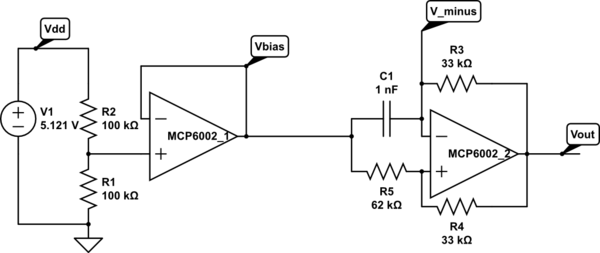
Op amp multivibrator. The first op amp is just to set up a virtual ground halfway between the power rails. The second op amp does the oscillating (at about 8.12 kHz for these components). Circuit drawn with CircuitLab, which is not capable of simulating it.
For example, what happens if Vbias is raised or lowered? What is the effect of changing each of the resistors? How can we optimize the circuit for easy, reliable detection of touches with an Arduino pulseIn() measurement?
If we pretend that the output is a rail-to-rail square wave (ignoring the slew rate limitation), analysis is pretty easy.
 .
.
- If the output is low, then
 and Vminus is higher than that, but dropping.
- If the output is high, then
 and Vminus is lower than that, but rising.
If we define  , we can simplify further and say that Vminus swings between two threshold voltages:
  and
and  .
.
The discharging curve is simply  , where
  , so it takes
  to discharge to the other threshold.
The charging curve is  , and so it takes
  . That is,
  .
.
If we want a symmetric waveform, we need to have  , which in turn requires
  . Raising Vbias makes the low part of the output waveform shorter and the high part longer. Conversely, lowering Vbias makes the low part longer and the high part shorter.
The total period is  . If we set Vbias to Vdd/2, then we can simplify further to
  .
.
The sum R4+R5 only affects the amount of current that the Vbias supply has to provide, but it is probably a good idea to make it fairly large, and to add a bypass capacitor to Vbias, to prevent noise coupling though the bias supply.
When using pulseIn() on the Arduino to measure the capacitance C1, we want to have a large change in the pulse duration (to avoid quantization effects from reporting the duration in μsec), which means a large value for R3. That is limited by the problem of picking up 60Hz noise if the input impedance is too high.
We can also tweak r=R5/R4 a little, to make the period a larger multiple of τ, limited by the problem of noise if we get the thresholds too close to the rails.
Since pulseIn() only measures one part of the waveform (the low part or the high part), we could also tweak the bias voltage to lengthen just that part of the waveform, for example, dropping Vbias to Vdd/4 to length the low part. We again have to be careful not to get the threshold too close to the rails. If we are lowering Vbias, then the threshold to watch is  . If we fix
  as low as we’re willing to make it, then should we make Vbias low or r high? The number we are trying to maximize is the discharge time
  , with the constraint that
  . At equality, we have to maximize
  , which is achieved by making r as large as possible. Of course, that would mean raising Vbias, which would run us into trouble with noise at the other threshold. In general, it seems like the symmetric waveform with Vbias=Vdd/2 gives us the best noise margins.
Next step: how do we either slow down the oscillator or clean up the waveform enough to get a good signal to feed into the Arduino?
I tried increasing both R1 and R5, while decreasing R4, as shown below.

Modified circuit for longer period. C1 is just the stray capacitance of the touch sensor, with no deliberately added capacitance.
This circuit oscillates with a frequency of 35.66 kHz (period of about 28 µsec )when the touch sensor is not touched, which is slow enough that the signal runs from rail to rail. Touching the sensor drops the frequency to 20kHz or less (period of 50 µsec or more). Since r=5.556, the expected period is 4.988 τ, or 0.4988 µsec/pF C1. The period is consistent with a stray capacitance of 56 pF, increasing to over 100 pF when the sensor is touched. There is a lot of jitter in the lower-frequency signal, probably due to some coupling of 60 Hz noise into the system. A 1nF capacitor for C1 gives a frequency of 1660Hz (602 µsec, which is more than the expected 500 µsec), 47nF gives 34.65 Hz (28.86 msec, not the expected 23.44 msec). Why am I consistently 25% off?
The change of 20 µsec or more in the period (10 µsec or more in the half period) should be easily detectable with one pulseIn() measurement on the Arduino. The following code seems to work fairly well, with a light touch causing the LED to flash (right on the edge of detection) and a firmer touch giving a steady reading.
// Capacitive sensor switch
// Thu Jul 12 21:36:42 PDT 2012 Kevin Karplus

// To use, connect the output of the op-amp oscillator to
// pin CAP_PIN on the Arduino.
// The code turns on the LED on pin 13 when a touch is sensed.

// The Arduino measures the width of one LOW pulse on pin CAP_PIN.
// The LED is turned on if the pulse width is more than min_pulse_usec

// pin that oscillator output connected to
#define CAP_PIN (2)

// time (in milliseconds) to wait after a change in state before
// testing input again
#define DEBOUNCE_MSEC (100)

static uint8_t was_on;	// stored state of LED, for detecting transition

static uint16_t min_pulse_usec=5;
// min pulse width (in  microseconds) for detecting a touch

void setup(void)
{
    was_on=0;
    pinMode(CAP_PIN,INPUT);
    pinMode(13, OUTPUT);

    // assuming that the touch sensor is not touched when resetting,
    // find the maximum typical value for untouched sensor
    for (uint8_t i=0; i<10; i++)
    {   long pulse=pulseIn(CAP_PIN,LOW);
        if (pulse>min_pulse_usec)
	{    min_pulse_usec =pulse;
	}
    }
    min_pulse_usec += 2;	// add some room for noise
}

void loop(void)
{
    uint8_t on = pulseIn(CAP_PIN,LOW) >= min_pulse_usec;
    digitalWrite(13, on);
    if (on!=was_on)
    {   delay(DEBOUNCE_MSEC);
        was_on=on;
    }
}
Filed under:
Circuits course Tagged:
Arduino,
bioengineering,
capacitive touch sensor,
circuits,
course design,
op amp,
sensors,
teaching 


 , where the time constant τ=R3 C1. For the values of R4 and R5 here, the charge time should be 1.560 τ, and the period 3.119 τ. With the given values of R3 and C1, this should be a period of 102.9 µsec, or a frequency of 9.7 kHz. I’m measuring 8.1 kHz, not 9.7 kHz, but I think that the discrepancy is due to the slew rate limitations (which add about 12 µsec to the period) and possibly stray capacitance. With C1=47 nF, the frequency is 203.6 Hz, when the calculation says it should be 206.7 Hz, well within the accuracy of the components.
