

Capacitive sensing with op amps
I’m not very happy with the lab exercise in Capacitive sensing. The basic design questions are good:
- What capacitance do we add by touching something?
- What frequency should the oscillator run at without the touch?
- What % change in frequency can we detect reliably? How will we do that detection?
but I’m not happy with my choice of an LM555 chip for the oscillator. It is a fine choice for many purposes, and a good chip for students and hobbyists to learn about, but the Fairchild Semiconductor LM 555 data sheet does not do a good job of explaining how the chip works nor exactly what the logic function is for triggering the flip-flop. As a result, students will probably end up just copying the astable circuit without really understanding it.
I think I would prefer to have them use an op-amp multi-vibrator circuit. It can’t quite be modeled with only linear op amps, as it relies on clipping of the output to get nearly a square wave.
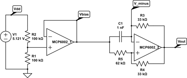
Op amp multivibrator. The first op amp is just to set up a virtual ground halfway between the power rails. The second op amp does the oscillating (at about 8.12 kHz for these components). Circuit drawn with CircuitLab, which is not capable of simulating it.
The op-amp multivibrator is a simple design. When the output is high, C1 is charged until V_minus is higher than the positive input of the op amp (about 34.7% of the way from Vbias to Vout=Vdd). Then the output goes low (taking about 6µsec, limited by the slew rate of the op amp), and the capacitor discharges until it is below the positive input (about 65.3% of the way from Vbias to Vout=0 with these values for R4 and R5). So Vminus swings from (1-0.6526) Vbias = 0.1737 Vdd to Vbias+0.6526(Vdd-Vbias)=0.8263Vdd. The time it takes to charge or discharge should be about 
Connecting the foil-and-plastic-wrap sensor to Vminus adds a little stray capacitance, dropping the frequency to 8.01 kHz. Touching the sensor drops the frequency to 7.5 kHz–7.7 kHz, adding about 5 µsec–8.5 µsec to the period, consistent with adding about 50pF – 83 pF to C1. This is a little smaller than the 163 pF that I estimated using the parallel-plate model in Capacitive sensing, but consistent with my measurements using the LM555 circuits.
I can get a much stronger effect if I remove C1 from the circuit, and use only stray capacitance. The period drops to about 6.2 µsec (roughly 160 kHz), but (because of the slew rate limitations of the op amp) is not full scale and is essentially a triangle wave. Touching the sensor reduces the frequency to about 35 kHz – 45 kHZ, an increase of 16 µsec – 22 µsec in period, consistent with an additional capacitance of 155 pF – 220 pF, which is about what was predicted by the parallel plate model. I’m a little reluctant to put this signal into an Arduino board, though, as the no-touch signal spends most of its time in the non-digital region between high and low, and only barely crosses the thresholds that would allow the ATMega328 chip to detect the signal.
One interesting idea would be to take advantage of the change in amplitude of the oscillation to make an all-analog touch detector. I’m afraid that would not be very robust, though, as an increase in the period of only 12 µsec is enough to make the oscillation full scale.
Filed under: Circuits course Tagged: Arduino, bioengineering, capacitive touch sensor, circuits, course design, LM555, op amp, sensors, teaching


[original story: Gas station without pumps]