Posts with «arduino» label

Video mixing chess games on tv in Norway using Ethernet Shield

Heidi Røneid with an Arduino Ethernet microprocessor. (Photo: Tore Zakariassen, NRK)

When The Norwegian Broadcasting (NRK) planned the television broadcast of the Chess Olympiad 2014 in Tromsø, Norway, they encountered a challenge: how to mix video, graphics and the results of many ongoing chess games simultaneously, requiring 16 cameras for the games going on at the same time?

On their blog you can find a long and nice post about how they found the solution using Arduino Uno, Arduino Ethernet Shield and the library for Arduino to control such Atem switchers written by Kasper Skårhøj:

At first, the idea was to use a computer with a webcam for each of the 16 games, then mix video images, background animation and results in software on each of them.

Afterwards the finished mix of images would be streamed to separate channels in our web player, so that the online audience would be able to choose which game they wanted to follow. This solution would also provide our outside broadcasting van (OB van) with 16 finished video sources composed of video, graphics and results. This would make the complex job of mixing all video signals much easier.

After thorough thinking we came to the conclusion that for our web-audience, it would be better to skip the stream of individual games, and spend our resources on building websites that could present all games in the championship via HTML in real time. This would also give the audience the opportunity to scroll back and forth in the moves and recall all the previous games in the championship. We started working on it immediately, and you can find the result on our website nrk.no/sjakk.

Arduino Blog 28 Aug 19:14
arduino  chess  ethernet  featured  games  norway  shield  tv  

How the Makers at Nomiku Are Moving Manufacturing Into The Bay Area

This is a series that will document Nomiku’s journey into lean manufacturing in America through the conversations of the founding team: Lisa, Abe, and Bam. We will update the series as our adventure in building our high-tech device that lets people cook with the cloud continues. As we enter uncharted […]

Read more on MAKE

Gemma-Powered NeoPixel Sound Reactive Drums

This tutorial from Adafruit shows how to create a custom interactive drum set that lights up with sound. It uses a mic amp sensor that is connected to a miniature Arduino Gemma board to detect when the instrument is being hit by the sticks. Neopixels then illuminate into a range of colors creating a beautifully synced up music presentation.

The container that houses the electronics is 3D printed. The entire circuit is integrated into the snare, mid-tom, hi-tom and a drum kick. All the code and step-by-step instructions can be found on Adafruit’s website. Now imagine something like this being packed up in a suitcase and carried from venue to venue as an up-and-coming band travels from state to state on tour; especially at Drum n’ Bass raves or electronic based music festivals. A video of the kit being used is below.


Filed under: musical hacks
Hack a Day 27 Aug 03:00

The ChalkJET Writing Machine

“Way back” in 2009, students in the UC Berkley “ME 102″ class came up with this excellent automatic chalk-spraying machine. It uses 8 cans of spray-chalk to spray the message of your choosing onto the sidewalk or street as you push it along. This device is controlled by two Arduino […]

Read more on MAKE

A Virtual Touchscreen (3D Ultrasonic Radar)

Producing items onto a screen simply by touching the air is a marvelous thing. One way to accomplish this involves four HC-SR04 ultrasonic sensor units that transmit data through an Arduino into a Linux computer. The end result is a virtual touchscreen that can made at home.

The software of this device was developed by [Anatoly] who translated hand gestures into actionable commands. The sensors attached to the Arduino had a an approximate scanning range of 3m, and the ultrasonic units were modified to broadcast an analog signal at 40 kHz. There were a few limitations with the original hardware design as [Anatoly] stated in the post. For example, at first, only one unit was transmitting at a time, so there was no way the Arduino could identify two objects on the same sphere. However, [Anatoly] updated the blog with a 2nd post showing that sensing multiple items at once could be done. Occasionally, the range would be finicky when dealing small items like pens. But besides that, it seemed to work pretty well.

Additional technical specifications can be found on [Anatoly]‘s blog and videos of the system working can be seen after the break.


[Thanks for the tip João!]


Filed under: Tech Hacks

The Counter-Strike Airsoft Robot

[Jon] and his brother converted an RC car into a robot that can fire airsoft pellets into the air. The little motorized vehicle was disassembled and a handheld was attached to the top. A pulling mechanism was put in place and a safety procedure was added to make sure no accidents occurred.

An Arduino was used to get the servo working, and a chassis stand was created to hold the handle. The setup was then tested at this point, and a Raspberry Pi server was configured to install a motion sensing camera that would act as the eyes for the robot. Once everything was in place, the wheels hit the ground and the vehicle was able to move around, positioning itself to aim the servos at a designated target. Footage was transmitted via the web showing what the robot was looking at.

A video of the remote-controlled counter-strike robot can be seen after the break. You could consider this your toy army. That makes this one your toy air force.


Filed under: toy hacks
Hack a Day 24 Aug 15:01

Stewart Platform Ball Bearing Balancer

For their Mechanical Engineering senior design project at San Jose State University, [Tyler Kroymann] and [Robert Dee] designed and built a racing motion simulator. Which is slightly out of the budget of most hackers, so before they went full-scale, a more affordable Arduino powered Stewart platform proof of concept was built. Stewart platforms typically use six electric or hydraulic linear actuators to provide motion in six degrees of freedom (6 DOF), surge (X), sway (Y), heave (Z), pitch, roll, and yaw. With a simple software translation matrix, to account for the angular displacement of the servo arm, you can transform the needed linear motions into PWM signals for standard hobby servos.

The 6 DOF platform, with the addition of a resistive touch screen, also doubled as a side project for their mechatronic control systems class. However, in this configuration the platform was constrained to just pitch and roll. The Arduino reads the resistive touch screen and registers the ball bearing’s location. Then a PID compares this to the target location generating an error vector. The error vector is used to find an inverse kinematic solution which causes the actuators to move the ball towards the target location. This whole process is repeated 50 times a second. The target location can be a pre-programmed or controlled using the analog stick on a Wii nunchuck.

Watch the ball bearing seek the target location after the break.

Thanks to [Toby] for sending in this tip.

We at Hackaday look forward to the real life implementation of Marble Madness!

Need help Demystifying PID Control? Or perhaps you would like to build your own Stewart Platform?


Filed under: Arduino Hacks, robots hacks

New Project: Smart Remote Control

Combine the Arduino Yún with a simple solderless breadboard circuit to create a homemade 'universal' remote control that you can navigate with your laptop or smartphone.

Read more on MAKE

A Custom Bicycle Dashboard

If you’re not satisfied with the lightweight digital speedometer that you can buy at your local bike shop, why not build your own bicycle dashboard using various electrical components and wood? DJ decided to do just that, and gives instructions with an electrical schematic, parts list, and Arduino sketch, in […]

Read more on MAKE

MAKE » Arduino 21 Aug 19:01

Sparkfun Ships 2000 MicroViews Without Bootloaders

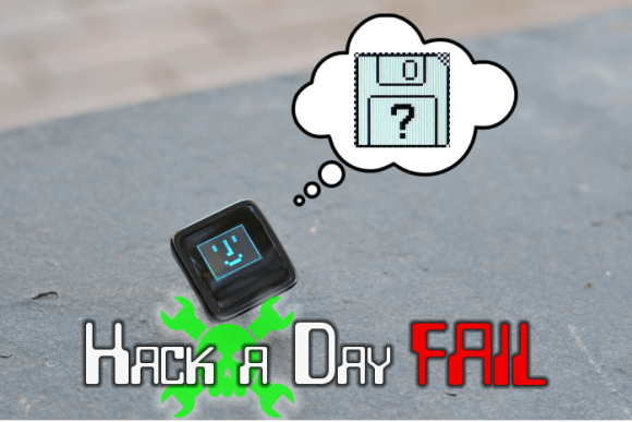
Everyone has a bad day right? Monday was a particularly bad day for the folks at Sparkfun. Customer support tickets started piling up, leading to the discovery that they had shipped out as many as 1,934 MicroViews without bootloaders.

MicroView is the tiny OLED enabled, Arduino based, microcontroller system which had a wildly successful Kickstarter campaign earlier this year. [Marcus Schappi], the project creator, partnered up with SparkFun to get the MicroViews manufactured and shipped out to backers. This wasn’t a decision made on a whim, Sparkfun had proven themselves by fulfilling over 11,000 Makey Makey boards to backers of that campaign.

Rather than downplay the issue, Sparkfun CEO [Nathan Seidle] has taken to the company blog to explain what happened, how it happened, and what they’re going to do to make it right for their customers. This positions them as the subject of our Fail of the Week column where we commiserate instead of criticize.

First things first, anyone who receives an effected MicroView is getting a second working unit shipped out by the beginning of November. Furthermore, the bootloaderless units can be brought to life relatively easily. [Nate] provided a hex file with the correct bootloader. Anyone with an Atmel AVR In-System Programming (ISP) programmer and a steady hand can bring their MicroView to life. Several users have already done just that. The bootloader only has to be flashed via ISP once. After that, the MicroView will communicate via USB to a host PC. Sparkfun will publish a full tutorial in a few weeks.

Click past the break to read the rest of the story.

So what went wrong? The crux of the problem is a common one to manufacturing: An incomplete production test. For many of their products, Sparkfun loads a single hex file containing the production test and the optiboot bootloader. The test code proves out the functionality of the device, and the bootloader allows the customer to flash the device with their own sketches. The problem is the bootloader normally connects to a PC host via USB. Enumerating a USB connection can take up to 30 seconds. That’s way too slow for volume production.

Sparkfun opted to skip the bootloader test, since all the pins used to load firmware were electrically tested by their production test code. This has all worked fine for years – until now. The production team made a change to the test code on July 18th. The new hex file was released without the bootloader. The production test ran fine, and since no one was testing the bootloader, the problem wasn’t caught until it was out in the wild.

The Sparkfun crew are taking several steps to make sure this never happens again.They’re using a second ATmega chip on their test fixture to verify the bootloader without the slow PC enumeration step. Sparkfun will also avoid changing firmware during a production run. If firmware has to change, they’re planning to beta test before going live on the production line. Finally, Sparkfun is changing the way they approach large scale production. In [Nathan's] own words:

Moving from low volume to mid-volume production requires a very different approach. SparkFun has made this type of mistake before (faulty firmware on a device) but it was on a smaller scale and we were agile enough to fix the problem before it became too large. As we started producing very large production runs we did not realize quality control and testing would need very different thinking. This was a painful lesson to learn but these checks and balances are needed. If it didn’t happen on Microview it would have happened on a larger production run someday in the future.

Everyone has bad days, this isn’t the first time Sparkfun has lost money due to a mistake. However, they’re doing the right thing by attacking it head on and fixing not only the immediate issue but the underlying thought process which allowed the problem to arise.


Filed under: Hackaday Columns, news