How to Fix Your Broken MicroView
 The response by GeekAmmo and Sparkfun to the MicroView problem has been amazing, but you can fix your broken one fairly simply if you're prepared to crack the case.

 The response by GeekAmmo and Sparkfun to the MicroView problem has been amazing, but you can fix your broken one fairly simply if you're prepared to crack the case.
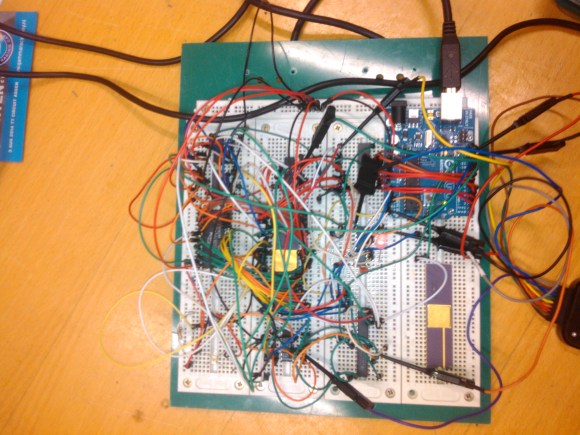
[Peter Bjornx] brings classic microprocessors and modern microcontrollers together with his Arduino bootstrapped 68008 computer. The Motorola 68008 is the 8-bit external bus version of the well-known 68000 (or 68k) microprocessor. A friend gave [Peter] one of these chips, so he built a simple computer around it.
This isn’t one of those clean retrocomputers with every connection carefully planned out and wire wrapped. [Peter's] created a true hack – a working 68k system on a breadboard created with whatever he had on hand at the time. The real gem of this system is the ROM. [Peter] replaced an EPROM chip with an Arduino.
In the not-so-good-old-days, microprocessors (and many microcontrollers) ran from an external ROM chip. This often was a UV-erasable EPROM. Carefully compiled code was burned into the EPROM with a device programmer. If the code wasn’t perfect, the EPROM had to be pulled and placed under a UV lamp for 20 minutes or so to erase it before it was time to try again. EPROM emulators were available, but they were way too expensive for the hobbyist.
Thankfully those days are far behind us now with the advent of EEPROM and then Flash. [Peter] didn’t want to revisit the past either, so he wrote a simple Arduino sketch which allowed it to act as an EPROM emulator, including address logging via the serial port.
The design still caused [Peter] some headaches, though. His major problem was a classic 68k issue, /DTACK timing. /DTACK or Data Transfer Acknowledge is one of several bus control signals used by the 68k. When the 68k performs a read from the data bus, it waits for /DTACK before it transfers data. The Arduino was too slow to release /DTACK in this case, which caused the 68k to think every read was immediately completed. There is a much clearer explanation of the 68k bus cycles on this Big Mess O Wires page. [Peter's] solution was simple – a D flip-flop connected to the address strobe took care of the timing issues.
It took quite a bit of tinkering, but the system eventually worked. Peter was able to run the 68008 from its reset vector into a simple loop using the Arduino. It’s only fitting that the 68k program loaded by the Arduino was an LED blinker, everyone’s favorite hardware Hello World.
Thanks [Robert!]


 The Fractal Lamp was designed using an IKEA dioder lamp with customized 3D printed and laser-cut parts.
A customized control box adjusts the desired color of lamp, giving it a unique look.
The Fractal Lamp was designed using an IKEA dioder lamp with customized 3D printed and laser-cut parts.
A customized control box adjusts the desired color of lamp, giving it a unique look.

 Eduardo Zola’s New Pong v2.0 offers up retro gaming goodness using a pair of 8 X 8 LED matrix boards.
A MAX7219 and Arduino MEGA 2560 microcontroller provide the muscle to get the game off and running.
Eduardo Zola’s New Pong v2.0 offers up retro gaming goodness using a pair of 8 X 8 LED matrix boards.
A MAX7219 and Arduino MEGA 2560 microcontroller provide the muscle to get the game off and running.

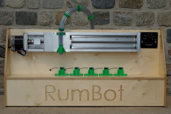
After five weekends of work, [Alex] completed his automatic drink maker, the RumBot. What makes this automated bartender different from others is the fact that it is fast. VERY fast. It can serve drinks to five different locations in as little as 3 seconds per drink. By [Alex]‘s estimation, this could keep a party of 100 people going without anyone waiting on a drink.
The RumBot can make either of five pre-programmed drinks at varying levels of alcoholic intensity, ranging from 1 (“Virgin”) to 10. And for that extra push over the cliff, you can turn the knob to 11 (“Problem”).
Drink selection itself is handled by a simple digital I/O on an Arduino with a 1950s-styled user interface. The frame is built out of wood and uses 3D Printed plastic parts. It houses a very robust servo on a belt stage to move the drink nozzle, and special sensors placed at either of the five drink locations detect a cup ready to be filled. Any cup placed at any of the positions will automatically be filled based on the RumBot’s settings at any particular time.
Based on the quality of the build and the increased speed of this automatic drink maker, this should be a huge hit at any party. With all the knobs turned to 11 though, it might be a good idea to have a breathalyzer on hand! All of the code and schematics for the project are available at the project site as well.


![]()
We are excited to announce that OpenTracker v2 by Tigal is our new partner in the Arduino At Heart Program and ready to be backed in an Indiegogo campaign.
OpenTracker is a fully open source commercial grade GPS/GLONASS vehicle tracker that comes with a free web interface for tracking it on Googlemaps or OpenStreetMaps.
The interface allows the tracking of a single vehicle or larger fleets simultaneously: currently it is possible to track the location, speed, altitude, heading, and address of the vehicle as well as save logs of location data for later use. With additional sensors it is also possible to track humidity, temperature and other parameters when desired.
The OpenTracker v2 is the second version of the original OpenTracker with many improved features, and a significant reduction in price.
Let’s have a look at some tech specs. The OpenTracker v2 is ready to run out-of-the-box and includes the same powerful 32-bit ATMEL SAM3A8C ARM controller as the Arduino Due, a Quectel M95 GSM/GPRS modem for wireless connectivity, a Quectel L76 GPS/GLONASS module with Assisted GPS, CAN-BUS, plenty of I/O options and a wide operating temperature range of -35°C to +80°C. The included CAN-BUS, plentiful I/O and on-board GSM/GPRS modem can be used to create many interesting applications such as CAN-BUS logger, SMS Gateway, SMS Remote Controller, and Weather Station with SMS notifications to name a few.
The OpenTracker v2 is available as a complete bundle including the Board, High-Quality Aluminum Enclosure, Power and Programming Cable as well as a GSM/GPS Antenna, or as a stand-alone board for those interested in using the board as an enhanced Arduino Due. The free online tracking interface is available at opentracker.tigal.com.
Support them on Indiegogo! (only a couple of days left but it’s flexible funding and going ahead with the manufacturing in any case!)
This page is next level of Virtual Touch Screen project.
First things is a distance, for virtual touch screen its less than 3 m, because the reflective area is too small. For radar (or sonar) its different, and the bigger size of object the stronger echo. Approximated range of detection the object as big as a wall, 30 meters.
Technically, there are two hardware parts were added, to fully demonstrate extra ordinary sensitivity of the VTS project. First one is the BlueTooth module. And second is a tablet, running android. Device that I have, doesn’t support USB host mode (OTG), otherwise I may be fine w/o BT, just transfer a data over USB cable, as it was done in two previous demo video clips. Have to say, it was not easy to represent 3D perspective on a flat screen, and picture below shows what I designed to complete a task:

Don’t think it requires a comments, the tricky part was to create an elliptical grid to show a distance. The number of circles is not limited to 2, I’d think about how to film next demo video, that ‘d show a “volume”.
Enjoy the movie:
There are two apples, and arduino measure position in 3D space both of them. X, Y, and Z coordinates plus P – power of reflected ultrasonic wave used to draw circles, with different colors. You can see movement of the red circle on screen when first apples moves.
edited on 21-08-2014
After thinking awhile how to show a “volume” on a flat tablet screen, I decide to remove filtering stage in a software, when a bunch of consecutive “layers” were shown as one single ring (object) on a screen. Now each packet of data received from single “spherical” layer creates a circle. As always packet includes X, Y, Z, and P. To make an image “clear” there are two others filters left over in the processing algorithm. One is rejecting data below ( selectable in a menu ) power threshold, and another rejects anything thats located farther specific (again, selectable) distance. This is why in a video you can see only a ball, but not me – operator making a movie.
Here is how the ball looks like on radar screen:

And video:
That;s it for now.


This page is next level of Virtual Touch Screen project.
Do you have this impression, like video I posted earlier was outdated? Software to draw a handwriting, mouse interface, etc. Wouldn’t it be nice to use a new era technology? And here it is.
Technically, there are two hardware parts were added, to fully demonstrate extra ordinary sensitivity of the VTS project. First one is the BlueTooth module. And second is a tablet, running android. Device that I have, doesn’t support USB host mode (OTG), otherwise I may be fine w/o BT, just transfer a data over USB cable, as it was done in two previous demo video clips. Have to say, it was not easy to represent 3D perspective on a flat screen, and picture below shows what I designed to complete a task:
Don’t think it requires a comments, the tricky part was to create an elliptical grid to show a distance. The number of circles is not limited to 2, I’d think about how to film next demo video, that ‘d show a “volume”.
Enjoy the movie:

 If you're having problems with your MicroView, you aren't alone, as it appears that close to 2,000 boards may have been sent out without bootloaders. We talk to Marcus Schappi about the problem.
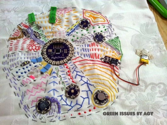
Agy Lee is an active member of the Singapore maker community and shared with us on the Arduino G+ Plus Community the interactive pad she prototyped using Lilypad Arduino:
She was inspired by the Sensor Demo Mat made by Kenneth Larsen some months before and that you can make yourself following this Instructables!