Posts with «arduino» label

H2gO Keeps Us from Drying Out

The scientific community cannot always agree on how much water a person needs in a day, and since we are not Fremen, we should give it more thought than we do. For many people, remembering to take a sip now and then is all we need and the H2gO is built to remind [Angeliki Beyko] when to reach for the water bottle. A kitchen timer would probably get the job done, but we can assure you, that is not how we do things around here.

A cast silicone droplet lights up to show how much water you have drunk and pressing the center of the device means you have taken a drink. Under the hood, you find a twelve-node NeoPixel ring, a twelve millimeter momentary switch, and an Arduino Pro Mini holding it all together. A GitHub repo is linked in the article where you can find Arduino code, the droplet model, and links to all the parts. I do not think we will need a device to remind us when to use the bathroom after all this water.

Another intrepid hacker seeks to measure a person’s intake while another measures output.

Save Some Steps with this Arduino Rapid Design Board

We’re all familiar with the wide variety of Arduino development boards available these days, and we see project after project wired up on a Nano or an Uno. Not that there’s anything wrong with that, of course, but there comes a point where some hobbyists want to move beyond plugging wires into header sockets and build the microcontroller right into their project. That’s when one generally learns that development boards do a lot more than break the microcontroller lines out to headers, and that rolling your own design means including all that supporting circuitry.

To make that transition easier, [Sean Hodgins] has come up with a simple Arduino-compatible module that can be soldered right to a PCB. Dubbed the “HCC Mod” for the plated half-circle castellations that allows for easy soldering, the module is based on the Atmel SAMD21 microcontroller. With 16 GPIO lines, six ADCs, an onboard 3.3 V regulator, and a reset button, the module has everything needed to get started — just design a PCB with the right pad layout, solder it on, and surround it with your circuitry. Programming is done in the familiar Arduino IDE so you can get up and running quickly. [Sean] has a Kickstarter going for the modules, but he’s also releasing it as open source so you’re free to solder up your own like he does in the video below.

It’s certainly not the first dev module that can be directly soldered to a PCB, but we like the design and can see how it would simplify designs. [Sean] as shown us a lot of builds before, like this army of neural net robots, so he’ll no doubt put these modules to good use.

Why Have Only One Radio, When You Can Have Two?

There are a multitude of radio shields for the Arduino and similar platforms, but they so often only support one protocol, manufacturer, or frequency band. [Jan Gromeš] was vexed by this in a project he saw, so decided to create a shield capable of supporting multiple different types. And because more is so often better, he also gave it space for not one, but two different radio modules. He calls the resulting Swiss Army Knife of Arduino radio shields the Kite, and he’s shared everything needed for one on a hackaday.io page and a GitHub repository.

Supported so far are ESP8266 modules, HC-05 Bluetooth modules, RFM69 FSK/OOK modules, SX127x series LoRa modules including SX1272, SX1276 and SX1278, XBee modules (S2B), and he claims that more are in development. Since some of those operate in very similar frequency bands it would be interesting to note whether any adverse effects come from their use in close proximity. We suspect there won’t be because the protocols involved are designed to be resilient, but there is nothing like a real-world example to prove it.

This project is unique, so we’re struggling to find previous Hackaday features of analogous ones. We have however looked at an overview of choosing the right wireless tech.

Hack a Day 28 Jul 09:00

Animatronic Puppet Takes Cues From Animation Software

Lip syncing for computer animated characters has long been simplified. You draw a set of lip shapes for vowels and other sounds your character makes and let the computer interpolate how to go from one shape to the next. But with physical, real world puppets, all those movements have to be done manually, frame-by-frame. Or do they?

Billy Whiskers: animatronic puppet

Stop motion animator and maker/hacker [James Wilkinson] is working on a project involving a real-world furry cat character called Billy Whiskers and decided that Billy’s lips would be moved one frame at a time using servo motors under computer control while [James] moves the rest of the body manually.

He toyed around with a number of approaches for making the lip mechanism before coming up with one that worked the way he wanted. The lips are shaped using guitar wire soldered to other wires going to servos further back in the head. Altogether there are four servos for the lips and one more for the jaw. There isn’t much sideways movement but it does enough and lets the brain fill in the rest.

On the software side, he borrows heavily from the tools used for lip syncing computer-drawn characters. He created virtual versions of the five servo motors in Adobe Animate and manipulates them to define the different lip shapes. Animate then does the interpolation between the different shapes, producing the servo positions needed for each frame. He uses an AS3 script to send those positions off to an Arduino. An Arduino sketch then uses the Firmata library to receive the positions and move the servos. The result is entirely convincing as you can see in the trailer below. We’ve also included a video which summarizes the iterations he went through to get to the finished Billy Whiskers or just check out his detailed website.

[Jame’s] work shows that there many ways to do stop motion animation, perhaps a part of what makes it so much fun. One of those ways is to 3D print a separate object for each character shape. Another is to make paper cutouts and move them around, which is what [Terry Gilliam] did for the Monty Python movies. And then there’s what many of us did when we first got our hands on a camera, move random objects around on our parent’s kitchen table and shoot them one frame at a time.

Single-handed smartwatch text entry with WrisText

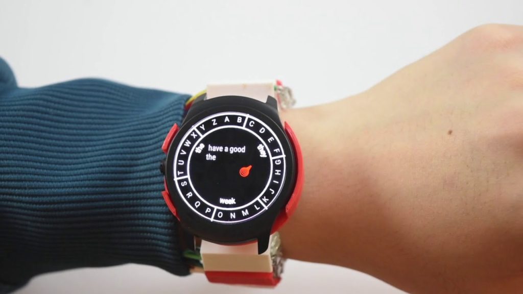
Smartwatches can keep us informed of incoming information at a glance, but responding still takes the use of another hand, potentially occupied by other tasks. Researchers at Dartmouth College are trying to change that with their new WrisText system.

The device divides the outside of a Ticwatch 2 into six sections of letters, selected by the movement of one’s wrist. As letters are chosen, possible words are displayed on the screen, which are then selected automatically, or by rubbing and tapping gestures between one’s finger and thumb. 

The prototype employs an Arduino DUE to pass information to a computer, along with proximity and piezo sensors to detect hand and finger movements. 

We present WrisText – a one-handed text entry technique for smartwatches using the joystick-like motion of the wrist. A user enters text by whirling the wrist of the watch hand, towards six directions which each represent a key in a circular keyboard, and where the letters are distributed in an alphabetical order. The design of WrisText was an iterative process, where we first conducted a study to investigate optimal key size, and found that keys needed to be 55o or wider to achieve over 90% striking accuracy. We then computed an optimal keyboard layout, considering a joint optimization problem of striking accuracy, striking comfort, word disambiguation. We evaluated the performance of WrisText through a five-day study with 10 participants in two text entry scenarios: hand-up and hand- down. On average, participants achieved a text entry speed of 9.9 WPM across all sessions, and were able to type as fast as 15.2 WPM by the end of the last day.

More information can be found in the project’s research paper, or you can see it demonstrated in the video below.

DolphinView headset lets you see the world like Flipper!

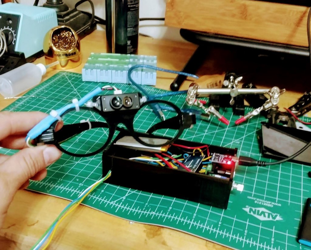
Dolphins are not only amazing swimmers and extremely intelligent, but can also observe their surroundings using echolocation. While extremely useful in murky water, Andrew Thaler decided to make a device that would enable him to him observe his (normally dry) surroundings with a similar distance-indicating audio setup.

While he first considered using an ultrasonic sensor, he eventually settled on LiDAR for its increased range, and uses an Arduino to translate distance into a series of audio clicks. Sound is transferred to Thaler through bone conduction speakers, mimicking the way dolphins hear without external ears. 

He notes that while using the “DolphinView” headset is initially disorienting, he was eventually able correlate his surroundings with the system’s audio feedback. Arduino code and parts list is available on GitHub, and the mechanical frame design can be found on Thingiverse if you’d like to build your own!

Arduino Blog 26 Jul 15:31

Two CD-ROM drives combined into fledging drawbot

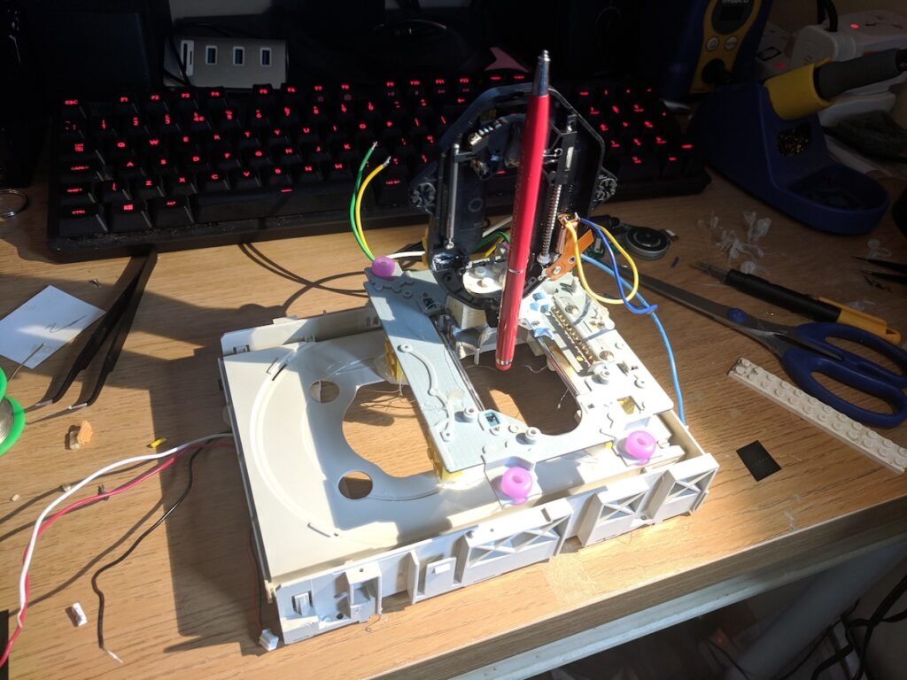
Even if you don’t have access to fancy tools like a 3D printer or CNC router, that doesn’t mean you can’t make something interesting. James, using only a “hot glue gun, some scissors, and a screwdriver,” was able to construct a rudimentary drawing robot that marks paper with a sharpie.

2 CD drives were creatively modified to form X, Y, and Z axes, letting him lower his writing instrument and draw. An Arduino Uno along with an Adafruit Motor Shield forms the controls for the device, and the structure is built out of LEGO bricks. 

As of now it’s described as more of an “Etch A Sketch type thing,” but it looks like a great starting point for more advanced drawbots in the future! Code for the build is available on GitHub.

Ping pong ball bounces forever under Arduino control

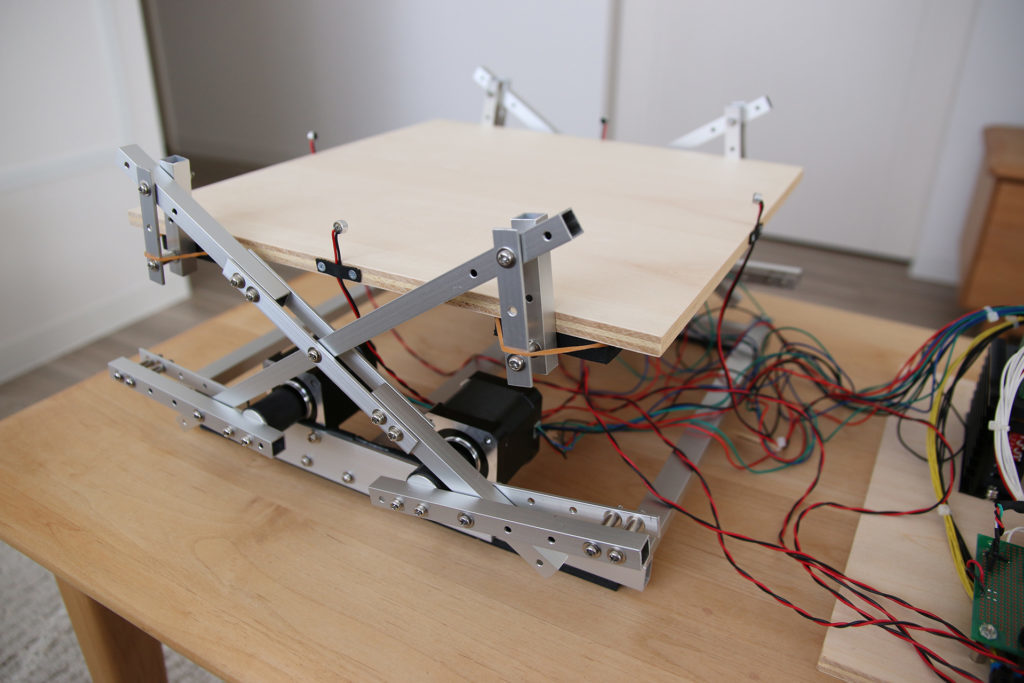
As spotted on Reddit, maker “tkuhn” of Electron Dust decided to make a machine “with the sole goal of keeping a ping pong ball bouncing for as long as possible.” 

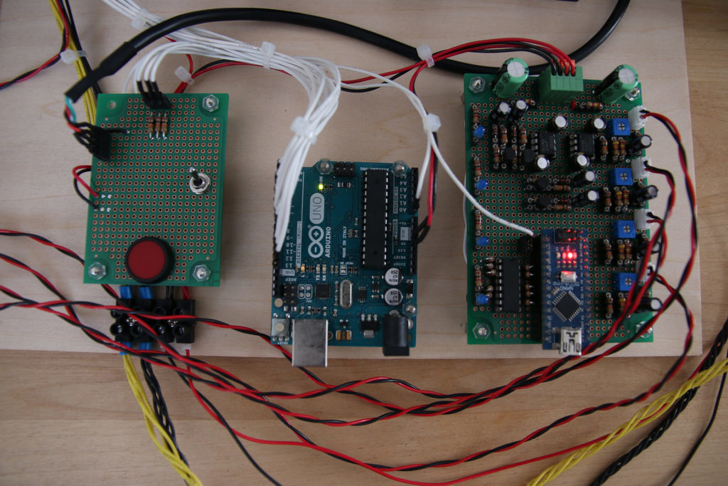
To accomplish this, he turned to audio feedback using the time difference between when four electret microphones sense the sound of the bouncing ball. Audio processing is accomplished with the help of a simple flip-flop circuit, while an Arduino Nano is used to reset it after each cycle.

Data is then passed along to an Arduino Uno, which employs four steppers motors/drivers and a linkage system to keep the ball in play. This impressive setup can be seen in the video below, and code is available on GitHub.

Arduino Blog 25 Jul 16:11
arduino  featured  nano  uno  

Add fading light effects to the buttons on your arcade controller

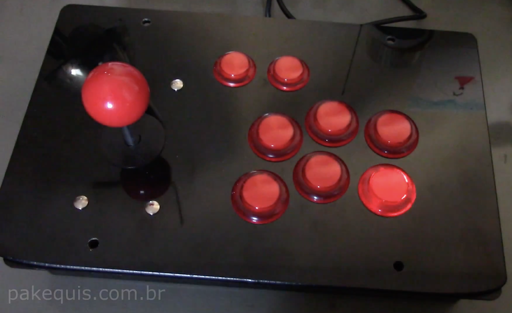
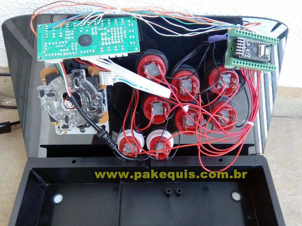
Making a custom arcade cabinet has become something of a rite of passage for aspiring hackers. As seen here, maker Rodrigo decided to add an extra bit of “flair” to his build (Portuguese), with buttons that light up under Arduino power. 

As demonstrated in the video below, the button lights slowly fade out after being pressed, and he’s created a pair of these light-up control boxes, one featuring blue buttons and the other red.

Notably, he’s using a separate controller to pass signals to his setup, leaving each Arduino free to control the lighting. Code for the project can be found on GitHub if you’d like to try something similar yourself.

Arduino-Controlled Signal Attenuation

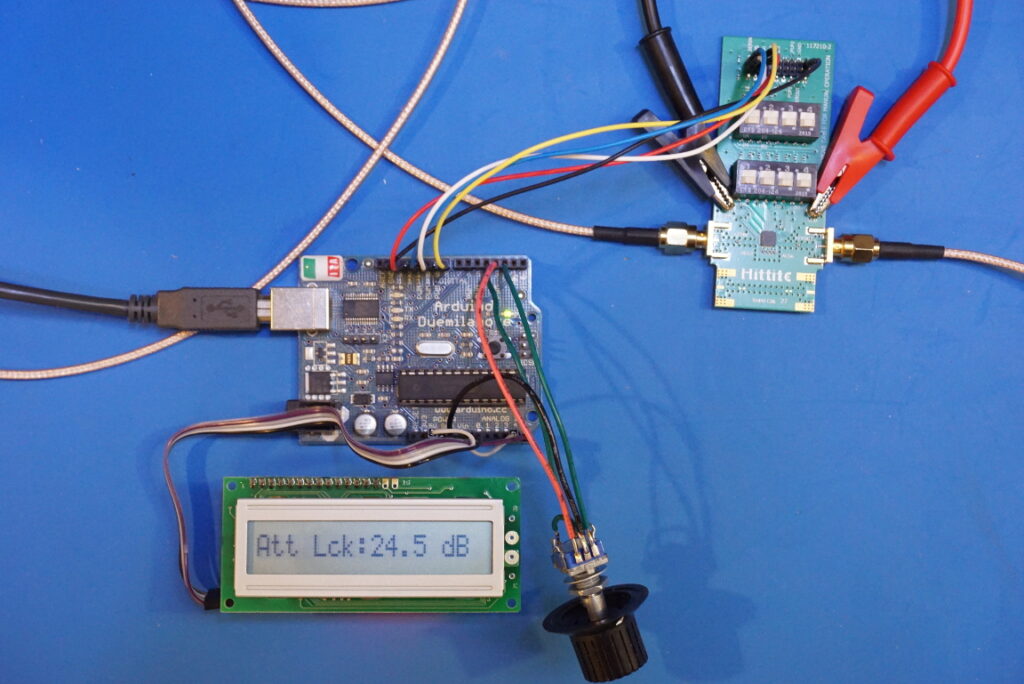
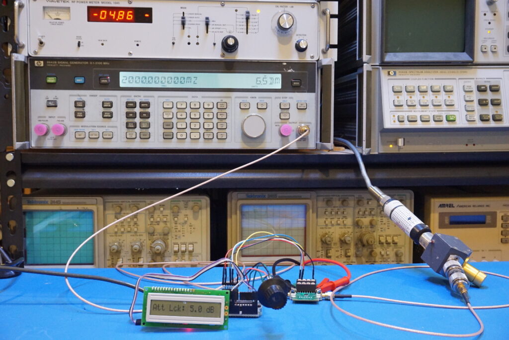
There are many ways to modify analog and digital electrical signals, but things get a bit more complicated—or at least specialized—when working with coaxial signal transmission. To this end, Kerry D. Wong found an unused attenuator evaluation board in his “miscellaneous PCB bin,” and decided to give it a new life using an Arduino.

The attenuator functions through a set of switches to set power dissipation from 0 to 31.5 dB, but it can use a serial interface for this function as well. In his new setup, the Arduino provides the needed control signal, via a user interface consisting of an encoder and LCD display.

The fact that it’s now programmable would also open up automated testing possibilities. More on this project is seen in the video below, with the Arduino configuration showing up at around 10:00.