Hackaday brought you a first look the Arduino MKR Vidor 4000 when it announced. Arduino sent over one of the first boards so now we finally have our hands on one! It’s early and the documentation is still a bit sparse, but we did get it up and running to take the board through some hello world exercises. This article will go over what we’ve been able to figure out about the FPGA system so far to help get you up and running with the new hardware.
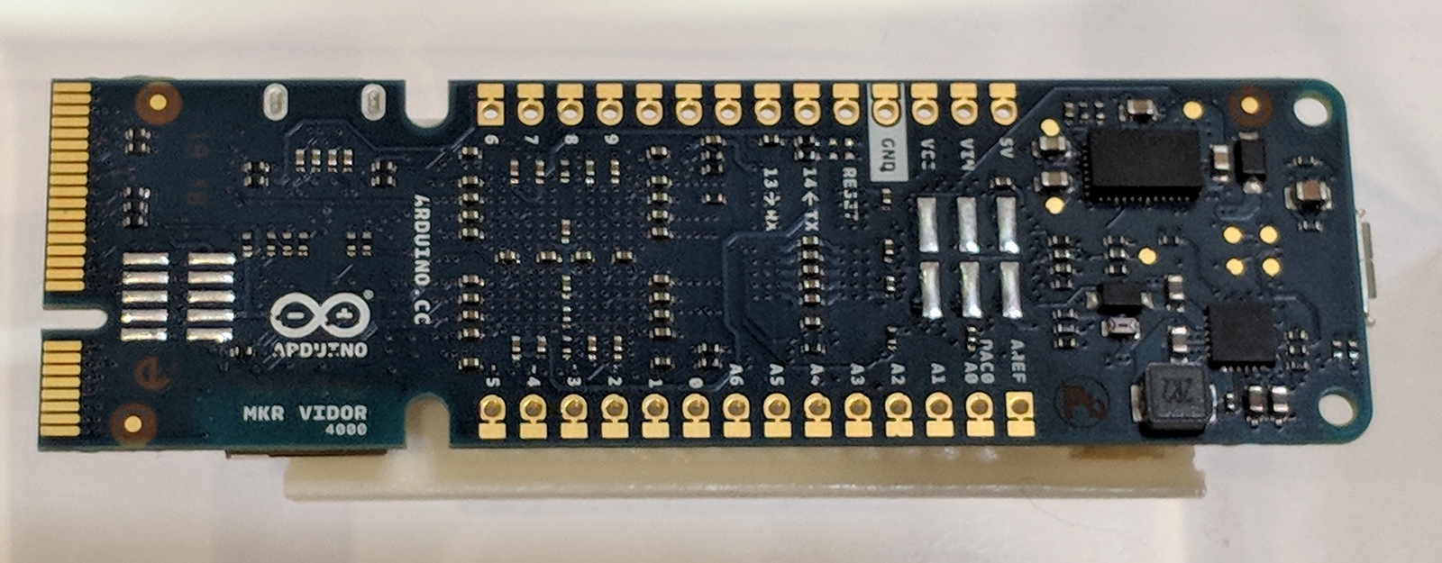
Just to refresh your memory, here’s what is on the Vidor board:
- 8 MB SRAM
- A 2 MB QSPI Flash chip — 1 MB allocated for user applications
- A Micro HDMI connector
- An MIPI camera connector
- Wi-Fi and BLE powered by a U-BLOX NINA W10 Series device
- MKR interface on which all pins are driven both by SAMD21 (32-bit ARM CPU) and FPGA
- Mini PCI Express connector with up to 25 user programmable pins
- The FPGA (an Intel/Altera Cyclone 10CL016) contains 16K Logic Elements, 504 KB of embedded RAM, and 56 18×18 bit HW multipliers
Sounds good. You can get more gory technical details over at Arduino and there’s even a schematic (.zip).
Documentation
Documentation is — so far — very hard to come by but the team is working to change that by the day. Here are the resources we’ve used so far (in addition to the schematic):
In addition, Arduino just released an example FPGA project for Quartus. I’ll explain what that means in a bit.
Get Up and Running with the Arduino Desktop IDE
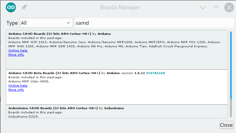
Despite the getting started guide, it doesn’t appear the libraries are usable from the cloud-based IDE, so we followed the instructions to load the beta board support for the MKR 4000 into our desktop IDE. Be aware that the instructions show the “normal” SAMD board package, but you actually want the beta which says it is for the MKR 4000. If you search for SAMD in the Boards Manager dialog, you’ll find it (see the second entry in the image below).
The libraries we grabbed as ZIP files from GitHub and used the install library from ZIP file option with no problems.
What’s the Code Look Like?
The most interesting part of this board is of course the inclusion of the FPGA which left us wondering what the code for the device would look like. Browsing the code, we were a bit dismayed at the lack of comments in all but the JTAG code. We decided to focus first on the VidorPeripherals repository and dug into the header file for some clues on how everything works.
Looking at VidorPeripherals.h, you can see that there’s a few interesting I/O devices include SPI, I2C, UART, reading a quadrature encoder, and NeoPixel. There’s also a few headers that don’t exist (and presumably won’t get the define to turn them on) so don’t get too excited by some of the header file names until you make sure they are really there.
Then we decided to try the example test code. The library provides a global FPGA object that you need to set up:
// Let's start by initializing the FPGA
if (!FPGA.begin()) {
    Serial.println("Initialization failed!");
    while (1) {}
}

// Let's discover which version we are running
int version = FPGA.version();
Serial.print("Vidor bitstream version: ");
Serial.println(version, HEX);

// Let's also ask which IPs are included in this bitstream
FPGA.printConfig();
The output of this bit of code looks like this:
Vidor bitstream version: 1020107
number of devices 9
1 01000000 MB_DEV_SF
1 02000000 MB_DEV_GPIO
4 04000000 MB_DEV_I2C
6 05000000 MB_DEV_SPI
8 06000000 MB_DEV_UART
1 08000000 MB_DEV_SDRAM
4 09000000 MB_DEV_NP
11 0A000000 MB_DEV_ENC
0 0B000000 MB_DEV_REG
In many cases, the devices provided by the FPGA are pretty transparent. For example, here’s another snip from the example code:
// Ok, so we know now that the FPGA contains the extended GPIO IP
// The GPIO pins controlled by the FPGA start from 100
// Please refer to the online documentation for the actual pin assignment
// Let's configure pin A0 to be an output, controlled by the FPGA
FPGA.pinMode(33, OUTPUT);
FPGA.digitalWrite(33, HIGH);

// The same pin can be read by the SAMD processor :)
pinMode(A0, INPUT);
Serial.print("Pin A0 is ");
Serial.println(digitalRead(A0) == LOW ? "LOW" : "HIGH");

FPGA.digitalWrite(33, LOW);
Serial.print("Pin A0 is ");
Serial.println(digitalRead(A0) == LOW ? "LOW" : "HIGH");
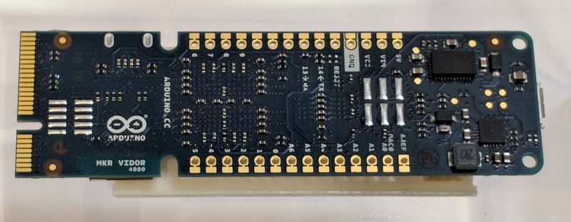
That’s easy enough and it is nice that the pins are usable from the CPU and FPGA. We couldn’t find the documentation mapping the pins, but we assume it is coming.
Using, say, an extra serial interface is easy, too:
SerialFPGA1.begin(115200);
while (!SerialFPGA1);
SerialFPGA1.println("test");
Bitstream
So where’s the FPGA code? As far as you can tell, this is just a new Arduino with a lot of extra devices that connect through this mysterious FPGA object. The trick is that the FPGA code is in the library. To see how it works, let’s talk a little about how an FPGA operates.
When you write a program in C, that’s not really what the computer looks at, right? The compiler converts it into a bunch of numbers that tell the CPU to do things. An FPGA is both the same and different from that. You write your program — usually in a hardware design language like Verilog or VHDL. You compile it to numbers, but those numbers don’t get executed like a CPU does.
The best analogy I’ve been able to think of is that an FPGA is like one of those old Radio Shack 100-in-1 electronic kits. There are a bunch of parts on a board and some way to connect them with wires. Put the wires one way and you have a radio. Put them another way and you have a burglar alarm. Rewire it again and you have a metal detector. The numbers correspond to wires. They make connections and configure options in the FPGA’s circuitry. Unless you’ve built a CPU, there’s nothing in there examining and acting on the numbers like there would be with a CPU.
The numbers that come out of an FPGA tool is usually called a bitstream. Someone has to send that bitstream to an FPGA like the Cyclone onboard the Arduino every time it powers up. That someone is usually a memory device on the board, although the CPU can do it, too.
So that leads to two questions: Where is the bitstream? How does it get to the FPGA?
The answer to the first question is easy. If you look on Github, you’ll see in the library there is a file called VidorBase.cpp. It has the following lines:
__attribute__ ((used, section(".fpga_bitstream")))
const unsigned char bitstream[] = {
    #include "app.ttf"
};
What this means if there is an array called bitstream that the linker will put it in a specially marked section of memory. That array gets initialized with app.ttf which is just an ASCII file full of numbers. Despite the name, it is not a TrueType font. What do the numbers mean? Hard to say, although, in theory, you could reverse engineer it just like you can disassemble binary code for a CPU. However, it is the configuration required to make all the library calls we just talked about work.
The second question about how it gets to the FPGA configuration is a bit of a mystery. As far as we can tell, the bootloader understands that data in that section should get copied over to the FPGA configuration memory and does the copying for you. It isn’t clear if there’s a copy in the main flash and a copy in the configuration flash but it seems to work transparently in any event.
There’s a checksum defined in the code but we changed it and everything still worked. Presumably, at some point, the IDE or the bootloader will complain if you have the wrong checksum, but that doesn’t appear to be the case now.
By the way, according to the Arduino forum, there are actually two bitstreams. One that loads on power-up that you would rarely (if ever) change. Then there is another that is the one included with the library. You can double-click the reset button to enter bootloader mode and we suspect that leaves the FPGA initialized with the first bitstream, but we don’t know that for sure. In bootloader mode, though, the red LED onboard has a breathing effect so you can tell the double click works.
What about my FPGA Code?
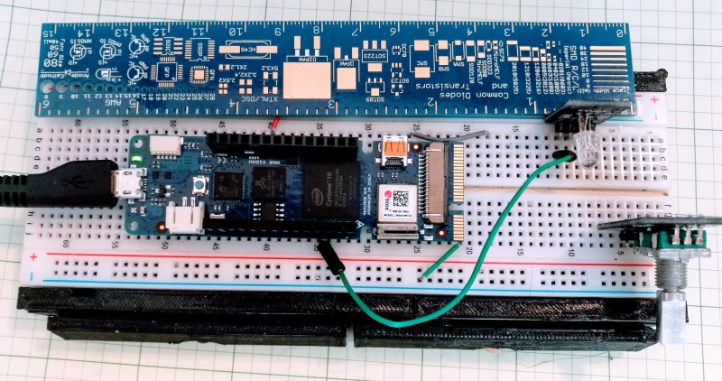 This isn’t great news if you were hoping for an easy Arduino-like way to do your own FPGA development in Verilog or VHDL. Intel will give you a copy of Quartus Prime which will generate bitstreams all day for you. We think — but we aren’t sure — that the ASCII format is just a raw conversion from binary of the bitstream files.
Very recently, Arduino provided a Quartus project that would create a bitstream. This provides a few key pieces of the puzzle, like the constraint file that lets the FPGA compiler find the different parts on the board.
However, even with that project, you still have some reverse engineering to do if you want to get started. Why? Here’s what Arduino says about loading your own FPGA code (we added the emphasis):
Quartus will produce a set of files under the output_files directory in the project folder. In order to incorporate the FPGA in the Arduino code you need to create a library and preprocess the ttf file generated by Quartus so that it contains the appropriate headers required by the software infrastructure. Details of this process will be disclosed as soon as the flow is stable.
Programming the FPGA is possible in various ways:
- Flashing the image along with Arduino code creating a library which incorporates the ttf file
- Programming the image in RAM through USB Blaster (this requires mounting the FPGA JTAG header). this can be done safely only when SAM D21 is in bootloader mode as in other conditions it may access JTAG and cause a contention
- Programming the image in RAM through the emulated USB Blaster via SAM D21 (this component is pending release)
In addition, the repository itself says that some key pieces are missing until they can work out licensing or clean up the code. So this gets us closer, but you’d still need to reverse engineer the header from the examples and/or figure out how to force the processor off the JTAG bus. The good news is it sounds like this information is coming, it just isn’t here yet.
Of course, you are going to need to understand a lot more to do anything significant. We know the FPGA is set in the AS configuration mode. We also asked Arduino about the clock architecture of the board and they told us:
[The CPU] has its own clock which is used to generate a 48 MHz reference clock that is fed to the FPGA (and that can be removed at any time to “freeze” fpga). In addition to this reference clock, [the] FPGA has an internal RC oscillator which can’t be used as [a] precise timing reference for tolerance issues but can be used in case you don’t want [the CPU] to produce the reference clock.
Of course, the FPGA has a number of PLLs onboard that can take any valid clock and produce other frequencies. For example, in the vision application, Arduino demonstrated, the 48 MHz clock is converted into 24 MHz, 60 MHz, 100 MHz, and 120 MHz clocks by PLLs.
Mix and Match?
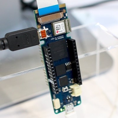 One thing that is disappointing is that — at least for now — you won’t be able to mix and match different FPGA libraries. There is exactly one bitstream and you can’t just jam them together. Although FPGAs can often be partially configured, that’s a difficult technique. But we were a little surprised that the IDE didn’t understand how to take libraries with, for example, EDIF design files for IP that would all get compiled together. That way I could pick the Arduino UART and mix it with the Hackaday PWM output module along with my own Verilog or VHDL.
The way things are structured now you will have one bitstream that is precompiled by another tool (probably Quartus for the foreseeable future). It will match up with a particular C++ library. And that’s it. Doesn’t matter how much of the FPGA is left over or how much of it you really use, you will use it all for the one library.
Of course, you can load another library but it is going to replace the first one. So you only get one set of functions at a time and someone else gets to decide what’s in that set. If you roll your own, you are going to have to roll your own all the way.
What’s Next?
It is still early for the Arduino Vidor. We are hopeful we’ll get the tools and procedures necessary to drop our own FPGA configurations in. It would be great, too, if the stock libraries were available in source format including the Verilog HDL. The recent GitHub release shows quite a bit, although it isn’t all of the examples, it is probably enough if we get the rest of the information.
As for a more intuitive interface, we don’t know if that’s in the cards or not. We don’t see much evidence of it, although posts on the Arduino forum indicate they will eventually supply an “IP Assembler” that will let you compose different modules into one bitstream. We don’t know if that will only work with “official” modules or not. However, we know the Arduino community is very resourceful so if we don’t get a good ecosystem it will not surprise us if someone else makes it happen. Eventually.
For now, we will continue to play with the existing bitstreams that become available. There are some neat new features on the CPU, too. For example, you can map two of the unused serial modules. There’s a hardware-based cooperative multitasking capability. As more details on the FPGA emerge, we’ll keep you posted and if you learn something, be sure to leave word in the comments so everyone can benefit.