Riding a bicycle can be a great way to get around, and/or even to get some needed exercise. When you mix in automobile or foot traffic, though, things get a bit more complicated. This could be blamed, in part, on the fact that bikes don’t have the same running lights, turn or brake signals as motorized vehicles.
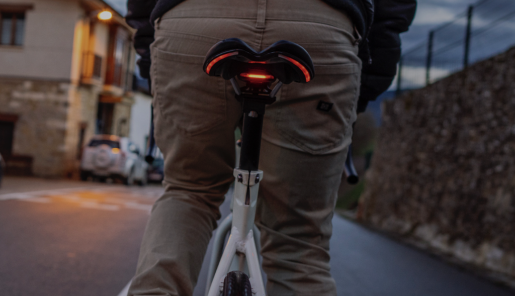
To address this problem, BLINK!’s patented Integrated Lighting System (iLS) has been designed to provide a visible communication solution that’s easily understandable by other road users.
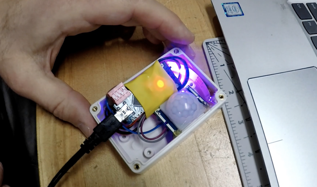
This custom saddle—which was prototyped using an ATmega328P-based Arduino— features lighting for 270º visibility, and brightens automatically for braking when deceleration is detected. In addition, iLS includes a pair of remotely activated turn signals. This allows the rider to indicate direction changes without removing his or her hand from the handlebars to awkwardly point.
BLINK! has been embedded into a wide range of saddles and installation should be fairly straightforward. Not only will it certainly help enhance road safety, iLS will look fantastic while doing so.
Nixie tubes require electricity in the range of 180VDC, making them challenging to work with. Maker Christine Thompson, however, decided to take Nixie art to a new level, creating a clock with three different types of tubes!
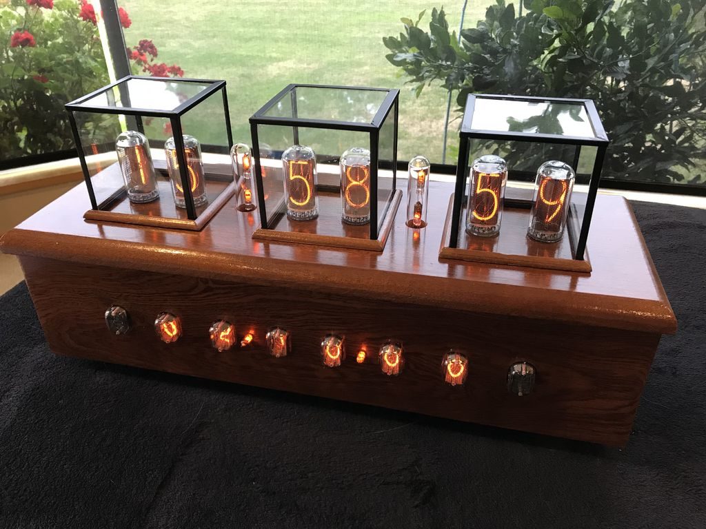
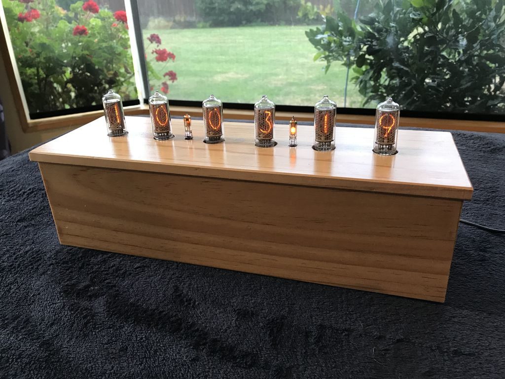
This clock, or perhaps more accurately “info display,” shows the time and date with six IN-18 tubes mounted on the top. In the front, six IN-12A and two IN-15A tubes are also available to show time, date, pressure, temperature, and humidity.
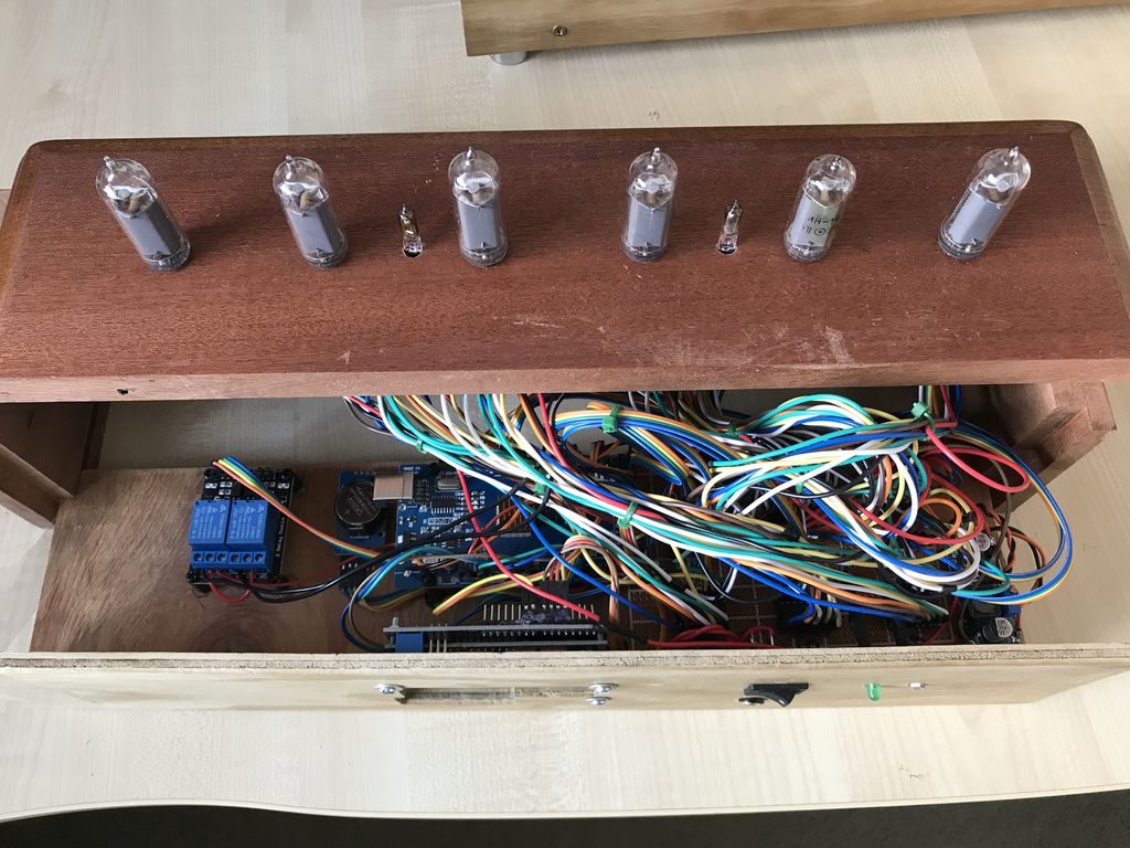
A pair of Arduino Mega boards are used to control this retro-inspired contraption, along with an array of wiring, perf board, and other components, stuffed inside a very nice wooden enclosure.
This is my first Nixie styled clock I have constructed. The clock actually consists of two clocks, the first being a 6 x IN-18 tube clock which is mounted on the clock’s top and displays both time and date. The second clock, this time based on 6 x IN-12A and 2 x IN-15A nixie tubes displays at the front of the clock and can display, time, date, pressure (with units and trend), temperature (both Centigrade and Fahrenheit) and, humidity (with units and trend). The time and date are separated with two single neon lamp-based separators, while only one of these lamps is displayed, to represent a decimal point, when the pressure, humidity or temperature is displayed. Both these clocks use “Direct/Static Drive” to power the displays and are based on two Arduino Mega 2560 boards. The fourteen tubes are driven by 12V to 170V DC to DC boost power supplies and 14 x K155 IC chips. The clock also powers two sets of Neon Lamps which switch off while the clock goes through its cathode cleaning cycle which happens at 19, 39 and 55 minutes past each hour. This cathode cleaning cycle consists of all six tubes displaying the digits 0 through 9 in sequence 6 times.
In addition the clock will sound a chime at 15, 30, 45 and 60 minutes. At the 60 minute chime the hour chime is also sounded. The chimes are standard MP3 files using a simple MP3 player controlled by the Arduino mega. In order to save on tube life all tubes are switched off automatically when the light level in the room dims to a predefined level, this is achieved using a LRD resistor located at the back of the clock. To help dissipate any heat build up both Arduino Mega ICs have copper heat fins attached and a 5V fan draws air out of the clock, cool air entering through a hole in the bottom plate.
The user can adjust the time, date, chimes, and chimes volume using one of two 16×2 LCD displays, located at the back of the clock. The BME280 temperature, humidity, and pressure sensor is mounted on the back of the clock so as to not be affected by the clock’s internal temperature.
A demo is seen in the video below, while more info and Arduino code can be found in the project’s write-up.
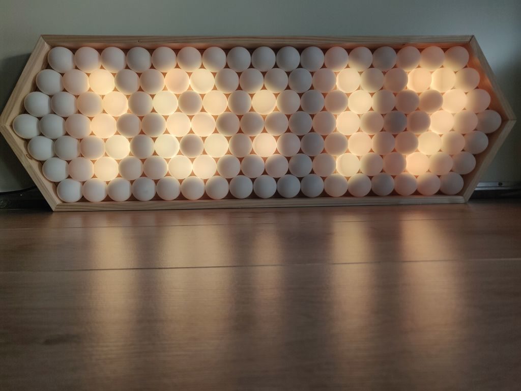
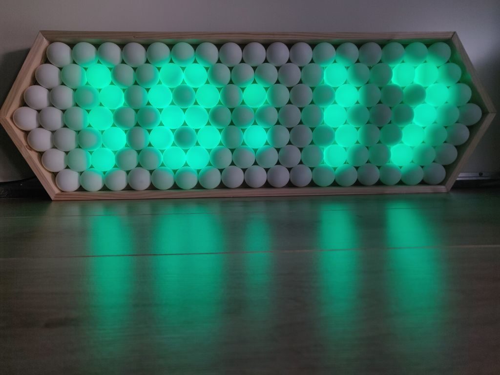
Ping pong balls have long been known as excellent LED diffusers, but few have taken this technique as far as Thomas Jensma. His colorful clock features 128 LEDs, arranged in an alternating pattern, and housed in a stretched-out hexagonal wood frame.
For control, the device uses an Arduino Nano, along with a RTC module for accurate timekeeping. Demos of the clock can be seen below, cycling through numbers and testing out the FastLED library.
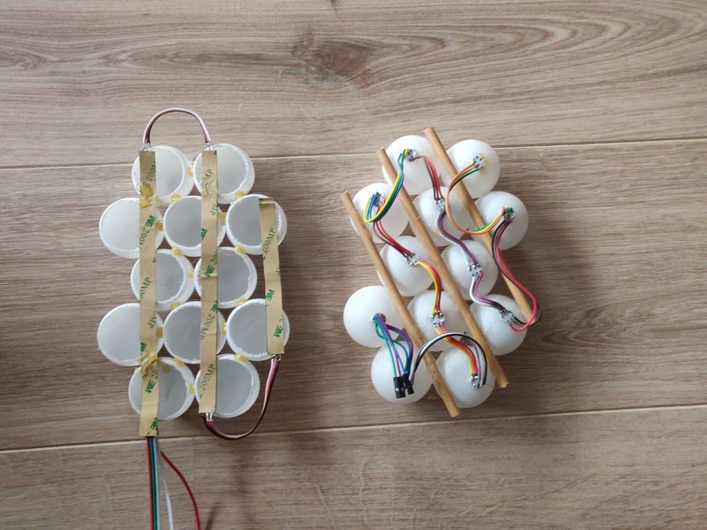
Code for the build is available in Jensma’s write-up. This also includes tips on using table tennis balls as diffusers, as well as how to create an orderly array out of these spheres—useful in a wide range of projects.
Potentially, one of the great things about having a device connected to the network is that you can update it remotely. However, how do you make that happen? If you use the Arduino setup for the ESP8266 or ESP32, you might try [scottchiefbaker’s] library which promises to make the process easy.
Adding it looks to be simple. You’ll need an include, of course. If you don’t mind using port 8080 and the path /webota, you only need to call handle_webota() from your main loop. If you want to change the defaults, you’ll need to add an extra call in your setup. You also need to set up a few global variables to specify your network parameters.
The only caveat is that long delay statements in your loop can block things from working and aren’t a great idea anyway. If you have them, you can replace all your delay calls with webota_delay which will stop the system from ignoring update requests.
The code started from a different online tutorial but packaged the code up nicely for reuse. To do an update, simply navigate to the device with a web browser and use the correct port number and path. From there you can upload a new binary image taken from the Arduino IDE with the export compiled binary command.
The only concern we saw was the code didn’t appear to authenticate you at all. That means anyone could load code into your ESP. That might be ok on a private network, but on the public Internet it is surely asking for trouble. The original tutorial code did have a hardcoded user and password, but it didn’t look very useful as the password was in the clear and didn’t stop you from uploading if you knew the right URL. Dropping it from the library probably makes sense, but we would want to build some kind of meaningful security into anything we deployed.
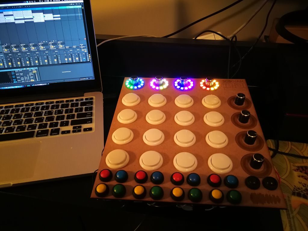
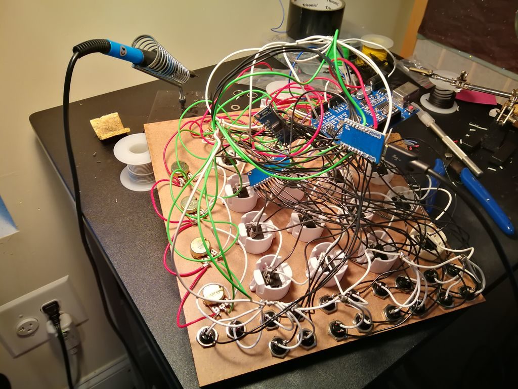
Michael Sobolak was inspired by the hardware dedicated to Ableton digital audio software, along with the DIY MIDI Fighter pads that others have constructed, to make his own light-up version.
His device is cut out of ¼-inch MDF, housing a 4×4 array of main buttons, 18 smaller buttons on the bottom and eight potentiometers, four of which are surrounded by NeoPixel rings.
To handle this massive array of inputs, he turned to the use of multiplexers, creating a spaghetti-like—though functional—wiring arrangement hidden underneath. The pad uses an Arduino Uno to control the NeoPixels, while a separate board is tasked with the MIDI interface.
You can see Sobolak’s project crank out music in the video below, with LEDs that react to potentiometer input settings.
Arduino boards are used in a wide—massive even—variety of projects. Sometimes, however, all you need is something to give your project the ability to blink an LED, sound an alarm, or accomplish some other simple task.
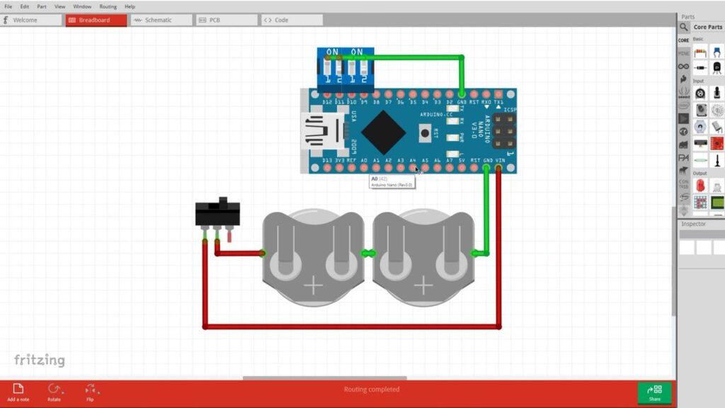
For this purpose, maker Jeremy S. Cook has developed a sort of standard method for using these devices, with a 4-position DIP switch soldered to inputs D9-D12, and a double-CR2032 battery pack attached with shrink wrap.
This standardization makes for a very compact setup that can be implemented in a project very quickly. The configuration also highlights the use of “INPUT_PULLUP” in Arduino code, with switches wired to ground. Cook’s technique avoids floating inputs without the need for external resistors.
The modern keyboard enthusiast is blessed with innumerable choices when it comes to typing hardware. There are keyboards designed specifically for gaming, fast typing, ergonomics, and all manner of other criteria. [iot4c] undertook their own build for no other reason than nostalgia – which sounds plenty fun to us.
An Arduino Leonardo is pressed into service for this hack. With its USB HID capabilities, it’s perfectly suited for custom keyboard builds. It’s built into a working Atari 65XE computer, and connected to the keyboard matrix. The Keypad and Keyboard libraries are pressed into service to turn keypresses on the 80s keyboard into easily digseted USB data.
There’s plenty of room inside the computer for the added hardware, with the USB cable neatly sneaked out the rear. [iot4c] notes that everything still works and the added hardware does not cause any problems, as long as it’s not used as a computer and a keyboard at the same time.
Students at the University of Illinois at Urbana-Champaign have a brain-computer interface that can measure brainwaves. What did they do with it? They gave it to Alma, a golden labrador, as you can see in the video below. The code and enough info to duplicate the electronics are on GitHub.
Of course, the dog doesn’t directly generate speech. Instead, the circuit watches her brainwaves via an Arduino and feeds the raw data to a Raspberry Pi. A machine learning algorithm determines Alma’s brainwave state and plays prerecorded audio expressing Alma’s thoughts.
Alma’s collar duplicates — to some degree — the fictional collar from the movie Up. Of course, Dug was a bit more loquacious. It isn’t very clear from the video how many states the program classifies. A quick peek at the code reveals five audio clips but only one appears to be wired to the recognizer — the one for a treat. We think it might be a harder problem to figure out when the dog does not want a treat.
The last time we saw a talking dog collar it was phone-controlled. If you really want to probe a brain — canine or human — you could do worse than to check out OpenHardwareExG.
Part of the joy of owning a dog is feeding it. How often do you get to make another living being that happy? However, sometimes you can’t be there when your best friend is hungry. [El Taller De TD] built an auto dog feeder using an Arduino and stepper motor. The video and links are in Spanish, but if your Spanish is rusty, YouTube’s caption autotranslation isn’t bad and Google Translate can help you with the web site.
The electronics are reasonably simple: an Arduino, a Bluetooth module, and a stepper motor driver. Mechanically, the motor and some PVC pipe are all you need. There’s a small phone application to drive the Bluetooth using App Inventor.
This would be a pretty straightforward first project and — of course — could be useful for any kind of animal. For dog use, we might have hardened the external wires and circuit boards a bit though. In addition there are plenty of things you could do in software, for example you could feed every 8 hours. It seems like you could add a sensor to tell when you are out of food, or perhaps if the food was not feeding for some reason.
We’ve looked at using App Inventor with Bluetooth before and it is pretty easy. We might have been tempted to go with Blynk to have more options for communication, but either way is pretty easy.
Rubik’s Cubes seem to have been most popular in the 1980s, but never really went away. As such, if you have one lying around your house unsolved, why not ‘simply’ construct a machine to do this for you?
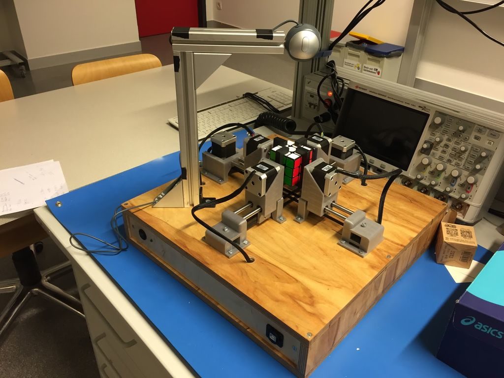
One possibility is the Q-Bot, outlined here. While it won’t break any world records, it’s a solid-looking assembly that appears to be relatively easy to build.
The Q-Bot features six NEMA 17 stepper motors, four of which turn one face at a time. When needed, the other two use timing belts to alternatively pull opposed stepper motor pairs back, allowing the other two to rotate the entire assembly. An Arduino Mega is utilized to control the steppers via a custom shield, with a computer running the Kociemba’s Algorithm.