If you’ve ever considered constructing your own wireless RC transmitter, be sure to check out this build by Electronoobs.
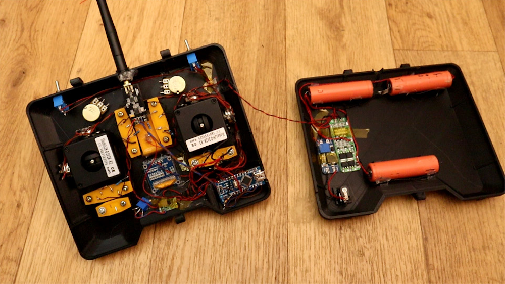
The device uses an nRF24L01+ module to transmit inputs from a pair of joysticks and toggle switches, along with an Arduino Nano for interface and control.
What sets this project apart from his previous versions, however, is the very nice 3D-printed enclosure for the electronics and a pair of high-quality joysticks that allow for precise input.
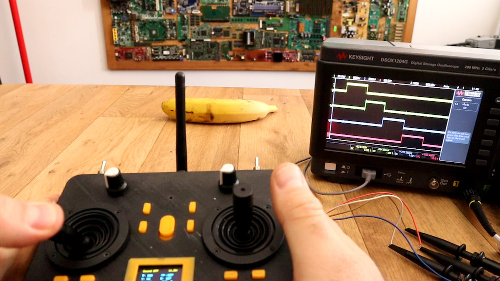
Additionally, Electronoobs’ latest design features tuning buttons to properly center the sticks, and an OLED display to show the actual input value that it’s sending to the receiver (a simple Nano/nRF24L01+ setup for demo purposes).
Yes, I’ve made another radio controller. Why? well, I wanted to have a more commercial look. So, I’ve designed a 3D case, then I’ve used some high quality joysticks in order to have better analog read, It has an OLED screen so we could see the data we send and we could also digitally adjust the data. It also has 2 modes, linear and exponential
When your car door isn’t shut quite correctly, you’ll normally look down at the dash to see what the problem is. What if, instead of a small 2D picture of your doors, you had a tiny actuated version of your vehicle on your dash?
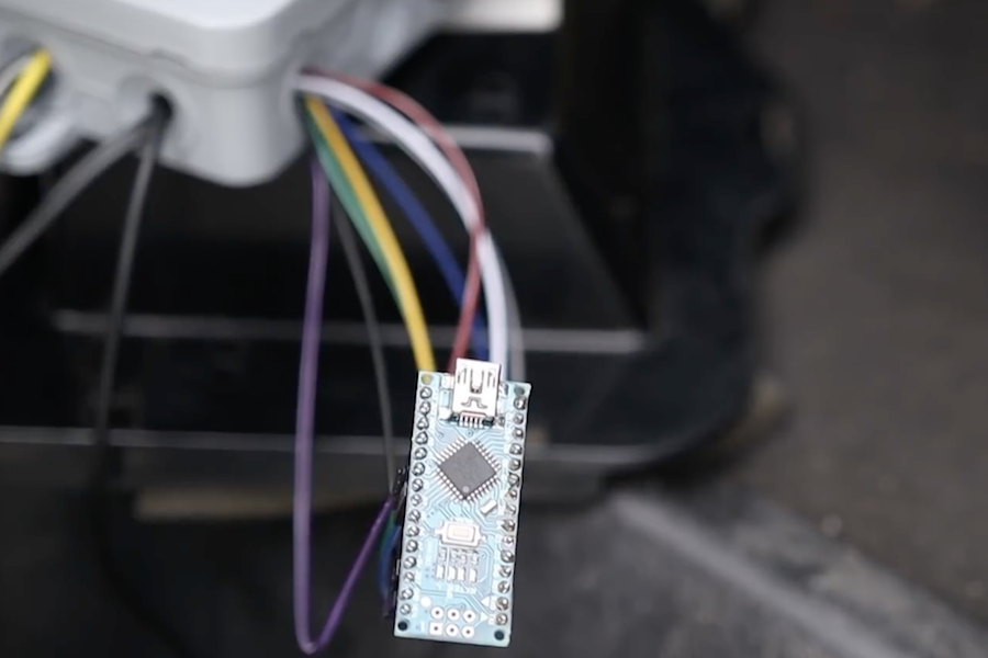
Mathis Ochsenmeier’s Analogous Door Display is exactly that. It mirrors his VW van’s front and rear doors using an Arduino Nano to take in sensor information and actuate three servo motors to mimic door positions.
Now when the van’s front doors or rear hatch open or close, the little van on the dash’s doors follow suit—both a useful diagnostic tool, and an entertaining model.
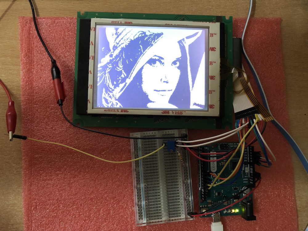
These days, you could be forgiven for thinking driving an LCD from a microcontroller is easy. Cheap displays have proliferated, ready to go on breakout boards with controllers already baked in. Load up the right libraries and you’re up and running in a matter of minutes. However, turn your attention to trying to drive a random LCD you’ve yanked out of a piece of old equipment, and suddenly things get harder. [Ivan Kostoski] was in just such a position and decided to get down to work.
[Ivan]’s LCD was a 320×240 STN device salvaged from an old tape library. The display featured no onboard controller, and the original driver wasn’t easily repurposed. Instead, [Ivan] decided to drive it directly from an Arduino Uno.
This is easier said than done. There are stringent timing requirements that push the limits of the 8-bit platform, let alone the need for a negative voltage to drive the screen and further hardware to drive the backlight. These are all tackled in turn, with [Ivan] sharing his tips to get the most flexibility out of the display. Graphics and text modes are discussed, along with optimizations that could be possible through the varied use of available RAM and flash.
While you may or may not want a gigantic backlit skull cutout haunting the wall of your workshop, this was perfect for Jay and Jamie of the “Wicked Makers” YouTube channel.
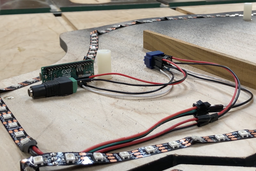
Their device is cut of two 30” squares of plywood with a CNC router. This forms a base layer that holds everything off the wall, while an outer layer provides a nice circuit/skull texture.
They affixed WS2812B LED strips to the base layer, controlled by an Arduino Micro. These strips shine off the wall for a glow through the edges, along with circuit board style cutouts inside the skull, diffused using wax paper.
Arduino code and the circuit diagram are found in the project’s write-up if you’d like to construct your own!
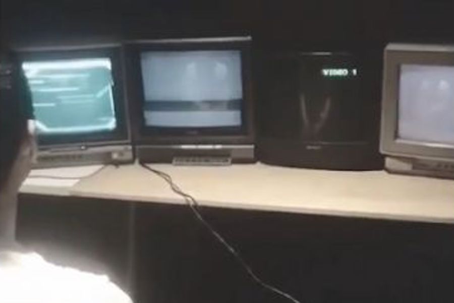
While you might see a CRT by the side of the street and think noting of it, Ryan Mason has come up with a novel use for five of them in a row called the Cathode MK1.
This set uses the Unity game engine along with an Arduino board to spread games across five tube TVs arranged side-by-side.
In order to keep project costs down, Mason’s gaming rig is restricted to displaying a game signal on one TV at a time. This makes gameplay even more interesting, especially considering that the way that each TV handles a loss of signal contributing to the experience.
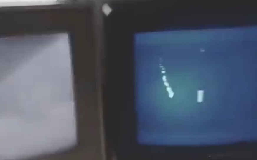
Several games are available for this unique system, including Long Pong AKA Pooooong, where a ball bounces from screen to screen as shown in the clip below.
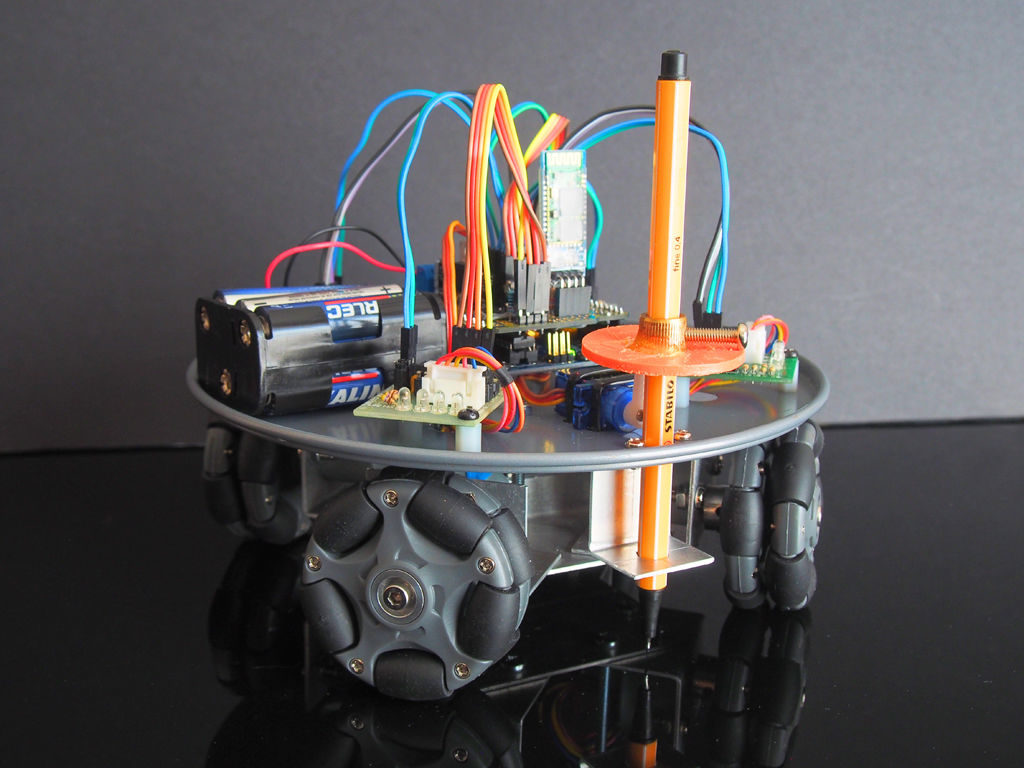
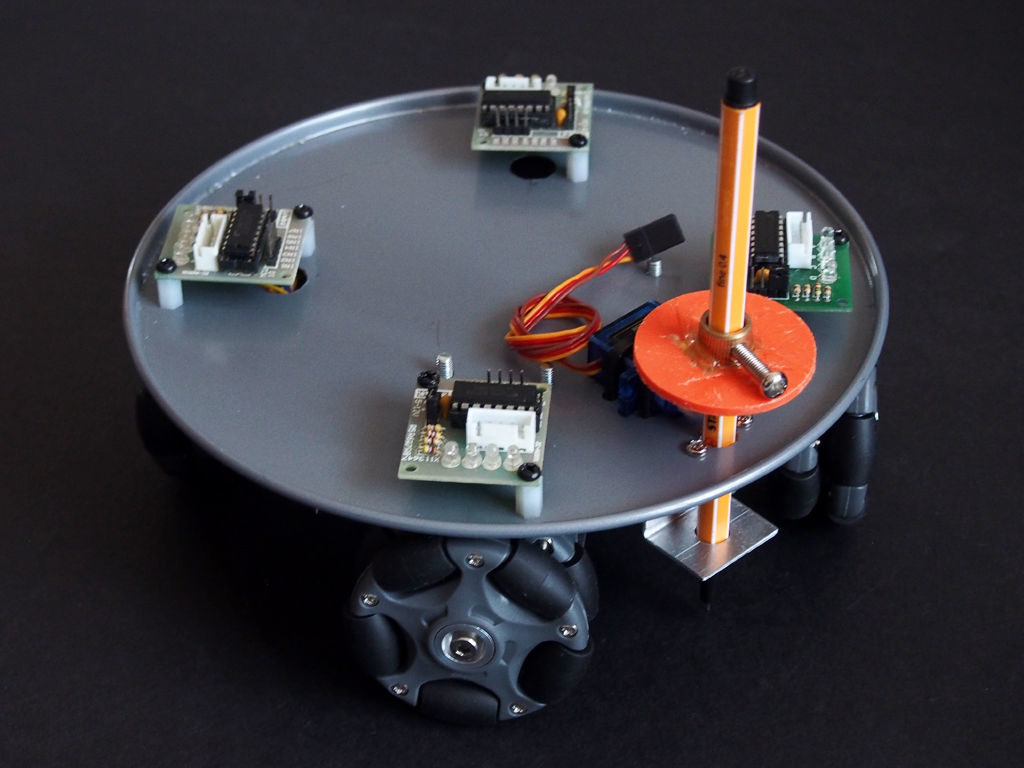
Retired maker “lingb” created an omni-bot, with four wheels that allow sliding motion in the X/Y plane courtesy of their perpendicular rollers. While that alone would have been a fun build, he also attached a pen, along with a servo-based lifting mechanism, turning this robot into a free-range plotter!
The device is controlled by an Arduino Uno and Bluetooth module, and takes movement commands via a linked smartphone or tablet. Four 28BYJ-48 stepper motors with ULN2003 drivers move each wheel, though outputs are shared between opposite motors to save on I/O.
This means that rotating the robot isn’t possible, but as shown in the video below, this isn’t needed to plot straight and curved lines with good accuracy.
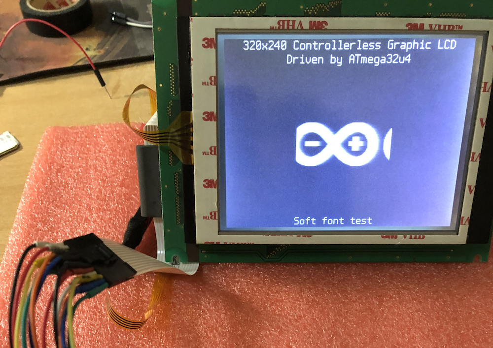
As hardware hackers, we’re always on the lookout for discarded components that can be re-purposed into something even more awesome. One such class of component that you may find is the controller-less graphics LCD modules, which can be found on old copiers, tape libraries, and the like.
This project by Ivan Kostoski shows how to drive one of these displays with a 320×240 resolution. He’s tested his code using several types of Arduino board, such as the Uno and Leonardo, using minimal external components.
Summary Repository contains code samples for driving 4-bit parallel controllerless graphics LCD (CLGLCD) module with AVR MCU on an Arduino board, using minimal external components and staying within Arduino IDE.
4-bit Controllerless Graphics LCD modules Controllerless graphics LCD modules are antiques that can be salvaged from old copiers, tape libraries, etc… They commonly are missing, well, the controller chip, the one with the memory. Don’t go buying one of these, for Arduino usage, even if you find them on sale. They are usually industrial, have poor viewing angles, generally slow response time, and pain to work-with. There, I said my peace… But if you already have one, their size (i.e. 5.7in) or simplicity can have its uses and beauty.
I have tested this code with 320×240 STN LCD monochrome module marked as F-51543NFU-LW-ADN / PWB51543C-2-V0, salvaged some time ago from retired tape library, without the controller module (which it appears is based on FPGA and wouldn’t be of much use anyway).
The same type of interface (4-bit data) with various signal names is present on many industrial modules based on multiplexed column and common row LCD drivers, like LC79401/LC79431. Or this is what is behind the controller IC. They all have some variations like LCD drive voltage (positive or negative, depending on temperature and size of the module), backlight (LED/CCFL), some logic quirks (i.e. CL2 is ignored while CL1 is up, etc…), so maybe this code can be adapted to other controllerless modules. Module’s datasheet is necessity for the connector pinouts and timing requirements. Some modules may even generate LCD drive voltage internally, and outputting it on a pin so actual V0 driving voltage can be adjusted.
More info on the build/technique is found on GitHub, where you can also download project code and find more background on how interfacing with these devices works.
Remote control cars are interesting, but as Leon van den Beukel shows in the video below, an RC forklift can be even more challenging and fun to create.
His project was constructed using a variety of hand and automated techniques, resulting in a build that can easily manipulate tiny pallets. Forks are lifted into the air via a motor and belt assembly, and tilted with a small servo.
The device uses an Arduino Mega for control, and is linked to an Android phone over Bluetooth for user interface. Code, along with STL files and drawings, are available on GitHub and the custom Android control app can be found here.
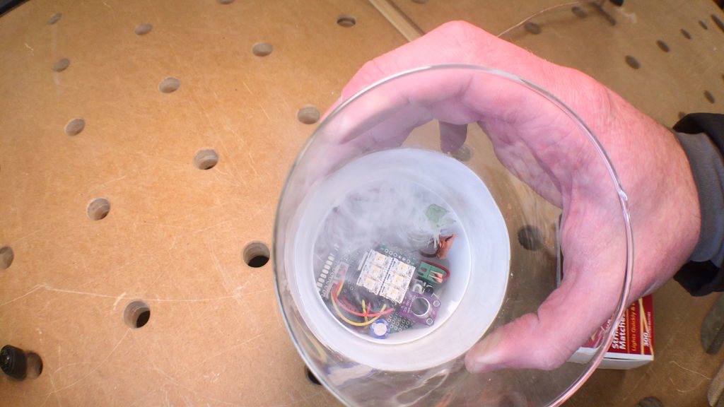
Keith of “Keith’s Test Garage” wanted an LED candle. While somewhat realistic flicking units are easy to find, he was in search of something much more like the actual thing, and after several years of work has come up with a rather amazing replica.
The device’s wax-embedded glass enclosure houses an Arduino, along with a series of six RGBW LEDs inside that randomly flicker away to simulate a flame. This effect is triggered via a real match, which is sensed by an IR module. To stop the effect, one literally blows out the candle through a microphone input that picks up on this action.
Most impressively however, upon putting out the faux flame, a length of resistive wire heats up glycerin and smelling oil on a wick, producing a puff of smoke to end the light performance.
Maker Jeremy S. Cook has experimented with both CNC machinery and light painting in the past, and decided to combine these two skills into a new artistic device.
His setup uses a web app found here to program a CNC router as a sort of dot matrix printer. But instead of a pen, pencil, brush or other marking utensil, it uses a button as an input to the onboard Arduino Nano when pressed to the router’s surface.
From this input, the Arduino then commands a diffused RGB LED to “mark” the surface with light, painting an image on the camera’s exposed sensor.
Code and print files are are available on GitHub if you’d like to try your own light art experiments!