Posts with «tronixstuff» label

Tutorial – Arduino and SIM900 GSM Modules

Use the SIM900 GSM modules with Arduino in Chapter 55 of our Arduino Tutorials. The first chapter is here, the complete series is detailed here.

Introduction

The goal of this tutorial is to illustrate various methods of interaction between an Arduino Uno (or compatible) and the GSM cellular network using a SIM900 GSM shield, with which you can then use your existing knowledge to build upon those methods.

We’ll be using a SIMCOM SIM900 GSM module shield. (If you’re looking for tutorials on the Spreadtrum SM5100 modules, start here). There must be scores of Arduino shields or modules using the SIM900, so as you can imagine each one may be a little bit different with regards to the hardware side of things – so we’re assuming you have an understanding of how hardware and software serial works as well as supply voltages and the hardware side of the Arduino world.

As for the specific shield to use, we just chose the cheapest one available at the time – which turned out to be the “SIM900 GPRS/GSM Arduino shield” from Linksprite:

However with a little research and work, the sketches provided should also work with any SIM900 module/shield and Arduino – as long as you have the appropriate serial and power settings. 

Getting Started

A little preparation goes a long way, so make sure you’ve covered the following points:

  • Regarding your cellular provider. Do you have coverage on a GSM 850 MHz, GSM 900 MHz, DCS 1800 MHz or PCS 1900 MHz network?  When we say GSM that means 2G – not 3G, 4G or LTE. Will they allow the use of non-supported devices on the network? Some carriers will block IMEI numbers that were not provided by their sales channel. Or you may have to call the provider and supply the IMEI of your GSM module to allow it on the network. Finally, it would be wise to use either a prepaid or an account that offers unlimited SMS text messaging – you don’t want any large bills if things go wrong.
  • Power. Do you have adequate power for your SIM900 module? Some shields will use more current than the Arduino can supply (up to 2A), so you may need an external high-current supply. The Linksprite shield we use needs 5V up to 2A into the onboard DC socket. Otherwise, check with your supplier.
  • Antenna. If your module/shield etc. doesn’t have an antenna – get one. You do need it.
  • Turn off the PIN lock on the SIM card. The easiest way to do this is to put the SIM in a handset and use the menu function.
  • And as always, please don’t make an auto-dialler…

Furthermore, download the SIM900 hardware manual (.pdf) and the AT command manual (.pdf), as we’ll refer to those throughout the tutorial.

Power

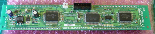
There is a DC socket on the shield, which is for a 5V power supply:

Although the data from Linksprite claims the shield will use no more than 450 mA, the SIMCOM hardware manual (page 22) for the module notes that it can draw up to 2A for short bursts. So get yourself a 5V 2A power supply and connect it via the DC socket, and also ensure the switch next to the socket is set to “EXT”.

Furthermore, you can turn the GSM module on and off with the power button on the side of the shield, and it defaults to off during an initial power-up. Therefore you’ll need to set D9 to HIGH for one second in your sketch to turn the module on (or off if required for power-saving). Don’t panic, we’ll show how this is done in the sketches below.

Software Serial

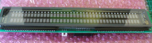
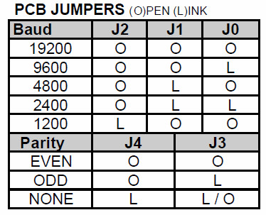
We will use the Arduino software serial library in this tutorial, and the Linksprite shield has hard-wired the serial from the SIM900 to a set of jumpers, and uses a default speed of 19200. Make sure you your jumpers are set to the “SWserial” side, as shown below:

And thus whenever an instance of SoftwareSerial is created, we use 7,8 as shown below:

SoftwareSerial SIM900(7, 8); // RX, TX

If you shield is different, you’ll need to change the TX and RX pin numbers. This also means you can’t use an Arduino Leonardo or Mega (easily).

Wow – all those rules and warnings?

The sections above may sound a little authoritarian, however we want your project to be a success. Now, let’s get started…

A quick test…

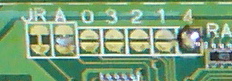
At this point we’ll check to make sure your shield and locate and connect to the cellular network. So make sure your SIM card is active with your cellular provider, the PIN lock is off, and then insert it and lock the SIM card  to the carrier on the bottom of the shield:

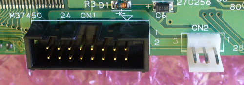
Then plug the shield into your Uno, attach 5V power to the DC socked on the GSM shield, and USB from the Uno to the PC. Press the “PWRKEY” button on the side of the shield for a second, then watch the following two LEDs:

The bright “STATUS” LED will come on, and then the “NETLIGHT” LED will blink once every 800 milliseconds- until the GSM module has found the network, at which point it will blink once every three seconds. This is shown in the following video:

Nothing can happen until that magic three-second blink – so if that doesn’t appear after a minute, something is wrong. Check your shield has the appropriate power supply, the antenna is connected correctly, the SIM card is seated properly and locked in- and that your cellular account is in order. Finally, you may not have reception in that particular area, so check using a phone on the same network or move to a different location.

Making a telephone call from your Arduino

You can have your Arduino call a telephone number, wait a moment – then hang up. This is an inexpensive way of alerting you of and consider the following sketch:

// Example 55.1

#include <SoftwareSerial.h>
SoftwareSerial SIM900(7, 8); // configure software serial port

void setup()
{
  SIM900.begin(19200);               
  SIM900power();  
  delay(20000);  // give time to log on to network. 
}

void SIM900power()
// software equivalent of pressing the GSM shield "power" button
{
  digitalWrite(9, HIGH);
  delay(1000);
  digitalWrite(9, LOW);
  delay(5000);
}

void callSomeone()
{
  SIM900.println("ATD + +12128675309;"); // dial US (212) 8675309
  delay(100);
  SIM900.println();
  delay(30000);            // wait for 30 seconds...
  SIM900.println("ATH");   // hang up
}

void loop()
{
  callSomeone(); // call someone
  SIM900power();   // power off GSM shield
  do {} while (1); // do nothing
}

The sketch first creates a software serial port, then in void setup() starts the software serial port, and also turns on the GSM shield with the function SIM900power (which simply sets D9 high for a second which is the equivalent of pressing the power button). Notice the delay function in void setup – this gives the GSM module a period of time to locate and log on to the cellular network. You may need to increase (or be able to decrease) the delay value depending on your particular situation. If in doubt, leave it as a long period.

The process of actually making the call is in the function callSomeone(). It sends a string of text to the GSM module which consists of an AT command. These are considered the “language” for modems and thus used for various tasks. We use the ATD command to dial (AT… D for dial) a number. The number as you can see in the sketch needs to be in world-format. So that’s a “+” then the country code, then the phone number with area code (without the preceding zero).

So if your number to call is Australia (02) 92679111 you would enter +61292679111. Etcetera. A carriage return is then sent to finalise the command and off it goes dialling the number. Here’s a quick video demonstration for the non-believers:

After thirty seconds we instruct the module to hand up with another AT command – “ATH” (AT… H for “hang up”), followed by turning off the power to the module. By separating the call feature into a function – you can now insert this into a sketch (plus the preceding setup code) to call a number when required.

Sending an SMS text message

This is a great way of getting data from your Arduino to almost any mobile phone in the world, at a very low cost. For reference, the maximum length of an SMS text message is 160 characters – however you can still say a lot with that size limit. First we’ll demonstrate sending an arbitrary SMS. Consider the following sketch:

// Example 55.2

#include <SoftwareSerial.h>
SoftwareSerial SIM900(7, 8);

void setup()
{
  SIM900.begin(19200);
  SIM900power();  
  delay(20000);  // give time to log on to network. 
}

void SIM900power()
// software equivalent of pressing the GSM shield "power" button
{
  digitalWrite(9, HIGH);
  delay(1000);
  digitalWrite(9, LOW);
  delay(5000);
}

void sendSMS()
{
  SIM900.print("AT+CMGF=1\r");                                                        // AT command to send SMS message
  delay(100);
  SIM900.println("AT + CMGS = \"+12128675309\"");                                     // recipient's mobile number, in international format
  delay(100);
  SIM900.println("Hello, world. This is a text message from an Arduino Uno.");        // message to send
  delay(100);
  SIM900.println((char)26);                       // End AT command with a ^Z, ASCII code 26
  delay(100); 
  SIM900.println();
  delay(5000);                                     // give module time to send SMS
  SIM900power();                                   // turn off module
}

void loop()
{
  sendSMS();
  do {} while (1);
}

The basic structure and setup functions of the sketch are the same as the previous example, however the difference here is the function sendSMS(). It used the AT command “AT+CMGF” to tell the GSM module we want to send an SMS in text form, and then “AT+CMGS” followed by the recipient’s number. Once again note the number is in international format. After sending the send SMS commands, the module needs  five seconds to do this before we can switch it off. And now for our ubiquitous demonstration video:


You can also send text messages that are comprised of numerical data and so on – by compiling the required text and data into a string, and then sending that. Doing so gives you a method to send such information as sensor data or other parameters by text message.

For example, you might want to send daily temperature reports or hourly water tank levels. For our example, we’ll demonstrate how to send a couple of random numbers and some text as an SMS. You can then use this as a framework for your own requirements. Consider the following sketch:

// Example 55.3

#include <SoftwareSerial.h>
SoftwareSerial SIM900(7, 8);
int x,y;
String textForSMS;

void setup()
{
  SIM900.begin(19200);
  SIM900power();  
  delay(20000);  // give time to log on to network. 
  randomSeed(analogRead(0));
}

void SIM900power()
// software equivalent of pressing the GSM shield "power" button
{
  digitalWrite(9, HIGH);
  delay(1000);
  digitalWrite(9, LOW);
  delay(7000);
}

void sendSMS(String message)
{
  SIM900.print("AT+CMGF=1\r");                     // AT command to send SMS message
  delay(100);
  SIM900.println("AT + CMGS = \"+12128675309\"");  // recipient's mobile number, in international format
  delay(100);
  SIM900.println(message);                         // message to send
  delay(100);
  SIM900.println((char)26);                        // End AT command with a ^Z, ASCII code 26
  delay(100); 
  SIM900.println();
  delay(5000);                                     // give module time to send SMS
  SIM900power();                                   // turn off module
}

void loop()
{
  x = random(0,255);
  y = random(0,255);
  textForSMS = "Your random numbers are ";
  textForSMS.concat(x);
  textForSMS = textForSMS + " and ";
  textForSMS.concat(y);
  textForSMS = textForSMS + ". Enjoy!";  
  sendSMS(textForSMS);
  do {} while (1);
}

Take note of the changes to the function sendSMS(). It now has a parameter – message, which is a String which contains the text to send as an SMS. In void loop() the string variable textForSMS is constructed. First it contains some text, then the values for x and y are added with some more text. Finally the string is passed to be sent as an SMS. And here it is in action:

Conclusion

After working through this tutorial you should have an understanding of how the basics of the GSM shield and AT commands work. If there’ s demand we’ll continue with more features and possibilities in a future tutorial, so let us know via the contact page.  And if you enjoyed the tutorial, or want to introduce someone else to the interesting world of Arduino – check out my book (now in a third printing!) “Arduino Workshop” from No Starch Press.

In the meanwhile have fun and keep checking into tronixstuff.com. Why not follow things on twitterGoogle+, subscribe  for email updates or RSS using the links on the right-hand column? And join our friendly Google Group – dedicated to the projects and related items on this website. Sign up – it’s free, helpful to each other –  and we can all learn something.

The post Tutorial – Arduino and SIM900 GSM Modules appeared first on tronixstuff.

Tronixstuff 18 Sep 03:33

Kit Review – Maniacal Labs Epoch Clock

Introduction

The subject of our latest kit review is the “Epoch Clock” from Maniacal Labs, a new organisation started by three young lads with some interesting ideas. Regular readers will know we love a clock – so when the opportunity came to review this one, we couldn’t say no.

At this point you may be thinking “what is Epoch time anyway?”. Good question! It is the number of seconds elapsed since the first of January, 1970 (UTC) – and used by Unix-based computers as the start of their time universe. (For more on the theory of Epoch time, check out Wikipedia). For example – 1379226077 Epoch time is Sun, 15 Sep 2013 06:21:17 GMT. That’s a lot of seconds. If you’re curious, you can do more calculations with the EpochTime website.

Moving forward, this clock kit will show Epoch time in full 32-bit binary glory, using a DS1307 real-time clock IC (with backup battery) and is controlled with an ATmega328P-PU – so you can modify the code easily with the Arduino IDE or WinAVR (etc).

Assembly

The creators have spent a lot of time on not only the packaging and out-of-box-experience, but also the documentation and setup guide – so as long as you’re fine with simple through-hole soldering the kit will not present any challenges. The kit arrives in a sturdy box:

… with well packaged components. Everything is included for the finished product, as well as IC sockets, the RTC backup battery and a USB cable so you can power the clock from a USB hub:

The PCB is a good thickness, and has a clear silk-screen and solder mask:

Construction is simple, just follow the step-by-step instructions. Starting with the USB socket for power:

… then the resistors:

… the LEDs:

… all 32 of them. Note that the LEDs don’t sit flush with the PCB, so a little effort is required to keep them aligned:

 Then the rest of the components just fit as expected. I’ve also added the included header pins for an FTDI programming cable and ICSP to keep my options open:

Then simply fit the battery, insert the ICs and you’re done:

Using the clock

The microcontroller is pre-programmed, so you can use the clock straight away. You will however need to set the time first. To make this incredibly easy, there is a special web page that displays the current time and Epoch time, which steps you through the process of setting the time using the buttons.

Or with some code available on the kit github page and a programming cable, you can automatically sync it to the clock. Once setup, the battery will keep the current time in the RTC nicely. The clock is powered by 5V, which is easily supplied with the included USB cable, or you can always hack in your own feed.

So what does Epoch time in 32-bit binary look like? Here’s a short video of the clock in action:

Reading the time requires converting the binary number displayed with the LEDs back to a decimal number – which is of course the Epoch count of seconds since 1/1/1970. Math teachers will love this thing.

But wait, there’s more!

If you get tired of the blinking, there’s a test function which is enabled by holding down both buttons for a second, which turns the Epoch Clock into a nifty Larson Scanner:

To create your own sketches or examine the design files in more detail, it’s all on the clock github page. From a hardware perspective you have an ATmega328P-PU development board with a DS1307 battery-backed real-time clock – with 32 LEDs. So you could also create your own kind of clock or other multi-LED blinking project without too much effort. Review the EpochClockSchematic (.pdf) to examine this in more detail.

Conclusion

I really enjoyed this kit – it was easy to assemble, I learned something new and frankly the blinking LEDs can be quite soothing. The clock would make a great for a conversation-starter in the office, or would make an ideal gift for any Sheldon Cooper-types you might be associated with. Or have competitions to see who can convert the display to normal time. After shots.

Nevertheless it’s a fun and imaginative piece of kit, fully Open Hardware-compliant – and if you’ve made it this far – get some and have fun. Full-sized images are on flickr. Interested in Arduino? Check out my new book “Arduino Workshop” from No Starch Press.

In the meanwhile have fun and keep checking into tronixstuff.com. Why not follow things on twitterGoogle+, subscribe  for email updates or RSS using the links on the right-hand column? And join our friendly Google Group – dedicated to the projects and related items on this website. Sign up – it’s free, helpful to each other –  and we can all learn something.

[Note – The kit reviewed was a promotional consideration from Maniacal Labs]

The post Kit Review – Maniacal Labs Epoch Clock appeared first on tronixstuff.

Tronixstuff 15 Sep 10:29

Tutorial – LM3914 Dot/Bar Display Driver IC

Introduction

This is the first of three tutorials that will examine the LM391x series of LED driver ICs. In this first tutorial we cover the LM3914, then the LM3915 and LM3916 will follow. The goal of these tutorials is to have you using the parts in a small amount of time and experiment with your driver ICs, from which point you can research further into their theory and application.

Although these parts have been around for many years, the LM3914 in particular is still quite popular. It offers a simple way to display a linear voltage level using one or more groups of ten LEDs with a minimum of fuss.

With a variety of external parts or circuitry these LEDs can then represent all sorts of data, or just blink for your amusement. We’ll run through a few example circuits that you can use in your own projects and hopefully give you some ideas for the future. Originally by National Semiconductor, the LM391X series is now handled by Texas Instruments.

Getting Started

You will need the LM3914 data sheet, so please download that and keep it as a reference. So – back to basics. The LM3914 controls ten LEDs. It controls the current through the LEDs with the use of only one resistor, and the LEDs can appear in a bar graph or single ‘dot’ when in use. The LM3914 contains a ten-stage voltage divider, each stage when reached will illuminate the matching LED (and those below it in level meter mode).

Let’s consider the most basic of examples (from page two of the data sheet) – a voltmeter with a range of 0~5V:


The Vled rail is also connected to the supply voltage in our example. Pin 9 controls the bar/dot display mode – with it connected to pin 3 the LEDs will operate in bar graph mode, leave it open for dot mode. The 2.2uF capacitor is required only when “leads to the LED supply are 6″ or longer”. We’ve hooked up the circuit above, and created a 0~5V DC source via a 10kΩ potentiometer with a multimeter to show the voltage – in the following video you can see the results of this circuit in action, in both dot and bar graph mode:

Customising the upper range and LED current

Well that was exciting, however what if you want a different reference voltage? That is you want your display to have a range of 0~3 V DC? And how do you control the current flow through each LED? With maths and resistors. Consider the following formulae:

As you can see the LED current (Iled) is simple, our example is 12.5/1210 which returned 10.3 mA – and in real life 12.7 mA (resistor tolerance is going to affect the value of the calculations).

Now to calculate a new Ref Out voltage – for example  we’ll shoot for a 3 V meter, and keep the same current for the LEDs. This requires solving for R2 in the equation above, which results with R2 = -R1 + 0.8R1V. Substituting the values – R2 = -1210 + 0.8 x 1210 x 3 gives a value of 1694Ω for R2. Not everyone will have the E48 resistor range, so try and get something as close as possible. We found a 1.8 kΩ for R2 and show the results in the following video:

You can of course have larger display range values, but a supply voltage of no more than 25 V will need to be equal to or greater than that value. E.g. if you want a 0~10 V display, the supply voltage must be >= 10V DC.

Creating custom ranges

Now we’ll look at how to create  a lower range limit, so you can have displays that (for example) can range from a non-zero positive value. For example, you want to display levels between 3 and 5V DC. From the previous section, you know how to set the upper limit, and setting the lower limit is simple – just apply the lower voltage to pin 4 (Rlo).

You can derive this using a resistor divider or other form of supply with a common GND. When creating such circuits, remember that the tolerance of the resistors used in the voltage dividers will have an affect on the accuracy. Some may wish to fit trimpots, which after alignment can be set permanently with a blob of glue.

Finally, for more reading on this topic – download and review the TI application note.

Chaining multiple LM3914s

Two or more LM3914s can be chained together to increase the number of LEDs used to display the levels over an expanded range. The circuitry is similar to using two independent units, except the REFout (pin 7) from the first LM3914 is fed to the REFlo (pin 4) of the second LM3914 – whose REFout is set as required for the upper range limit. Consider the following example schematic which gave a real-world range of 0~3.8V DC:

The 20~22kΩ resistor is required if you’re using dot mode (see “Dot mode carry” in page ten of the data sheet). Moving on, the circuit above results with the following:

Where to from here?

Now you can visually represent all sorts of low voltages for many purposes. There’s more example circuits and notes in the LM3914 data sheet, so have a read through and delve deeper into the operation of the LM3914. Furthermore Dave Jones from eevblog.com has made a great video whcih describes a practical application of the LM3914:

Conclusion

As always I hope you found this useful. Don’t forget to stay tuned for the second and third instalments using the LM3915 and LM3916. Full-sized images are on flickr. And if you made it this far – check out my new book “Arduino Workshop” from No Starch Press.

In the meanwhile have fun and keep checking into tronixstuff.com. Why not follow things on twitterGoogle+, subscribe  for email updates or RSS using the links on the right-hand column? And join our friendly Google Group – dedicated to the projects and related items on this website. Sign up – it’s free, helpful to each other –  and we can all learn something.

The post Tutorial – LM3914 Dot/Bar Display Driver IC appeared first on tronixstuff.

Tronixstuff 13 Sep 15:13
bar  display  dot  driver  electronics  example  ic  led  level  lm3914  lm3915  lm3916  ti  tronixstuff  tutorial  voltmeter  

Using older Noritake Itron VFD modules

Introduction

Now and again you come across interesting parts on ebay, from friends or just rooting around in second-hand stores. One example of this was a huge Noritake Itron 40 x 2 character vacuum-fluorescent display from 1994 (or earlier) which was passed on from a client. Originally it looked quite complex, however after spending some time the data sheets were found and it was discovered to have a simple serial interface – and with a little work we’ve got it working, so read on if you’re interested in classic VFDs or have a similar unit.

Getting Started

The model number for our display is CU40026SCPB-T20A. Here’s a quick walk-around, the front:

… the back:

… the interfaces:

… and configuration jumpers:

The serial interface baud rate is determined by the jumpers (above), for example:

So comparing the table above against the jumpers on our module gives us a data speed of 19200 bps with no parity. Great – we can easily create such a connection with a microcontroller with a serial output and 5V logic levels; for our examples we’ll use an Arduino-compatible board.

Wiring up the VFD is simple – see the white jumpers labelled CN2 as shown previously. Pin 1 is 5V (you need an external supply that can offer up to 700 mA), pin 2 to Arduino digital pin 7, and pin 3 to Arduino and power supply GND. We use Arduino D7 with software serial instead of TX so that the display doesn’t display garbage when a sketch is being uploaded. Then it’s a matter of simply sending text to the display, for example here’s a quick demonstration sketch:

// Working with Noritake Itron VFD modules - model CU40026SCPB-T20A
// John Boxall 2013

#include <SoftwareSerial.h>
SoftwareSerial VFD(6,7); // RX, TX

void setup()
{
  VFD.begin(19200);
}

void loop()
{
  VFD.print("Hello, world. This is a Noritake VFD "); // You can blast out text 
  do {} while (1);
}

… and the results:

If you’re not keen on the colour or intensity of the display, try some Perspex over the top – for example:

Controlling the display

At this point you’ll need the data sheet, there’s a couple you can download: data sheet onedata sheet two. As you saw previously, writing text is very simple – just use .print functions. However you may want to send individual characters, as well as special commands to control aspects of the display. These are outlined in the data sheet – see the “Software Commands” and “Character Fonts” tables.

If you need to send single commands – for example “clear display” which is 0x0E, use a .write command, such as:

VFD.write(0x0E); // clear display

Some commands are in the format of escape codes (remember those?) so you need to send ESC then the following byte, for example to change the brightness to 50%:

VFD.write(0x1B); // ESC
    VFD.write(0x4C); // brightness
    VFD.write(0x40); // 50% brightness

Armed with that knowledge and the data sheets you can now execute all the commands. According to the data sheet it is possible to change fonts however no matter what the hardware jumper or command we tried it wouldn’t budge from the Japanese katakana font. Your screen may vary. If you use the “screen priority write” function heed the data sheet with respect to the extended “busy” time by delaying subsequent writes to the display by a millisecond.

 Putting it all together

Instead of explaining each and every possible command, I’ve put the common ones inside documented functions in the demonstration sketch below, which is followed by a quick video of the sketch in operation.

// Working with Noritake Itron VFD modules - model CU40026SCPB-T20A
// John Boxall 2013

#include <SoftwareSerial.h>
SoftwareSerial VFD(6,7); // rx, tx

void setup()
{
  VFD.begin(19200); // set speed for software serial port 
  resetVFD();  
  VFDclearsceen();
//  VFD.write(0x12); // vertical scroll mode (on)
}

void resetVFD()
// performs a software reset on the VFD controller
{
  VFD.write(0x1B); // ESC
  VFD.write(0x49); // software reset
}

void VFDnewline()
// moves cursor to start of next line
{
  VFD.write(0x0D); // carriage return
  VFD.write(0x0A); // line feed
}

void VFDclearsceen()
// moves cursor to top-left and clears display
{
  VFD.write(0x0E); // clear display 
  VFD.write(0x0C); // form feed - cursor to top-left
}

void VFDbrightness(int amount)
// sets VFD brightness - 25/50/75/100%
// uses ESC sequences
{
  switch(amount)
  {
  case 25:
    VFD.write(0x1B); // ESC
    VFD.write(0x4C); // brightness
    VFD.print(0); // 25% brightness
    break;
  case 50:
    VFD.write(0x1B); // ESC
    VFD.write(0x4C); // brightness
    VFD.write(0x40); // 50% brightness
    break;
  case 75:
    VFD.write(0x1B); // ESC
    VFD.write(0x4C); // brightness
    VFD.write(0x80); // 75% brightness
    break;
  case 100:
    VFD.write(0x1B); // ESC
    VFD.write(0x4C); // brightness
    VFD.write(0xC0); // 100% brightness
  }
}

void VFDchars()
// run through characters for selected font
{
  for (int i = 21 ; i < 256; i++)
  {
    VFD.write(0x16); // underline cursor off
    VFD.write(i);
    delay(100);
  }
}

void moveCursor(byte position)
// moves the cursor - top row is 0~39, bottom row is 40~79
// vertical scroll mode must be turned off if used
{
    VFD.write(0x1B); // ESC
    VFD.write(0x48); // move cursor 
    VFD.write(position); // location
}

void loop()
{
  VFD.write(0x16); // underline cursor off
  VFD.print("Hello, world - line one."); // You can blast out text 
  delay(1000);      
  VFDnewline();
  VFD.print("Hello, world - line two."); 
  delay(1000);    
  VFDclearsceen();
  VFDbrightness(25);
  VFD.print("*** 25% brightness ***");   
  delay(1000);
  VFDclearsceen();  
  VFDbrightness(50);
  VFD.print("*** 50% brightness ***");     
  delay(1000);
  VFDclearsceen();   
  VFDbrightness(75);
  VFD.print("*** 75% brightness ***");       
  delay(1000);
  VFDclearsceen();   
  VFDbrightness(100);
  VFD.print("*** 100% brightness ***");         
  delay(1000);
  VFDclearsceen();

  VFDchars();
  VFDclearsceen();

  for (int i = 0; i < 80; i++)
  {
    VFD.write(0x16); // underline cursor off
    moveCursor(i);
    VFD.print("X");
    delay(100);
    moveCursor(i);    
    VFD.print(" ");    
  }
  VFDclearsceen();
}


Conclusion

We hope you found this interesting and helpful. And if you have an inexpensive source for these old displays, let us know in the comments. Full-sized images are on flickr. And if you made it this far – check out my new book “Arduino Workshop” from No Starch Press.

In the meanwhile have fun and keep checking into tronixstuff.com. Why not follow things on twitterGoogle+, subscribe  for email updates or RSS using the links on the right-hand column? And join our friendly Google Group – dedicated to the projects and related items on this website. Sign up – it’s free, helpful to each other –  and we can all learn something.

The post Using older Noritake Itron VFD modules appeared first on tronixstuff.

Build an Arduino-controlled Larson Scanner

Introduction

For fun and a little bit of learning, let’s make a Larson Scanner. This isn’t a new project, for example we reviewed a kit in the past – however after finding some large LEDs we decided to make our own version. We’ll use an Arduino-compatible circuit to control the LEDs, and explain both the hardware and required Arduino sketch – then build a temporary small and a more permanent large version (and a bonus project).

So what is a Larson Scanner anyway? Named in honour of Glen A. Larson the creator of television shows such as Battlestar Galactica and Knight Rider – as this kit recreates the left and right blinking motion used in props from those television shows. For example:

Making your own is quite simple, it’s just eight LEDs or lamps blinking in a certain order. If you’re not familiar with the Arduino hardware, please have a quick review of this tutorial before continuing.

Small version

If you’re just interested in whipping up a solderless breadboard or small version, it will take less than fifteen minutes. Just get an Arduino Uno or compatible board and construct the following circuit (the resistors are 560Ω):

The sketch is also very simple. There are two ways to address those digital output pins, and to save sanity and clock cycles we’re going to use port manipulation instead of many digitalWrite() functions. So for our circuit above, enter and upload the following sketch:

// Simple Arduno LED back-and-forth effects, similar to "KITT" from "Knight Rider"
// Original idea by Glen A. Larson 
// Arduino sketch - John Boxall 2013

int del=75; // delay between LED movements

void setup()
{
  DDRD = B11111111; // D0~D7 outputs
}

void loop()
{
  PORTD = B00000001; 
  delay(del);
  PORTD = B00000011; 
  delay(del);
  PORTD = B00000111;   
  delay(del);
  PORTD = B00001110; 
  delay(del);  
  PORTD = B00011100; 
  delay(del);  
  PORTD = B00111000; 
  delay(del);  
  PORTD = B01110000; 
  delay(del);  
  PORTD = B11100000; 
  delay(del);  
  PORTD = B11000000; 
  delay(del);  
  PORTD = B10000000; 
  delay(del);  
  PORTD = B11000000; 
  delay(del);  
  PORTD = B11100000; 
  delay(del);  
  PORTD = B01110000;   
  delay(del);  
  PORTD = B00111000;   
  delay(del);  
  PORTD = B00011100;   
  delay(del);  
  PORTD = B00001110;   
  delay(del);  
  PORTD = B00000111;   
  delay(del);  
  PORTD = B00000011;   
  delay(del);  
}

Notice how the ones and zeros in the byte send to PORTD (digital pins 7~0) represent the “movement” of the scanner? You’d have to agree this is a better method of addressing the LEDs. Have some fun and experiment with the patterns you can generate and also the delay. In the following video we’ve quickly demonstrated the circuit on a solderless breadboard using different delay periods:

Large Version

Now to make something more permanent, and much larger. There are many ways of completing this project, so the following version will be a design narrative that you can follow to help with planning your own. The first consideration will be the LEDs you want to use. For our example we used some Kingbright DLC2-6SRD 20mm bright red versions we had in stock:

However you can use what you have available. The key to success will be driving the LEDs at their maximum brightness without damage. So you need to find out the best forward voltage and current for the LEDs, then do some basic mathematics. From our example LEDs’ data sheet, the maximum brightness is from 60 mA of current, at just under 6 V. A quick connection to a variable power supply shows the LEDs at this setting:

We can’t get this kind of brightness from our Arduino 5V circuit, so instead we’ll increase the circuit supply voltage to 9V and use resistors to reduce the current for the LEDs. To find the resistor value, use the following:

… where Vs is the supply voltage (9), VLED is the forward voltage for the LED (5.6), and ILED is the forward current (60 mA). The value for R is 56.66 Ω – however you can’t get that value, so 68 Ω will be the closest value from the supplier. Finally, the power of the resistor required (in watts) is calculated by W = VA. So W = 3.4 (voltage drop over resistor) * 0.06 = 0.204 W. So we’ll need 68 Ω 0.25 W resistors for our LEDs. Thus instead of running the LED straight off a digital output, it will be switched on and off via a simple BC548 transistor – shown in the following schematic example:

The digital output for each LED is connected to the 1k Ω resistor and thus switches the transistor on to allow the current to flow through the LED when required. This is repeated for each LED we intend to use – which for the case of our large scanner project is six. (Why six? Someone bought a board which was too narrow for eight…) Next is the Arduino-compatible circuit. Timing isn’t critical so we’ll save components by using a ceramic resonator instead of a crystal and two capacitors. And as shown below (note that although the image on the microcontroller says ATmega168, we’ll use an ATmega328P):

(If you’re not up for making your own Arduino-compatible circuit, there’s plenty of alternative small boards you can use such as the Nano or LeoStick). Although the symbol for Y1 (the resonator) looks complex, it’s just a resonator – for example:

the centre pin goes to GND and the outside pins go to XTAL1 and XTAL2 on the microcontroller. It isn’t polarised so either direction is fine.

At this point you may also want to consider how you’ll upload and update sketches on the project. One method is to mount the microcontroller in a socket, and just yank it between an Arduino board to upload the sketch, and then put it back in the project board. If you use this method then you’ll need a microcontroller with the Arduino bootloader.  However a more civilised method is to add ICSP header pins – they’re the 2 x 3 pins you see on most boards, for example:

With which you can use a USBASP programmer to connect your board directly to a computer just like a normal Arduino. Just use Ctrl-Shift-U to upload your sketch via the programmer. Furthermore you can use bare microcontrollers without the bootloader, as all the necessary code is included with the direct upload. So if this method interests you, add the following to your circuit:

The RESET pin is connected to pin 1 of the microcontroller. Speaking of which, if you’re unsure about which pins on the ATmega328P are which, a variety of suppliers have handy labels you can stick on top, for example:

At this point it’s time to put it all together. We’re using a random piece of prototyping PCB, and your final plan will depend on your board. As an aside, check out the Lochmaster stripboard planning software if you use stripboard a lot. As mentioned earlier your final schematic will vary depending on the number of LEDs, their requirements with respect to current and your choice of Arduino platform. By now you have the knowledge to plan the circuit yourself. After some work here’s our final board:

… and the scanner in action. We used the same sketch as for the temporary version – however reduce it to six outputs (D0~5) to match the LEDs.

 Bonus project – Electronic Die

What else can you do with six LEDs? Make an electronic die! Here’s a simple sketch that simply picks a random number every five seconds. The random number generator is seeded from unused an analogue input pin.

// Simple Arduno LED die using Larson Scanner hardware described in http://wp.me/p3LK05-36m 
// John Boxall 2013

int del=5000; // delay between new rolls
int num;

byte  digits[] = { B00000001, 
                   B00000010, 
                   B00000100, 
                   B00001000,
                   B00010000,
                   B00100000 };

void setup()
{
  randomSeed(analogRead(0)); // reseed the random number generator with some noise
  DDRD = B11111111; // D0~D7 outputs
}

void rollDie()
{
  for (int i = 0; i< 20; i++)
  {
    num = random(0,6);
    PORTD = digits[num];
    delay(50);
  }
}

void pickNumber()
{
  num = random(0,5);
  PORTD = digits[num];
  delay(1000);
}

void loop()
{
  rollDie();
  pickNumber();
}

And a quick video of our die in action:

Conclusion

We hope you found this interesting and at least made a temporary scanner on a breadboard – or at least learned something. Kudos if you went ahead and made a larger one. If you made a video, share it with us in the comments. And if you made it this far – check out my new book “Arduino Workshop” from No Starch Press.

In the meanwhile have fun and keep checking into tronixstuff.com. Why not follow things on twitterGoogle+, subscribe  for email updates or RSS using the links on the right-hand column? And join our friendly Google Group – dedicated to the projects and related items on this website. Sign up – it’s free, helpful to each other –  and we can all learn something.

The post Build an Arduino-controlled Larson Scanner appeared first on tronixstuff.

Tronixstuff 22 Aug 01:13

Tutorial – Arduino and PCF8563 real time clock IC

Use the NXP PCF8563 real-time clock IC with Arduino in chapter fifty-four of our Arduino Tutorials. The first chapter is here, the complete series is detailed here.

Updated 20/08/2013

Introduction

Recently a few people have been asking about the PCF8563 real-time clock IC from NXP – so this is a tutorial on how to use it for time, date, alarm clock and square-wave generation purposes.

The PCF8563 is another inexpensive RTC that can be used with an Arduino or other platforms due to the wide operating voltage (1 to 5.5V DC), I2C interface, and very low power consumption (when powered by a backup battery it only draws 0.25 μA). If you aren’t up to speed on the I2C interface, please review the I2C tutorials before moving forward. And please download the data sheet (.pdf).

The PCF8563 is available in various chip packages, for the curious we’re using the TSSOP8 version mounted on a breakout board:

Don’t panic – you can also get it in a breadboard-friendly DIP (through-hole) package as well, and also on a pre-built module from the usual suspects.

Demonstration Circuit

If you have a pre-made module, you can skip to the next section. However if you’re making up the circuit yourself, you will need:

  • One 32.768 kHz crystal
  • Two 1N4148 diodes*
  • One 3V coin cell (with holder)*
  • Two 10kΩ resistors
  • One 0.1 uF capacitor

And here’s the schematic:

* You can skip the diodes and battery if you don’t want a backup power supply when the main power is turned off or removed. Pin 3 is for the interrupt output (we’ll consider that later) and pin 7 is for the square-wave oscillator output.

Communicating with the PCF8563

Now to get down into the land of I2C once more. When looking through the data sheet NXP mentions two bus addresses, which have the same 7-bits finished with either a 1 for read or 0 for write. However you can just bitshift it over one bit as we don’t need the R/W bit – which gives you a bus address of 0x51.

Next you need to know which registers store the time and date – check the register map (table 4) on page 7 of the data sheet:

 There will be a few other registers of interest, but we’ll return to those later. For now, note that the time and date start from 0x02. And one more thing – data is stored in the BCD (binary-coded- decimal) format. But don’t panic, we have a couple of functions to convert numbers between BCD and decimal.

Writing the time and date is a simple matter of collating the seconds, minutes, hours, day of week, day of month, month and year into bytes, converting to BCD then sending them to the PCF8563 with seven Wire.write() functions. Reading the data is also easy, just set the pointer to 0x02 and request seven bytes of data – then run them through a BCD to decimal conversion. With a catch.

And that catch is the need to sort out unwanted bits. Revisit table 4 in the data sheet – if you see an x that’s an unused bit. If any of them are a 1 they will mess up the BCD-decimal conversion when reading the register, so they need to be eliminated just like a whack-a-mole. To do this, we perform an & (bitwise AND) operation on the returned byte and mask out the unwanted bits with a zero. How does that work?

Example – the byte for dayOfMonth is returned – we only need bits 5 to 0. So 6 and 7 are superfluous. If you use (dayOfMonth & B00111111) the & function will set bits 6 and 7 to zero, and leave the other bits as they were.

Now to put all that together in a demonstration sketch. It puts everything mentioned to work and simply sets the time to the PCF8563, and then returns it to the serial monitor. The data is kept in global variables declared at the start of the sketch, and the conversions between BCD and decimal are done “on the fly” in the functions used to send or retrieve data from the PCF8563. Read through the following sketch and see how it works for yourself:

// Example 54.1 - PCF8563 RTC write/read demonstration

#include "Wire.h"
#define PCF8563address 0x51

byte second, minute, hour, dayOfWeek, dayOfMonth, month, year;
String days[] = {"Sunday", "Monday", "Tuesday", "Wednesday", "Thursday", "Friday", "Saturday" };

byte bcdToDec(byte value)
{
  return ((value / 16) * 10 + value % 16);
}

byte decToBcd(byte value){
  return (value / 10 * 16 + value % 10);
}

void setPCF8563()
// this sets the time and date to the PCF8563
{
  Wire.beginTransmission(PCF8563address);
  Wire.write(0x02);
  Wire.write(decToBcd(second));  
  Wire.write(decToBcd(minute));
  Wire.write(decToBcd(hour));     
  Wire.write(decToBcd(dayOfMonth));
  Wire.write(decToBcd(dayOfWeek));  
  Wire.write(decToBcd(month));
  Wire.write(decToBcd(year));
  Wire.endTransmission();
}

void readPCF8563()
// this gets the time and date from the PCF8563
{
  Wire.beginTransmission(PCF8563address);
  Wire.write(0x02);
  Wire.endTransmission();
  Wire.requestFrom(PCF8563address, 7);
  second     = bcdToDec(Wire.read() & B01111111); // remove VL error bit
  minute     = bcdToDec(Wire.read() & B01111111); // remove unwanted bits from MSB
  hour       = bcdToDec(Wire.read() & B00111111); 
  dayOfMonth = bcdToDec(Wire.read() & B00111111);
  dayOfWeek  = bcdToDec(Wire.read() & B00000111);  
  month      = bcdToDec(Wire.read() & B00011111);  // remove century bit, 1999 is over
  year       = bcdToDec(Wire.read());
}

void setup()
{
  Wire.begin();
  Serial.begin(9600);
  // change the following to set your initial time
  second = 0;
  minute = 28;
  hour = 9;
  dayOfWeek = 2;
  dayOfMonth = 13;
  month = 8;
  year = 13;
  // comment out the next line and upload again to set and keep the time from resetting every reset
  setPCF8563();
}

void loop()
{
  readPCF8563();
  Serial.print(days[dayOfWeek]); 
  Serial.print(" ");  
  Serial.print(dayOfMonth, DEC);
  Serial.print("/");
  Serial.print(month, DEC);
  Serial.print("/20");
  Serial.print(year, DEC);
  Serial.print(" - ");
  Serial.print(hour, DEC);
  Serial.print(":");
  if (minute < 10)
  {
    Serial.print("0");
  }
  Serial.print(minute, DEC);
  Serial.print(":");  
  if (second < 10)
  {
    Serial.print("0");
  }  
  Serial.println(second, DEC);  
  delay(1000);
}

And a quick video of this in operation:

If all you need to do is write and read the time with the PCF8563, you’re ready to go. However there’s a few more features of this unassuming little part which you might find useful, so at least keep reading…

Square-wave output

As with any clock or RTC IC, an oscillator is involved, and as mentioned earlier you can take this from pin 7 of the PCF8563. However – it’s an open-drain output – which means current flows from the supply voltage into pin 7. For example if you want to blink an LED, connect a 560Ω resistor between 5V and the anode of the LED, then connect the cathode to pin 7 of the PCF8563.

The frequency is controlled from the register at 0x0D. Simply write one of the following values for the respective frequencies:

  • 10000000 for 32.768 kHz;
  • 10000001 for 1.024 kHz;
  • 10000010 for 32 kHz;
  • 10000011 for 1 Hz;
  • 0 turns the output off and sets it to high impedance.

The following is a quick demonstration sketch which runs through the options:

// Example 54.2 - PCF8563 square-wave generator (signal from pin 7)

#include "Wire.h"
#define PCF8563address 0x51

void PCF8563oscOFF()
// turns off oscillator
{
  Wire.beginTransmission(PCF8563address);
  Wire.write(0x0D);
  Wire.write(0);
  Wire.endTransmission();
}

void PCF8563osc1Hz()
// sets oscillator to 1 Hz
{
  Wire.beginTransmission(PCF8563address);
  Wire.write(0x0D);
  Wire.write(B10000011);
  Wire.endTransmission();
}

void PCF8563osc32Hz()
// sets oscillator to 32 kHz
{
  Wire.beginTransmission(PCF8563address);
  Wire.write(0x0D);
  Wire.write(B10000010);
  Wire.endTransmission();
}

void PCF8563osc1024kHz()
// sets oscillator to 1.024 kHz
{
  Wire.beginTransmission(PCF8563address);
  Wire.write(0x0D);
  Wire.write(B10000001);
  Wire.endTransmission();
}

void PCF8563osc32768kHz()
// sets oscillator to 32.768 kHz
{
  Wire.beginTransmission(PCF8563address);
  Wire.write(0x0D);
  Wire.write(B10000000);
  Wire.endTransmission();
}

void setup()
{
  Wire.begin();
}

void loop()
{
  PCF8563osc1Hz();
  delay(2000);
  PCF8563osc32Hz();
  delay(2000);
  PCF8563osc1024kHz();
  delay(2000);
  PCF8563osc32768kHz();
  delay(2000);
  PCF8563oscOFF();
  delay(2000);
}

And the resulting waveforms from slowest to highest frequency. Note the sample was measured from a point between the LED and resistor, so the oscillations don’t vary between the supply voltage and zero:

Self-awareness of clock accuracy

The PCF8563 monitors the oscillator and supply voltage, and if the oscillator stops or the voltage drops below a certain point – the first bit of the seconds register (called the VL bit) is set to 1. Thus your sketch can tell you if there’s a chance of the time not being accurate by reading this bit. The default value is 1 on power-up, so you need to set it back to zero after setting the time in your sketch – which is done when you write seconds using the code in our example sketches. Then from that point it can be monitored by reading the seconds register, isolating the bit and returning the value.

Examine the function checkVLerror() in the following example sketch. It reads the seconds byte, isolates the VL bit, then turns on D13 (the onboard LED) if there’s a problem. The only way to restore the error bit to “OK” is to re-set the time:

// Example 54.3 - PCF8563 RTC write/read demonstration with error-checking

#include "Wire.h"
#define PCF8563address 0x51

byte second, minute, hour, dayOfWeek, dayOfMonth, month, year;
String days[] = {"Sunday", "Monday", "Tuesday", "Wednesday", "Thursday", "Friday", "Saturday" };

byte bcdToDec(byte value)
{
  return ((value / 16) * 10 + value % 16);
}

byte decToBcd(byte value){
  return (value / 10 * 16 + value % 10);
}

void setPCF8563()
// this sets the time and date to the PCF8563
{
  Wire.beginTransmission(PCF8563address);
  Wire.write(0x02);
  Wire.write(decToBcd(second));  
  Wire.write(decToBcd(minute));
  Wire.write(decToBcd(hour));     
  Wire.write(decToBcd(dayOfMonth));
  Wire.write(decToBcd(dayOfWeek));  
  Wire.write(decToBcd(month));
  Wire.write(decToBcd(year));
  Wire.endTransmission();
}

void readPCF8563()
// this gets the time and date from the PCF8563
{
  Wire.beginTransmission(PCF8563address);
  Wire.write(0x02);
  Wire.endTransmission();
  Wire.requestFrom(PCF8563address, 7);
  second     = bcdToDec(Wire.read() & B01111111); // remove VL error bit
  minute     = bcdToDec(Wire.read() & B01111111); // remove unwanted bits from MSB
  hour       = bcdToDec(Wire.read() & B00111111); 
  dayOfMonth = bcdToDec(Wire.read() & B00111111);
  dayOfWeek  = bcdToDec(Wire.read() & B00000111);  
  month      = bcdToDec(Wire.read() & B00011111);  // remove century bit, 1999 is over
  year       = bcdToDec(Wire.read());
}

void checkVLerror()
// this checks the VL bit in the seconds register
// and turns on D13 if there's a possible accuracy error
{
  byte test;
  Wire.beginTransmission(PCF8563address);
  Wire.write(0x02);
  Wire.endTransmission();
  Wire.requestFrom(PCF8563address, 1);
  test = Wire.read(); 
  test = test & B10000000;
  if (test == B10000000)
  {
    // error
    digitalWrite(13, HIGH);
    Serial.println("Uh-oh - possible accuracy error");
  } else 
  if (test != B10000000)
  {
    digitalWrite(13, LOW);
  }
}

void setup()
{
  Wire.begin();
  pinMode(13, OUTPUT);
  digitalWrite(13, HIGH);
  Serial.begin(9600);
  // change the following to set your inital time
  second = 0;
  minute = 42;
  hour = 11;
  dayOfWeek = 2;
  dayOfMonth = 13;
  month = 8;
  year = 13;
  // comment out the next line and upload again to set and keep the time from resetting every reset
  // setPCF8563();
}

void loop()
{
  readPCF8563();
  Serial.print(days[dayOfWeek]); 
  Serial.print(" ");  
  Serial.print(dayOfMonth, DEC);
  Serial.print("/");
  Serial.print(month, DEC);
  Serial.print("/20");
  Serial.print(year, DEC);
  Serial.print(" - ");
  Serial.print(hour, DEC);
  Serial.print(":");
  if (minute < 10)
  {
    Serial.print("0");
  }
  Serial.print(minute, DEC);
  Serial.print(":");  
  if (second < 10)
  {
    Serial.print("0");
  }  
  Serial.println(second, DEC);  
  checkVLerror();
  delay(1000);
}

And now for a demonstration of the error-checking at work. We have the PCF8563 happily returning the data to the serial monitor. Then the power is removed and restored. You see D13 on the Arduino-compatible board turn on and then the error is displayed in the serial monitor:

This function may sound frivolous, however if you’re building a real product or serious project using the PCF8563, you can use this feature to add a level of professionalism and instil confidence in the end user.

Alarm Clock

You can use the PCF8563 as an alarm clock, that is be notified of a certain time, day and/or day of the week – at which point an action can take place. For example, trigger an interrupt or turn on a digital output pin for an external siren. Etcetera. Using the alarm in the sketch is quite similar to reading and writing the time, the data is stored in certain registers – as shown in the following table from page seven of the data sheet:

However there is a catch – the MSB (most significant bit, 7) in the registers above is used to determine whether that particular register plays a part in the alarm. For example, if you want your alarm to include hours and minutes, bit 7 needs to be set to 1 for the hour and minute alarm register. Don’t panic – you can easily set that bit by using a bitwise OR (“|”) and B10000000 to set the bit on with the matching data before writing it to the register.

Checking if the alarm has occurred can be done with two methods – software and hardware. Using software you check bit 3 of the register at 0x01 (the “AF” alarm flag bit). If it’s 1 – it’s alarm time! Then you can turn the alarm off by setting that bit to zero. Using hardware, first set bit 1 of register 0x01 to 1 – then whenever an alarm occurs, current can flow into pin 3 of the PCF8563. Yes – it’s an open-drain output – which means current flows from the supply voltage into pin 3. For example if you want to turn on an LED, connect a 560Ω resistor between 5V and the anode of the LED, then connect the cathode to pin 3 of the PCF8563. To turn off this current, you need to turn off the alarm flag bit as mentioned earlier.

Now let’s put all that into a demonstration sketch. It’s documented and if you’ve been following along it shouldn’t be difficult at all:

// Example 54.4 - PCF8563 alarm clock demonstration

#include "Wire.h"
#define PCF8563address 0x51

byte second, minute, hour, dayOfWeek, dayOfMonth, month, year;
byte alarmMinute, alarmHour, alarmDay, alarmDayOfWeek;
String days[] = {"Sunday", "Monday", "Tuesday", "Wednesday", "Thursday", "Friday", "Saturday" };

byte bcdToDec(byte value)
{
  return ((value / 16) * 10 + value % 16);
}

byte decToBcd(byte value){
  return (value / 10 * 16 + value % 10);
}

void setPCF8563alarm()
// this sets the alarm data to the PCF8563
{
  byte am, ah, ad, adow;
  am = decToBcd(alarmMinute);
  am = am | 100000000; // set minute enable bit to on
  ah = decToBcd(alarmHour);
  ah = ah | 100000000; // set hour enable bit to on
  ad = decToBcd(alarmDay);
  ad = ad | 100000000; // set day of week alarm enable bit on
  adow = decToBcd(alarmDayOfWeek);
  adow = ad | 100000000; // set day of week alarm enable bit on

  // write alarm data to PCF8563
  Wire.beginTransmission(PCF8563address);
  Wire.write(0x09);
  Wire.write(am);  
  Wire.write(ah);

  // optional day of month and day of week (0~6 Sunday - Saturday)
  /*
  Wire.write(ad);
  Wire.write(adow);  
  */
  Wire.endTransmission();

  // optional - turns on INT_ pin when alarm activated  
  // will turn off once you run void PCF8563alarmOff()
  Wire.beginTransmission(PCF8563address);
  Wire.write(0x01);
  Wire.write(B00000010);
  Wire.endTransmission();
}

void PCF8563alarmOff()
// turns off alarm enable bits and wipes alarm registers. 
{
  byte test;
  // first retrieve the value of control register 2
  Wire.beginTransmission(PCF8563address);
  Wire.write(0x01);
  Wire.endTransmission();
  Wire.requestFrom(PCF8563address, 1);
  test = Wire.read();

  // set bit 3 "alarm flag" to 0
  test = test - B00001000;

  // now write new control register 2  
  Wire.beginTransmission(PCF8563address);
  Wire.write(0x01);
  Wire.write(test);
  Wire.endTransmission();
}

void checkPCF8563alarm()
// checks if the alarm has been activated
{
  byte test;
  // get the contents from control register #2 and place in byte test;
  Wire.beginTransmission(PCF8563address);
  Wire.write(0x01);
  Wire.endTransmission();
  Wire.requestFrom(PCF8563address, 1);
  test = Wire.read();
  test = test & B00001000; // isolate the alarm flag bit
  if (test == B00001000) // alarm on?
  {
    // alarm! Do something to tell the user
    Serial.println("** alarm **");
    delay(2000);

    // turn off the alarm
    PCF8563alarmOff();
  }
}

void setPCF8563()
// this sets the time and date to the PCF8563
{
  Wire.beginTransmission(PCF8563address);
  Wire.write(0x02);
  Wire.write(decToBcd(second));  
  Wire.write(decToBcd(minute));
  Wire.write(decToBcd(hour));     
  Wire.write(decToBcd(dayOfMonth));
  Wire.write(decToBcd(dayOfWeek));  
  Wire.write(decToBcd(month));
  Wire.write(decToBcd(year));
  Wire.endTransmission();
}

void readPCF8563()
// this gets the time and date from the PCF8563
{
  Wire.beginTransmission(PCF8563address);
  Wire.write(0x02);
  Wire.endTransmission();
  Wire.requestFrom(PCF8563address, 7);
  second     = bcdToDec(Wire.read() & B01111111); // remove VL error bit
  minute     = bcdToDec(Wire.read() & B01111111); // remove unwanted bits from MSB
  hour       = bcdToDec(Wire.read() & B00111111); 
  dayOfMonth = bcdToDec(Wire.read() & B00111111);
  dayOfWeek  = bcdToDec(Wire.read() & B00000111);  
  month      = bcdToDec(Wire.read() & B00011111);  // remove century bit, 1999 is over
  year       = bcdToDec(Wire.read());
}

void setup()
{
  Wire.begin();
  Serial.begin(9600);
  // change the following to set your initial time
  second = 50;
  minute = 44;
  hour = 13;
  dayOfWeek = 1;
  dayOfMonth = 19;
  month = 8;
  year = 13;
  // comment out the next line and upload again to set and keep the time from resetting every reset
  setPCF8563();

  alarmMinute = 45;
  alarmHour = 13;
  // comment out the next line and upload again to set and keep the alarm from resetting every reset  
  setPCF8563alarm();
}

void loop()
{
  readPCF8563();
  Serial.print(days[dayOfWeek]); 
  Serial.print(" ");  
  Serial.print(dayOfMonth, DEC);
  Serial.print("/");
  Serial.print(month, DEC);
  Serial.print("/20");
  Serial.print(year, DEC);
  Serial.print(" - ");
  Serial.print(hour, DEC);
  Serial.print(":");
  if (minute < 10)
  {
    Serial.print("0");
  }
  Serial.print(minute, DEC);
  Serial.print(":");  
  if (second < 10)
  {
    Serial.print("0");
  }  
  Serial.println(second, DEC);  
  delay(1000);

  // alarm?
  checkPCF8563alarm();
}

This is the same as the example 54.1, however we’ve added the required functions to use the alarm. The required alarm data is stored in the global bytes:

byte alarmMinute, alarmHour, alarmDay, alarmDayOfWeek;

and is written to the PCF8563 using the function:

void setPCF8563alarm()

Note the use of bitwise OR (“|”) to add the enable bit 7 to the data before writing to the register. The interrupt pin is also set to activate at the end of this function, however you can remove that part of the code if unnecessary. We also demonstrate checking the alarm status via software using the function:

void checkPCF8563alarm()

which simply reads the AF bit in the register at 0x01 and let’s us know if the alarm has occurred via the Serial Monitor. In this function you can add code to take action for your required needs. It also calls the function:

void PCF8563alarmOff()

which retrieves the contents of the register at 0x01, sets the AF bit to zero and writes it back. We do this to preserve the status of the other bits in that register. For the curious and non-believers you can see this sketch in action through the following video, first the software and then the hardware interrupt pin method (an LED comes on at the alarm time and is then turned off:

Conclusion

Hopefully you found this tutorial useful and now have the confidence to use the PCF8563 in your own projects. Furthermore I hope you learned something about the I2C bus and can have satisfaction in that you didn’t take the lazy option of using the library. People often say to me “Oh, there’s a library for that”, however if you used every library – you’d never learn how to interface things for yourself. One day there might not be a library! And then where would you be? So learning the hard way is better for you in the long run.

And if you enjoy my tutorials, or want to introduce someone else to the interesting world of Arduino – check out my book (now in a second printing) “Arduino Workshop” from No Starch Press.

In the meanwhile have fun and keep checking into tronixstuff.com. Why not follow things on twitterGoogle+, subscribe  for email updates or RSS using the links on the right-hand column? And join our friendly Google Group – dedicated to the projects and related items on this website. Sign up – it’s free, helpful to each other –  and we can all learn something.

The post Tutorial – Arduino and PCF8563 real time clock IC appeared first on tronixstuff.

Tronixstuff 13 Aug 03:18
arduino  clock  i2c  ic  nxp  pcf8563  real  real time clock  rtc  time  tronixstuff  tutorial  

Tutorial – 74HC4067 16-Channel Analog Multiplexer Demultiplexer

Introduction

Now and again there’s a need to expand the I/O capabilities of your chosen micorocontroller, and instead of upgrading you can often use external parts to help solve the problem. One example of this is the 74HC4067 16-channel analog multiplexer demultiplexer. That’s a mouthful – however in simple form it’s an IC that can direct a flow of current in either direction from one pin  to any one of sixteen pins. Another way to think abou it is that you can consider the 74HC4067 to be a digital replacement to those rotary switches that allow you to select one of sixteen positions.

Here’s an example of the SMD version:

Don’t let that put you off, it’s just what we had in stock at the time. The part itself is available in through-hole and surface mount versions.

Using the 74HC4067

At this point you should download the data sheet, as we refer to it through the course of the article. The first thing to note is that the 74HC4067 can operate on voltages between 2 and 6V DC, which allows use with 3.3V and 5V microcontrollers and boards such as Arduino and Raspberry Pi. If for some reason you have the 74HCT4067 it can only work on 4.5~5.5V DC.  Next – consider the pinout diagram from the data sheet:

The power supply for the part is applied to pin 24, and GND to … pin 12. Pin 15 is used to turn the control the current flow through the inputs/outputs – if this is connected to Vcc the IC stops flow, and when connected to GND it allows flow. You can always control this with a digital output pin if required, or just tie it to GND if this doesn’t matter.

Next – pin one. This is where the current either flows in to be sent to one of the sixteen outputs – or where the current flows out from one of the sixteen inputs. The sixteen inputs/outputs are labelled I0~I15. Finally there are the four control pins – labelled S0~S3. By setting these HIGH or LOW (Vcc or GND) you can control which I/O pins the current flow is directed through. So how does that work? Once again – reach for the the data sheet and review the following table:

Not only does it show what happens when pin 15 is set to HIGH (i.e. nothing) it shows what combination of HIGH and LOW for the control pins are required to select which I/O pin the current will flow through. If you scroll down a bit hopefully you noticed that the combination of S0~S3 is in fact the binary equivalent of the pin number – with the least significant bit first. For example, to select pin 9 (9 in binary is 1001) you set the IC pins S0 and S3 to HIGH, and S1 and S2 to LOW. How you control those control pins is of course up to you – either with some digital logic circuit for your application or as mentioned earlier with a microcontroller.

Limitations 

Apart from the power supply requirements, there are a few limitations to keep in mind. Open you data sheet and consider the “DC Electrical Specifications” table. The first two parameters show what the minimum voltage that can be considered as a HIGH and the maximum for a LOW depending on your supply voltage. The next item of interest is the “ON” resistance – that is the resistance in Ohms (Ω) between one of the sixteen inputs/outputs and the common pin. When a channel is active, and a 5V supply voltage, we measured a resistance of 56Ω without a load through that channel – and the data sheet shows other values depending on the current load and supply voltage. Finally, don’t try and run more than 25 mA of current through a pin.

Examples

Now to show an example of both multiplexing and demultiplexing. For demonstration purposes we’re using an Arduino Uno-compatible board with the 74HC4067 running from a 5V supply voltage. Pin 15 of the ‘4067 is set to GND, and control pins S0~S3 are connected to Arduino digital output pins D7~D4 respectively.

Multiplexing

This is where we select one input pin of sixteen and allow current to flow through to the common pin (1). In this example we connect the common pin to the board’s analog input pin – so this can be used as a method of reading sixteen analog signals (one at a time) using only one ADC. When doing so – take note of the limitations mentioned earlier – take some resistance measurements in your situation to determine what the maximum value will be from your ADC and calibrate code accordingly.

With both of the examples we’ll use port manipulation to control the digital pins which are connected to the 74HC4067’s control pins. We do this as it reduces the code required and conceptually I feel it’s easier. For example – to select I/O 15 you need to turn on all the control pins – so you just have to set Arduino PORTD to B11110000 (which is binary 15 LSB first) and much neater than using four digitalWrite() functions.

In the following example sketch, you can see how we’ve put the binary values for each control possibility in the array byte controlPins[] – which is then used to set the pins easily in void loop().

This simply sets each input pin in turn, then reads the ADC value into an array – whose values are then sent to the serial monitor:

// 74HC4067 multiplexer demonstration (16 to 1)

// control pins output table in array form
// see truth table on page 2 of TI 74HC4067 data sheet
// connect 74HC4067 S0~S3 to Arduino D7~D4 respectively
// connect 74HC4067 pin 1 to Arduino A0
byte controlPins[] = {B00000000, 
                  B10000000,
                  B01000000,
                  B11000000,
                  B00100000,
                  B10100000,
                  B01100000,
                  B11100000,
                  B00010000,
                  B10010000,
                  B01010000,
                  B11010000,
                  B00110000,
                  B10110000,
                  B01110000,
                  B11110000 }; 

// holds incoming values from 74HC4067                  
byte muxValues[] = {0,0,0,0,0,0,0,0,0,0,0,0,0,0,0,0,};

void setup()
{
  Serial.begin(9600);
  DDRD = B11111111; // set PORTD (digital 7~0) to outputs
}

void setPin(int outputPin)
// function to select pin on 74HC4067
{
  PORTD = controlPins[outputPin];
}

void displayData()
// dumps captured data from array to serial monitor
{
  Serial.println();
  Serial.println("Values from multiplexer:");
  Serial.println("========================");
  for (int i = 0; i < 16; i++)
  {
    Serial.print("input I"); 
    Serial.print(i); 
    Serial.print(" = "); 
    Serial.println(muxValues[i]);
  }
  Serial.println("========================");  
}

void loop()
{
  for (int i = 0; i < 16; i++)
  {
    setPin(i); // choose an input pin on the 74HC4067
    muxValues[i]=analogRead(0); // read the vlaue on that pin and store in array
  }

  // display captured data
  displayData();
  delay(2000); 
}

… and a quick video of the results:

Demultiplexing

Now for the opposite function – sending current from the common pin to one of sixteen outputs. A fast example of this is by controlling one of sixteen LEDs each connected to an output pin, and with 5V on the 74HC4067 common pin. We don’t need current-limiting resistors for the LEDs due to the internal resistance in the 74HC4067. Here’s the sketch:

// 74HC4067 demultiplexer demonstration (1 to 16)

// control pins output table in array form
// see truth table on page 2 of TI 74HC4067 data sheet
// connect 74HC4067 S0~S3 to Arduino D7~D4 respectively
// 5V to 74HC4067 pin 1 to power the LEDs :)
byte controlPins[] = {B00000000, 
                      B10000000,
                      B01000000,
                      B11000000,
                      B00100000,
                      B10100000,
                      B01100000,
                      B11100000,
                      B00010000,
                      B10010000,
                      B01010000,
                      B11010000,
                      B00110000,
                      B10110000,
                      B01110000,
                      B11110000 }; 

void setup()
{
  DDRD = B11111111; // set PORTD (digital 7~0) to outputs
}

void setPin(int outputPin)
// function to select pin on 74HC4067
{
  PORTD = controlPins[outputPin];
}

void loop()
{
  for (int i = 0; i < 16; i++)
  {
    setPin(i);
    delay(250);
  }
}

… and the LEDs in action:

Conclusion

If you’re considering the 74HC4067 or hadn’t known about it previously, we hope you found this of interest. If you have any questions please leave them below or privately via the contact page. And if you made it this far – check out my new book “Arduino Workshop” from No Starch Press.

In the meanwhile have fun and keep checking into tronixstuff.com. Why not follow things on twitterGoogle+, subscribe  for email updates or RSS using the links on the right-hand column? And join our friendly Google Group – dedicated to the projects and related items on this website. Sign up – it’s free, helpful to each other –  and we can all learn something.


The post Tutorial – 74HC4067 16-Channel Analog Multiplexer Demultiplexer appeared first on tronixstuff.

Various 1 Hz Oscillator Methods

Introduction

During the fun and enjoyment of experimenting with electronics there will come a time when you need a nice 1 Hz oscillator to generate a square-wave signal to drive something in the circuit. On… off… on… off… for all sorts of things. Perhaps a metronome, to drive a TTL clock, blink some LEDs, or for more nefarious purposes. No matter what you need that magic 1 Hz for – there’s a variety of methods to generate it – some more expensive than others – and some more accurate than others.

A few of you may be thinking “pull out the Arduino” and yes, you could knock out a reasonable 1 Hz – however that’s fine for the bench, but wild overkill for embedding a project as a single purpose. So in this article we’ll run through three oscillator methods that can generate a 1 Hz signal (and other frequencies) using methods that vary in cost, accuracy and difficulty – and don’t rely on mains AC. That will be a topic for another day.

Using a 555 timer IC

You can solve this problem quite well for under a dollar with the 555, however the accuracy is going to heavily rely on having the correct values for the passive components. We’ll use the 555 in astable mode, and from a previous article here’s the circuit:

 And with a 5V power supply, here’s the result:

As you can see the cycle time isn’t the best, which can be attributed to the tolerance of the resistors and capacitor C1. A method to increase the accuracy would be to add small trimpots in series with the resistors (and reduce their value accordingly by the trimpot value) – then measure the output with a frequency counter (etc). whilst adjusting the trimpots. If you’re curious about not using C2, the result of doing so introduces some noise on the rising edge, for example:

So if you’ve no other option, or have the right values for the passives – the 555 can do the job. Or get yourself a 555 and experiment with it, there’s lots of fun to be had with it.

Using a GPS receiver module

A variety of GPS modules have a one pulse per second output (PPS) and this includes my well-worn EM406A module (as used in the Arduino tutorials):

With a little work you can turn that PPS output into a usable and incredibly accurate source of 1 Hz. As long as your GPS can receive a signal. In fact, this has been demonstrated in the April 2013 edition of Silicon Chip magazine, in their frequency counter timebase project. But I digress.

If you have an EM406A you most likely have the cable and if not, get one to save your sanity as the connector is quite non-standard. If you’re experimenting a breakout board will also be quite convenient, however you can make your own by just chopping off one end of the cable and soldering the required pins – for example:

You will need access to pins 6, 5, 2 and 1. Looking at the socket on the GPS module, they are numbered 6 to 1 from left to right. Pin 6 is the PPS output, 5 is GND, 2 is for 5V and 1 is GND. Both the GNDs need to be connected together.

Before moving forward you’re probably curious about the pulse, and want to see it. Good idea! However the PPS signal is incredibly quick and has an amplitude of about 2.85 V. If you put a DSO on the PPS and GND output, you can see the pulses as shown below:

 To find the length of the pulse, we had to really zoom in to a 2 uS timebase:

 Wow, that’s small. So a little external circuitry is required to convert that minuscule pulse into something more useful and friendly. We’ll increase the pulse length by using a “pulse stretcher”. To do this we make a monostable timer (“one shot”) with a 555. For around a half-second pulse we’ll use 47k0 for R1 and 10uF for C1. However this triggers on a low signal, so we first pass the PPS signal through a 74HC14 Schmitt inverter – a handy part which turns irregular signals into more sharply defined ones – and also inverts it which can then be used to trigger the monostable. Our circuit:

 and here’s the result – the PPS signal is shown with the matching “stretched” signal on the DSO:

So if you’re a stickley for accuracy, or just want something different for portable or battery-powered applications, using the GPS is a relatively simple solution.

Using a Maxim DS1307/DS3232 real-time clock IC

Those of you with a microcontroller bent may have a Maxim DS1307 or DS3232. Apart from being pretty easy to use as a real-time clock, both of them have a programmable square wave output. Connection via your MCU’s I2C bus is quite easy, for example with the DS1307:

Using a DS3232 is equally as simple. We use a pre-built module with a similar schematic. Once you have either of them connected, the code is quite simple. For the DS1307 (bus address 0x68), write 0x07 then 0x11 to the I2C bus – or for the DS3232 (bus address is also 0x68) write 0x0E then 0x00. Finally, let’s see the 1 Hz on the DSO:

Certainly not the cheapest method, however it gives you an excellent level of accuracy without the GPS.

Conclusion

By no means is this list exhaustive, however hopefully it was interesting and useful. If there’s any other methods you’d like to see demonstrated, leave a comment below and we’ll see what’s possible. And if you made it this far – check out my new book “Arduino Workshop” from No Starch Press.

In the meanwhile have fun and keep checking into tronixstuff.com. Why not follow things on twitterGoogle+, subscribe  for email updates or RSS using the links on the right-hand column? And join our friendly Google Group – dedicated to the projects and related items on this website. Sign up – it’s free, helpful to each other –  and we can all learn something.

The post Various 1 Hz Oscillator Methods appeared first on tronixstuff.

Tronixstuff 31 Jul 14:07
1 hz  555  74hc14  astable  clock  clocks  digital  ds1307  ds3232  em406a  gps  logic  pps  timebase  tronixstuff  ttl  tutorial  

Australian Electronics Nostalgia – Talking Electronics Kits

Introduction

From 1981, Australian electrical engineer Colin Mitchell started publishing his home-grown electronics magazine “Talking Electronics”. His goal was to get people interested and learning about electronics, and more so with a focus on digital electronics. It was (and still is) a lofty goal – in which he succeeded. From a couple of rooms in his home the magazine flourished, and many projects described within were sold as kits. At one stage there were over 150 Talking Electronics kits on the market. You could find the books and kits in retail outlets such as Dick Smith Electronics, and for a short while there was a TE store in Moorabbin (Victoria). Colin and the team’s style of writing was easy to read and very understandable – but don’t take my word for it, you can download the magazines from his website (they’re near the bottom of the left column). Dave Jones recently interviewed Colin, and you can watch those for much more background information.

Over fifteen issues you could learn about blinking LEDs all the way to making your own expandable Z80 board computer, and some of the kits may still be available. Colin also published a series of tutorial books on electronics, and also single-magazine projects. And thus the subjects of our review … we came across the first of these single-issue projects from 1981 – the Mini Frequency Counter (then afterwards we have another kit):

How great is that? The PCB comes with the magazine. This is what set TE apart from the rest, and helped people learn by actually making it easy to build what was described in the magazine instead of just reading about it. For 1981 the PCB was quite good – they were silk-screened which was quite rare at the time:

And if you weren’t quite ready, the magazine also included details of a square-wave oscillator to make and a 52-page short course in digital electronics. However back to the kit…

Assembly

The kit uses common parts and I hoard CMOS ICs so building wasn’t a problem. This (original) version of the kit used LEDs instead of 7-segment displays (which were expensive at the time) so there was plenty of  careful soldering to do:

And after a while the counter started to come together. I used IC sockets just in case:

The rest was straight-forward, and before long 9 V was supplied, and we found success:

To be honest progress floundered for about an hour at this point – the display wouldn’t budge off zero. After checking the multi-vibrator output, calibrating the RC circuits and finally tracing out the circuit with a continuity tester, it turned out one of the links just wasn’t soldered in far enough – and the IC socket for the 4047 was broken So a new link and directly fitting the 4047 fixed it. You live and learn.

Operation

So – we now have a frequency counter that’s good for 100 Hz to the megahertz range, with a minimum of parts. Younger, non-microcontroller people may wonder how that is possible – so here’s the schematic:

The counter works by using a multi-vibrator using a CD4047 to generate a square-wave at 50, 500 and 5 kHz, and the three trimpots are adjusted to calibrate the output. The incoming pulses to measure are fed to the 4026 decade counter/divider ICs. Three of these operate in tandem and each divide the incoming count by ten – and display or reset by the alternating signal from the 4047. However for larger frequencies (above 900 Hz) you need to change the frequency fed to the display circuit in order to display the higher (left-most) digits of the result. A jumper wire is used to select the required level (however if you mounted the kit in a case, a knob or switch could be used).

For example, if you’re measuring 3.456 MHz you start with the jumper on H and the display reads 345 – then you switch to M to read 456 – then you switch to the L jumper and read 560, giving you 3456000 Hz. If desired, you can extend the kit with another PCB to create a 5-digit display. The counter won’t be winning any precision contests – however it has two purposes, which are fulfilled very well. It gives the reader an inexpensive piece of test equipment that works reasonably well, and a fully-documented project so the reader can understand how it works (and more).

And for the curious –  here it is in action:

[Update 20/07/2013] Siren Kit

Found another kit last week, the Talking Electronics “DIY Kit #31 – 9V siren”. It’s an effective and loud siren with true rise and fall, unlike other kits of the era that alternated between two fixed tones. The packaging was quite strong and idea for mail-order at the time:

The label sells the product (and shows the age):

The kit included every part required to work, apart from a PP3 battery, and a single instruction sheet with a good explanation of how the circuit works, and some data about the LM358:

… and as usual the PCB was ahead of its’ time with full silk-screen and solder mask:

Assembly was quite straight-forward. The design is quite compact, so a lot of vertical resistor mounting was necessary due to the lack of space. However it was refreshing to not have any links to fit. After around twenty minutes of relaxed construction, it was ready to test:

It’s a 1/2 watt speaker, however much louder than originally anticipated:

Once again, another complete and well-produced kit.

Conclusion

That was a lot of fun, and I’m off to make the matching square-wave oscillator for the frequency counter. Kudos to Colin for all those years of publication and helping people learn. Lots of companies bang on about offering tutorials and information on the Internet for free, but Colin has been doing it for over ten years. Check out his Talking Electronics website for a huge variety of knowledge, an excellent electronics course you can get on CD – and go easy on him if you have any questions.

Full-sized images available on flickr. This kit was purchased without notifying the supplier.

And if you made it this far – check out my new book “Arduino Workshop” from No Starch Press.

In the meanwhile have fun and keep checking into tronixstuff.com. Why not follow things on twitterGoogle+, subscribe  for email updates or RSS using the links on the right-hand column? And join our friendly Google Group – dedicated to the projects and related items on this website. Sign up – it’s free, helpful to each other –  and we can all learn something.

The post Australian Electronics Nostalgia – Talking Electronics Kits appeared first on tronixstuff.

Tutorial – Arduino and the TI ADS1110 16-bit ADC

Learn how to use the TI ADS1110 16-bit ADC with Arduino in chapter fifty-three of my Arduino Tutorials. The first chapter is here, the complete series is detailed here.

Updated 02/07/2013

Introduction

Moving on from the last chapter where we explained an 8-bit ADC, in this instalment we have the Texas Instruments ADS1110 – an incredibly tiny but useful 16-bit analogue-to-digital converter IC.  It can operate between 2.7 and 5.5 V so it’s also fine for Arduino Due and other lower-voltage development boards. This is a quick guide to get you going with the ADS1110 ready for further applications. Before continuing any further, please download the data sheet (pdf) as it will be useful and referred to during this tutorial. The ADS1110 gives you the option of a more accurate ADC than offered by the Arduino’s 10-bit ADCs – and it’s relatively easy to use. The only block for some is the package type – it’s only available in SOT23-6:

So unless you’re making a customised PCB, some sort of breakout will be required. One useful example is the Schmartboard we reviewed earlier:

The ADS1110 uses the I2C bus for communication, so if this is new to you – please review the I2C tutorials before continuing. And as there’s only six pins you can’t set the bus address – instead, you can select from six variants of the ADS1110 – each with their own address (see page two of the data sheet). As you can see the in the photo above, ours is marked “EDO” which matches to the bus address 1001000 or 0x48h. And with the example circuits we’ve used 10kΩ pull-up resistors on the I2C bus. You can use the ADS1110 as either a single-ended or differential ADC –  But first we need to examine the configuration register which is used to control various attributes, and the data register.

Configuration register

Turn to page eleven of the data sheet. The configuration register is one byte in size, and as the ADS1110 resets on a power-cycle – you need to reset the register if your needs are different to the defaults. The data sheet spells it out quite neatly… bits 0 and 1 determine the gain setting for the PGA (programmable gain amplifier). If you’re just measuring voltages or experimenting, leave these as zero for a gain of 1V/V. Next, the data rate for the ADS1110 is controlled with bits 2 and 3. If you have continuous sampling turned on, this determines the number of samples per second taken by the ADC.

After some experimenting with an Arduino Uno we found the values returned from the ADC were a bit off when using the fastest rate, so leave it as 15 SPS unless required otherwise. Bit 4 sets either continuous sampling (0) or one-off sampling (1). Ignore bits 5 and 6, however they’re always set as 0. Finally bit 7 – if you’re in one-off sampling mode, setting it to 1 requests a sample – and reading it will tell you if the returned data is new (0) or old (1). You can check that the value measured is a new value – if the first bit of the configuration byte that comes after the data is 0, it’s new. If it returns 1 the ADC conversion hasn’t finished.

Data register

As the ADS1110 is a 16-bit ADC, it returns the data over two bytes – and then follows with the value of the configuration register. So if you request three bytes the whole lot comes back. The data is in “two’s complement” form, which is a method of using signed numbers with binary. Converting those two bytes is done by some simple maths. When sampling at 15 SPS, the value returned by the ADS1110 (not the voltage)  falls between -32768 and 32767. The higher byte of the value is multiplied by 256, then added to the lower byte – which is then multiplied by 2.048 and finally divided by 32768. Don’t panic, as we do this in the example sketch below.

Single-ended ADC mode

In this mode you can read a voltage that falls between zero and 2.048 V (which also happens to be the inbuilt reference voltage for the ADS1110). The example circuit is simple (from the data sheet):

Don’t forget the 10kΩ pull-up resistors on the I2C bus. The following sketch uses the ADS1110 in the default mode, and simply returns the voltage measured:

// Example 53.1 - ADS1110 single-sided voltmeter (0~2.048VDC)

#include "Wire.h"
#define ads1110 0x48
float voltage, data;
byte highbyte, lowbyte, configRegister;
void setup()
{
 Serial.begin(9600);
 Wire.begin();
}
void loop()
{
 Wire.requestFrom(ads1110, 3);
 while(Wire.available()) // ensure all the data comes in
 {
 highbyte = Wire.read(); // high byte * B11111111
 lowbyte = Wire.read(); // low byte
 configRegister = Wire.read();
 }

 data = highbyte * 256;
 data = data + lowbyte;
 Serial.print("Data >> ");
 Serial.println(data, DEC);
 Serial.print("Voltage >> ");
 voltage = data * 2.048 ;
 voltage = voltage / 32768.0;
 Serial.print(voltage, DEC);
 Serial.println(" V");
 delay(1000);
}

Once uploaded, connect the signal to measure and open the serial monitor – you’ll be presented with something similar to:

If you need to alter the gain of the internal programmable gain amplifier of the ADC – you’ll need to write a new byte into the configuration register using:

Wire.beginTransmission(ads1110);
Wire.write(configuration byte); 
Wire.endTransmission();

before requesting the ADC data. This would be 0x8D, 0x8E or 0x8F for gain values of 2, 4 and 8 respectively – and use 0x8C to reset the ADS1110 back to default.

Differential ADC mode

In this mode you can read the difference between two voltages that each fall between zero and 5 V. The example circuit is simple (from the data sheet):

We must note here (and in the data sheet) that the ADS1110 can’t accept negative voltages on either of the inputs. You can use the previous sketch for the same results – and the resulting voltage will be the value of Vin- subtracted from Vin+. For example, if you had 2 V on Vin+ and 1 V on Vin- the resulting voltage would be 1 V (with the gain set to 1).

Conclusion

Once again I hope you found this of interest, and possibly useful. And if you enjoy my tutorials, or want to introduce someone else to the interesting world of Arduino – check out my new book “Arduino Workshop” from No Starch Press.

In the meanwhile have fun and keep checking into tronixstuff.com. Why not follow things on twitterGoogle+, subscribe  for email updates or RSS using the links on the right-hand column? And join our friendly Google Group – dedicated to the projects and related items on this website. Sign up – it’s free, helpful to each other –  and we can all learn something.

The post Tutorial – Arduino and the TI ADS1110 16-bit ADC appeared first on tronixstuff.

Tronixstuff 02 Jul 09:06