Posts with «software» label

From the mailbox

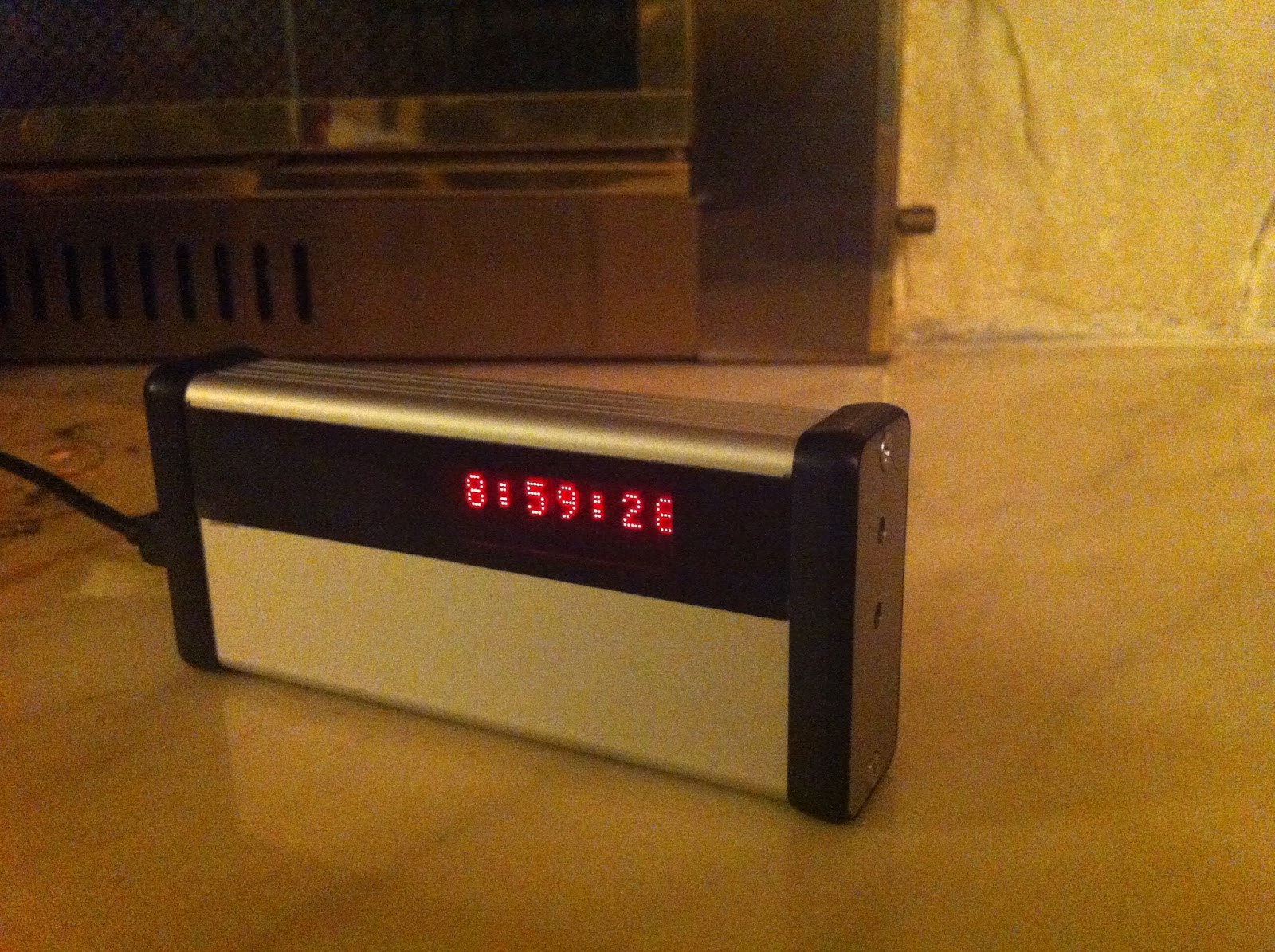
Alex managed to port the Wise Clock 4 code to Arduino Mega2560 (shared here, thanks Alex!). He made this video demonstrating it in action:


Today I have a great day! I did it! I soldered a development board for my Mega2560. A little corrected code and ... voila!  Wiring diagram:
  • rtc sqw (1hz) - pin 2
  • menu key - pin 3
  • set key - pin 4
  • plus key - pin 5
  • speaker - pin 6
  • speaker - pin 7
  • HT1632_WRCLK - pin 10
  • HT1632_CS - pin 11
  • HT1632_DATA - pin 12
  • HT1632_CLK - pin 13
  • rtc sda - pin 20
  • rtc scl - pin 21
(SD While not tested, but I think it works)
  • sd miso - pin 50
  • sd mosi - pin 51
  • sd sck - pin 52
  • sd cs - pin 53

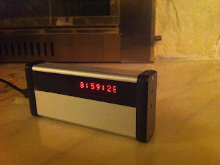
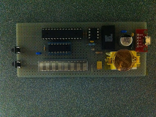
Nelson built his own hand-wired version of WiFiChron and it looks awesome:
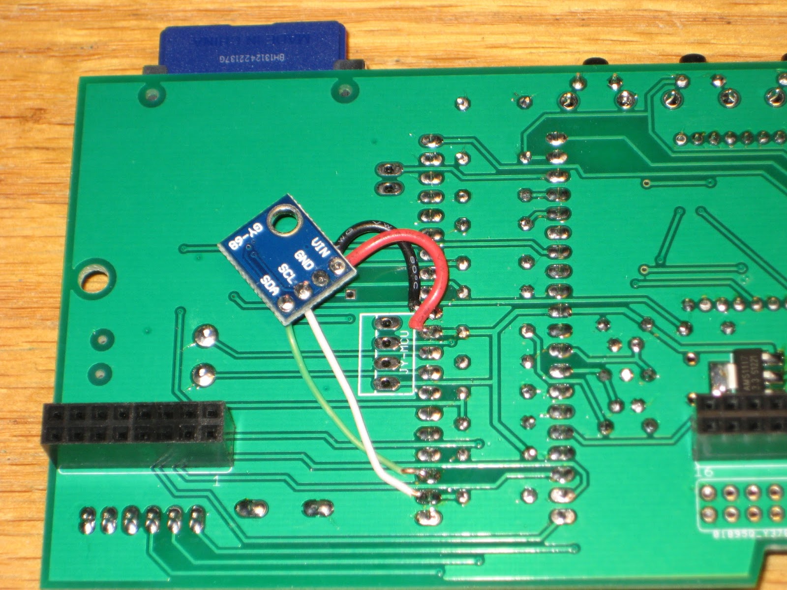
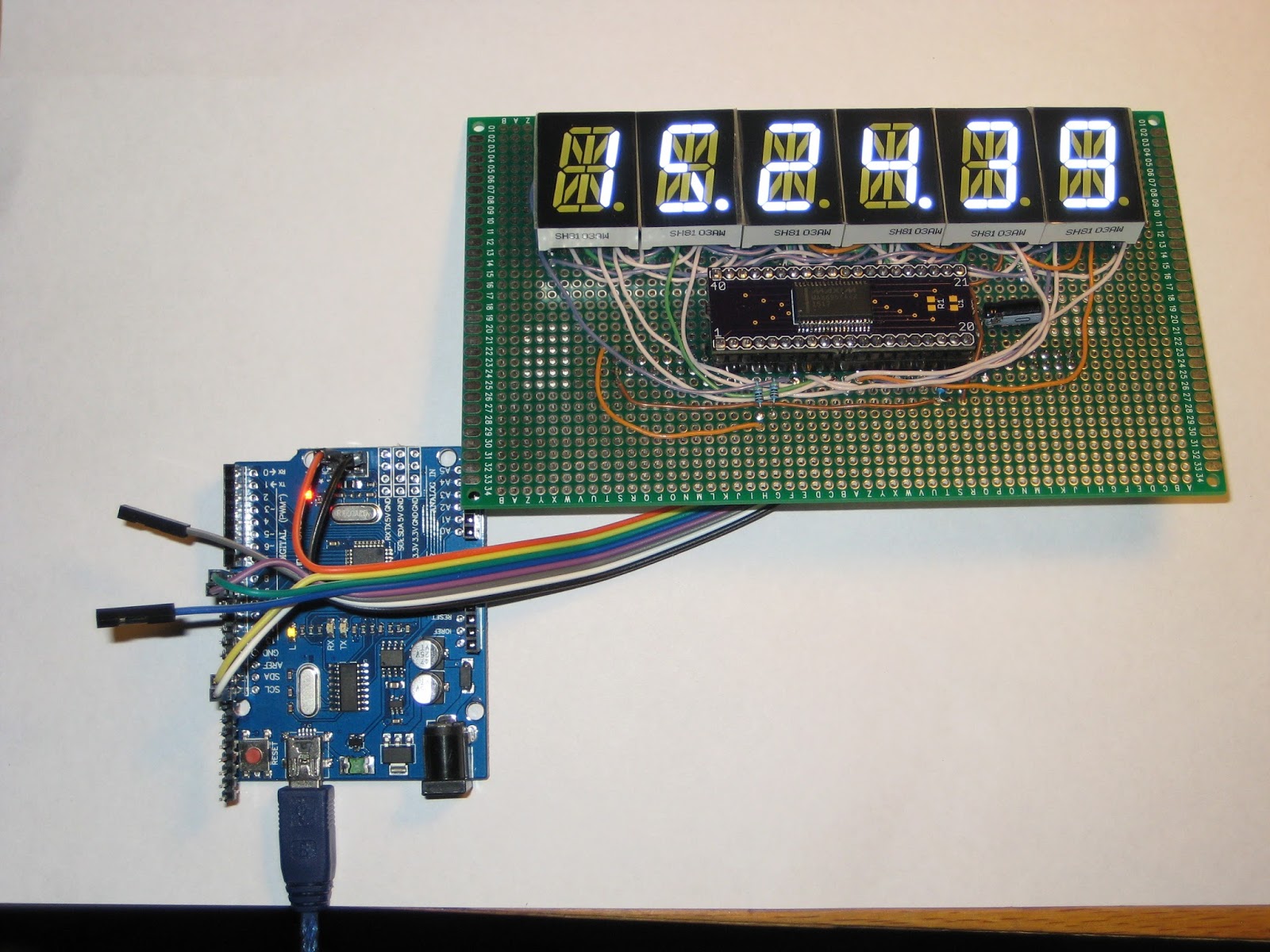


MikeM sent in (thanks Mike!) his latest WiFiChron code (available here).
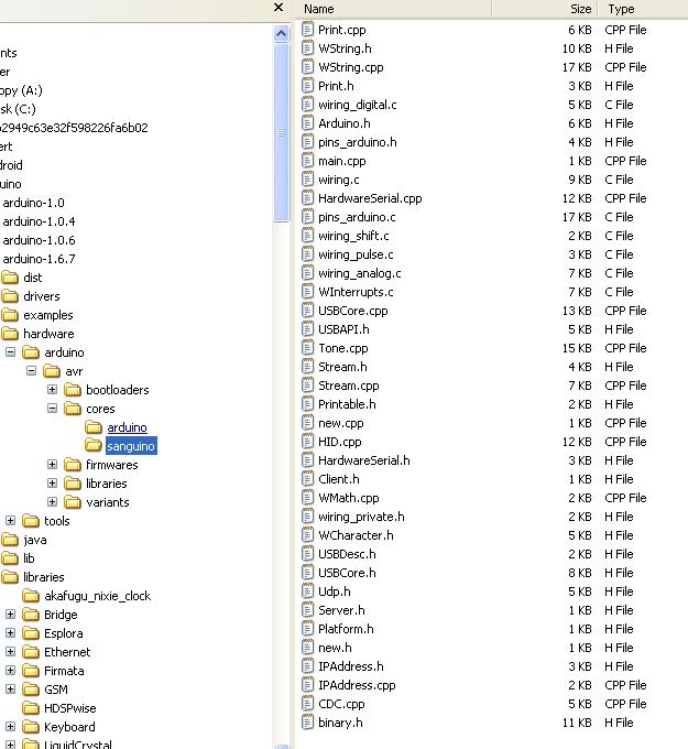
The enclosed zip file compiles under Arduino 1.6.8, though it generates a warning I haven't figured out how to eliminate.
Ray ran into a problem with data overruns. When data in an RSS feed was split between multiple packets, sometimes the last few bytes of a packet were dropped from the RSS buffer. I didn't see that problem with my clock when I was developing the code, nor did I see it on the WiseClock4. I've re-built the RSS state machine to be more CPU efficient, and now the packets are processed without drops. We probably don't need to change the RSS code on the WiseClock4 as it runs at 16 MHz and not 8 MHz like the WiFiChron.
I also changed the PROGMEM statements to fit the 1.6.8 standard.
And finally, I got the PCBs for the 1284-equipped versions of WiFiChron and bGeigie nano.
For both I relied on internal (software-driven) pull-ups (basically I eliminated the pull-up resistors), without checking first if that would work. Unfortunately, the current sanguino library does not implement correctly the function pinMode(x, INPUT_PULLUP). So I had to resort to resistors solder on the back of the board. That, plus missing a (necessary) decoupling capacitor, plus also missing some connections on the bGeigie board, made for a "fun-filled", but in the end successful, testing. More on these in a future post.

Wise Clock 4 software for Arduino 1.6.8

Scott H. put the time and the effort to port the Wise Clock 4 code (also the HDSP and WiFiChron code) to Arduino 1.6.8 (the latest, but maybe not the greatest). This is a big endeavor, which I did not plan to pursue any time soon. Now, thanks to Scott, here we have it. I compiled it and uploaded it myself, on Windows (he did it on Mac).
But before uploading to ATmega1284, this section needs to be inserted in boards.txt (*):

##############################################
atmega1284.name=Sanguino W/ ATmega1284p 16mhz
atmega1284.upload.tool=avrdude
atmega1284.upload.protocol=stk500v1
atmega1284.upload.maximum_size=129024
atmega1284.upload.speed=57600
atmega1284.bootloader.low_fuses=0xFF
atmega1284.bootloader.high_fuses=0x98
atmega1284.bootloader.extended_fuses=0xFD
atmega1284.bootloader.path=atmega
atmega1284.bootloader.file=atmega1284p_16MHz.hex
atmega1284.bootloader.unlock_bits=0x3F
atmega1284.bootloader.lock_bits=0x0F
atmega1284.build.mcu=atmega1284p
atmega1284.build.f_cpu=16000000L
atmega1284.build.core=sanguino
atmega1284.build.board=AVR_ATMEGA1284
##############################################

Note the 2 new (compared to previous versions of boards.txt) required lines, "upload.tool" and "build.board" (which has a default value though).

Next, as specified in the line "atmega1284.build.core=sanguino", we need to create the folder "sanguino", containing the core files. Folder structure should look like this:


Note that a few sanguino core files that worked in Arduino 1.0.6 require changes. Like the Wise Clock 4 files, most of these code changes are related to the PROGMEM definition, which now requires every progmem variable to be constant. The modified files are WString.* and Print.*, copies of the arduino core files.

(*) There is a more "user friendly" way to add a new board, that involves downloading packages from a specified URL, but I found the learning curve for this method too steep (or, to say it differently, I was too lazy).

Go Behind the Scenes of Installing an Interactive LED Art Exhibit

Nick Squires details his time spent using his maker skills to produce an interactive art installation and performance.

Read more on MAKE

The post Go Behind the Scenes of Installing an Interactive LED Art Exhibit appeared first on Make: DIY Projects and Ideas for Makers.

Add a barometer sensor to Wise Clock 4

While cleaning up my desk, I found a little I2C module that I completely forgot about. It is a breakout for BMP180 barometer sensor, which I probably bought on ebay for a couple of dollars (I just checked, it is still under $2). This tiny board can be added literally to any Arduino clock to display atmospheric pressure, with the help of Adafruit_BMP085 library.

Connecting the barometer to Wise Clock 4 is trivial: I soldered wires directly to processor pins (SDA, SCL, VCC and GND), as shown in the photo. There is plenty of clearance between the board and the display.


In the software, as mentioned, I used the Adafruit BMP085 library, which also covers the compatible BMP180. There is no extra setting required from the user: the pressure is displayed together with the temperature, and enabled/disabled from the TEMP+/- menus. Also, there is no extra settings when compiling/building: if the BMP180 module is not installed, no pressure data will be displayed.

Essentially, the new code consists of 2 functions added to the AppTmp class:

boolean CAppTmp::initBarometer()
{
  bmp = new Adafruit_BMP085_Unified(10085);
  isBaro = bmp->begin();
}

int CAppTmp::getPressure()
{
  int pressure = 0;
  if (isBaro)
  {
sensors_event_t event;
bmp->getEvent(&event);
    if (event.pressure)
{
  pressure = event.pressure;
}
  }
  return pressure;
}      

Another nice thing about BMP180 is that it can also provide the temperature. But, like DS3231, it seems to be a little off compared with a regular thermometer sitting nearby.

Next, I will try to attached the little barometer to wsduino in an aesthetically pleasing manner, probably in the empty space in the top left corner.

You Can Build Arduino multi-device Networks with Temboo

Is there a cool Internet of Things idea that you’ve wanted to try out with your Arduino, but just haven’t had time for?  Building a network that integrates multiple sensors and boards into one cohesive application can be time-consuming and difficult.  To make it a bit easier, Temboo just introduced new Machine-to-Machine programming that lets you connect Arduino and Genuino boards running locally in a multi-device network to the Internet.  Now, you can bring all the power and flexibility of Internet connectivity to Arduino applications without giving up the benefits of using low power, local devices.

Our friends at Temboo now support three M2M communication protocols for Arduino boards: MQTT, CoAP, and HTTP. You can choose which to use based on the needs of your application and, once you’ve made your choice, automatically generate all the code you need to connect your Arduinos to any web service. You can also save the network configurations that you specify, making it easy to add and subtract devices or update their behavior remotely.

With Temboo M2M, you can program flexible distributed device applications in minutes. From monitoring air quality and noise levels in cities to controlling water usage in agricultural settings, networked sensors and devices enable all sorts of powerful IoT applications. You can see it all in action in the video below, which shows how they built an M2M network that monitors and controls different machines working together on a production line.

Arduino Blog 15 Dec 17:02

The next steps of the Arduino Create Betatesting

A few months have passed from the launch of the internal betatesting of Arduino Create. We are finally ready to open up the number of people who can use and experiment with this online platform. Today each betatester currently in the program has received 5 invites to get other Arduino tinkerers on board, we have also added about 100 people who tried the platform during Maker Faires and other events, or expressed interest online.

Most importantly we have a public waiting list for anyone who wants to try Arduino Create before hand and give us feedback.
You can SIGN UP herethe first 100 people will receive an invite right away, we will add the other subscribers as the betatesting unfolds.

What’s new?

The Arduino Create Editor has most of the Arduino Desktop IDE features, it is a fully functional Editor, and you can start developing your projects on it right away. We are really close on having everything delivered in HTTPS, we are working hard to add the Library Manager and support for all the Certified and AtHeart boards. Next in our roadmap is including a Sharing feature and a Chrome OS plugin.
As already said in the past, we are always going to provide our community with a offline solution, so don’t worry

When you use Arduino Create for the first time you will be prompted to install a plugin (agent). While your Sketchbook and the apps are hosted in the Cloud, the plugin will locally check the USB ports on your computer. The plugin detects if any board has been connected, if you are uploading a sketch, or you are using the Serial Monitor. The Arduino Create agent is open-source, and available for Mac, Windows and Linux! If you find it interesting you can contribute to it or fork it to use it in your projects.

We are currently working on a brand-new tutorial platform, Arduino Create Projects, in collaboration with Hackster.io. We are planning to release it at the beginning of 2016. Arduino users will finally have a place where they can share their own projects and include step by step guides, schematics and layout references, pictures, videos, the code they wrote, and useful links and comments. We can’t wait to share it with you all so stay tuned!


Arduino Software Update Introduces Command-Line Tool, Serial Data Plotter

Arduino releases version 1.6.6 of their IDE software, adding new tools and features for programming Arduino-compatible microcontrollers.

Read more on MAKE

The post Arduino Software Update Introduces Command-Line Tool, Serial Data Plotter appeared first on Make: DIY Projects, How-Tos, Electronics, Crafts and Ideas for Makers.

Keeping the Arduino website in motion

We never rest, even during summer, to serve our community and we announce today that we’ve refreshed over 150 example pages and redesigned the Examples area, offering an updated support to the current Arduino Software (IDE) Built-in and Libraries examples

Our website is a living entity that everyday hosts a huge number of visitors. They are looking for software, information, guidelines, ideas and also the right tutorial to start tinkering with their new board on a specific issue or project.

The Reference is the place where everything is documented and explained, with dry and essential information that is also included locally with every Arduino Software (IDE) installation.

Our software also includes a number of built-in sketches that help our users to quickly understand how the various functions and libraries may be used and applied to specific projects and tasks. We all started with the famous Blink and at the end of this tutorial we all felt the power and the excitement of having tamed our board with the upload of our first sketch. Keeping all these examples in good shape and updated is essential to keep you users safe from troubles or difficulties.

These examples evolve, as the libraries also evolve, therefore the sketches may be updated, amended or added. Each of these examples is commented and has an introductory part that gives a description of the purpose of the sketch and – if necessary – the instructions to put together the circuit. We know that the information provided inside the IDE and the sketches is not enough and therefore we made an area of our website where each sketch is explained and documented.

Year after year, board after board and library after library, many “hands” contributed to this area, filling gaps and amending things to reflect the Arduino Software (IDE) status. It has been an ongoing process that inevitably brought the Tutorials area in a state where many styles and ways of explaining things merged. We have big plans for our www.arduino.cc website and it is important to clean and fix the existing areas before we add new contents. This is why my first task – as editorial manager – has been the refresh and overall alignment of our Examples and Examples from Libraries pages.

We have roughly 150 pages documenting our Examples for the current products and libraries and going through them all wasn’t exactly a piece of cake: many things were checked for each example and sometimes things were outdated or missing. We also have our sister brand Genuino that got its space in all the relevant example pages. Now contents, style, look and feel and links in this area are ready for new and fresh developments.

I would like to end this post adding that this task was also a very good opportunity to refresh my knowledge about the powerful capabilities of Arduino programming language and its libraries. I had a few doubts on how to do a few things in my own sketches and going through all the examples gave me the hints I was missing.

The plain list of examples available in the Arduino Software (IDE) is just made of the sketch names, conversely in our pages you find a brief description of each of them. I suggest that you wander through these descriptions: let them excite your curiosity and inspire you!

Arduino Blog 11 Sep 10:00

Experimenting with MAX6955

MAX6955 is an interesting LED driver chip. It is the primordial charlieplexing device, being the materialization of a technique invented by Charlie Allen of Maxim Integrated. Without understanding how charelieplexing works, it is actually counter-intuitive to wire multiple (up to 8) 16-segment displays to such a driver chip. Fortunately, Maxim has great documentation on how to do it.


My experimenting actually started with MAX6954. After many failed tries due to SPI issues (Maxim uses a special interpretation of the protocol, I read), I switched to MAX6955.

MAX6955 is the I2C sibling of MAX6954 (which uses SPI). They both have identical LED driving abilities, only the microcontroller interface part of the chips differ. Once, both chips were available in DIP-40 package. Now, MAX6955 only comes in SSOP-36 (MAX6954 is still available in DIP-40). Luckily, the pin configurations for the two chips are compatible, which allows for easy swap. For this reason, I designed a breakout board (shared at oshpark), so I can use the same setup I built for MAX6954.


Beside Maxim's, there isn't much documentation on how to control these chips. One of the reasons they are rarely used by hobbyists is probably their price (about $20 at digikey), although in the same range as the wildly popular MAX72xx LED driver (available at around $10 from digikey). In "reality", for some reason, MAX72xx could be had for $1 or less on ebay, unlike MAX6954/6955. Therefore, a hobby kit designed around MAX6955 would be "extremely" expensive compared with others using different LED driving chips (e.g. MAX72xx).

MAX6954/6955 was designed to drive common cathode LED displays, like MAX72xx. But unlike MAX72xx, it cannot be used for displays with common segments (which require multiplexing), like the ones below (and used here). MAX6954/6955 requires the 14/16-segment displays to be single digit/character, because not all segments will be wired together.


Below is the Arduino sketch I wrote that works very well with MAX6955. Although it uses a minimal set of commands, it is capable of displaying a character at a given position, light up the dot, and even scroll a long message.

#include "Wire.h"

#define ID_MAX6955 B1100000 
#define NUM_DISPLAYS 6

#define max6955_reg_decodeMode      0x01
#define max6955_reg_globalIntensity 0x02
#define max6955_reg_scanLimit       0x03
#define max6955_reg_configuration   0x04
#define max6955_reg_displayTest     0x07
#define max6955_reg_digitType       0x0C

int writeMAX6955(char command, char data)
{
    Wire.beginTransmission(ID_MAX6955);
    Wire.write(command);
    Wire.write(data);
    Wire.endTransmission();
}

void initMAX6955()
{
    Wire.begin();
    // ascii decoding for all digits;
    writeMAX6955(max6955_reg_decodeMode, 0xFF);
    // brightness: 0x00 =  1/16 (min on)  2.5 mA/seg;
    // 0x0F = 15/16 (max on) 37.5 mA/segment
    writeMAX6955(max6955_reg_globalIntensity, 0x07);
    // active displays: 0x07 -> all;
    writeMAX6955(max6955_reg_scanLimit, 0x07);
    // set normal operation;
    writeMAX6955(max6955_reg_configuration, 0x01);
    // segments/display: 0xFF=14-seg; 0=16 or 7-seg;
    writeMAX6955(max6955_reg_digitType, 0x00);
    // display test off;
    writeMAX6955(max6955_reg_displayTest, 0x00);
}

void setup()
{
  // set D8 and D9 to GND (for I2C address);
  pinMode(8, OUTPUT);
  pinMode(9, OUTPUT);
  digitalWrite(8, LOW);
  digitalWrite(9, LOW);

  initMAX6955();
  delay(100);
  clear();
//  writeDisplay("HI");
//  writeChar(0, 'A', true);
//  scrollDisplay("     HELLO WORLD", 300);
  writeTime(15, 24, 39);
}

void loop()
{
}

void writeDisplay(char* msg)
{
  for (byte i=0; i < NUM_DISPLAYS; i++)
  {
    if (i < strlen(msg))
      writeMAX6955(0x25-i, msg[i]);
    else
      writeMAX6955(0x25-i, ' ');
  }
}

void writeChar(byte pos, char letter, boolean dotLit)
{
  writeMAX6955(0x25-pos, (dotLit? 0x80 : 0) | letter);
}

void clear()
{
  for (byte i=0; i < NUM_DISPLAYS; i++)
    writeMAX6955(0x25-i, ' ');
}

void scrollDisplay(char* msg, int delayMs)
{
  for (int i=0; i<=strlen(msg); i++)
  {
    writeDisplay(msg+i);
    delay(delayMs);
  }
}

void writeTime(int hours, int minutes, int seconds)
{
  char h1 = (hours/10)? '0' + hours/10 : ' ';
  writeChar(0, h1, false);
  char h2 = '0' + (hours%10);
  writeChar(1, h2, true);
  char m1 = '0' + (minutes/10);
  writeChar(2, m1, false);
  char m2 = '0' + (minutes%10);
  writeChar(3, m2, true);
  char s1 = '0' + (seconds/10);
  writeChar(4, s1, false);
  char s2 = '0' + (seconds%10);
  writeChar(5, s2, false);
}

The I2C address of B1100000 was set by grounding AD0 and AD1 (see table 5 in the datasheet on how to change that address). In my setup, these 2 pins are connected to D8 and D9. Don't forget to pull-up SDA and SCL with 4k7-10k resistors.

The left-most digit is at position 0, accessible at address 0x25. "Digit 1" is the second from left, accessible at address 0x24, and so on. This is determined by the wiring. In my case, "CC0" (in the table 1 of this application note) represents the right-most display, and it is accessible at address 0x20.

Prototype 14-segment-display shield

There are many ways (*) to drive the 6-digit 14-segment common cathode display from Seeed Studio.
This time I chose to multiplex two MAX7221, a method described here (but used to drive a bi-color 8x8 LED matrix).


The code is based on LedControl library, which I extended to cover the definition and display of 14-segment characters (digits, upper case letters, and a few specials). Below is a relevant fragment of the code I added:

/*
* Segment names in the 14-segment (plus DP) display:
*
*     -     A
*   |\|/|   F,I,J,K,B
*    - -    G,H
*   |/|\|   E,N,M,L,C
*     -  .  D,P
*/
// my wiring:
//            GFEDCBAx
// 1st byte: B11111111
//
//            NHJIKMLP
// 2nd byte: B11111111

const static byte charTable14Seg[43][2] = {
    {B01111110,B10001000},  // 0
    {B00001100,B00001000},  // 1
    {B10110110,B01000000},  // 2
    {B00011110,B01000000},  // 3
    {B11001100,B01000000},  // 4
    {B11010010,B00000010},  // 5
    {B11111010,B01000000},  // 6
    {B00000010,B00001100},  // 7
    {B11111110,B01000000},  // 8
    {B11011110,B01000000},  // 9
    {B00000000,B01000000},  // :
    {B00000000,B01000000},  // ;
    {B00000000,B01000000},  // <
    {B00000000,B01000000},  // =
    {B00000000,B01000000},  // >
    {B00000000,B01000000},  // ?
    {B00000000,B01000000},  // @
    {B11101110,B01000000},  // A
    {B00011110,B01100100},  // B
    {B01110010,B00000000},  // C
    {B00011110,B00100100},  // D
    {B11110010,B01000000},  // E
    {B11100010,B01000000},  // F
    {B01111010,B01000000},  // G
    {B11101100,B01000000},  // H
    {B00000000,B00100100},  // I
    {B00111100,B00000000},  // J
    {B11100000,B00001010},  // K
    {B01110000,B00000000},  // L
    {B01101100,B00011000},  // M
    {B01101100,B000100L0},  // N
    {B01111110,B00000000},  // 0
    {B11100110,B01000000},  // P
    {B01111110,B00000010},  // Q
    {B11100110,B01000010},  // R
    {B11011010,B01000000},  // S
    {B00000010,B00100100},  // T
    {B01111100,B00000000},  // U
    {B01100000,B10001000},  // V
    {B01101100,B10000010},  // W
    {B00000000,B10011010},  // X
    {B00000000,B00011100},  // Y
    {B00010010,B10001000},  // Z
};
...
void setChar14Seg(byte pos, byte ascii)
{
  if (pos>7)
    return;

  if (ascii>90 || ascii<48)
    return;

  byte index = ascii - 48;
  for(byte seg=0; seg < 8; seg++)
  {
    SetLed(SEG_AG, pos, seg, charTable14Seg[index][0] & 1 << seg);
    SetLed(SEG_GN, pos, seg, charTable14Seg[index][1] & 1 << seg);
  }
}

This method (hardware and software) can be used for up to 8 14/16-segment displays.


(*) Should be the topic of a future post.