Posts with «shield» label

The Arduino Yun Shield

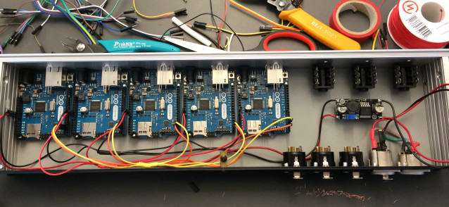
A few years ago, the most common method to put an Arduino project on the web was to add a small router loaded up with OpenWrt, wire up a serial connection, and use this router as a bridge to the Internet. This odd arrangement was possibly because the existing Arduino Ethernet and WiFi shields were too expensive or not capable enough, but either way the Arduino crew took notice and released the Arduino Yun: an Arduino with an SoC running Linux with an Ethernet port. It’s pretty much the same thing as an Arduino wired up to a router, with the added bonus of having tons of libraries available.

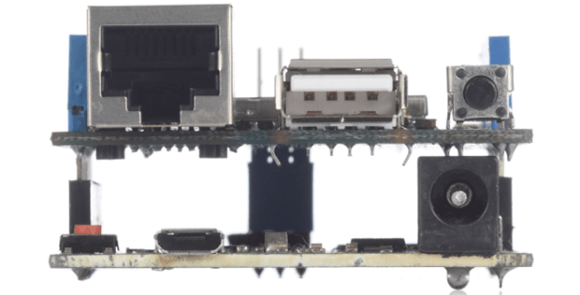
Since the Yun is basically a SoC grafted onto an Arduino, we’re surprised we haven’t seen something like this before. It’s an Arduino shield that adds a Linux SoC, WiFi, Ethernet, and USB Host to any Arduino board from the Uno, to the Duemilanove and Mega. It is basically identical to the Arduino Yun, and like the Yun it’s completely open for anyone to remix, share, and reuse.

The Yun shield found on the Dragino website features a small SoC running OpenWrt, separated from the rest of the Arduino board with a serial connection. The Linux side of the stack features a 400MHz AR9331 (the same processor as the Yun), 16 MB of Flash, and 64 MB of RAM for running a built-in web server and sending all the sensor data an Arduino can gather up to the cloud (Yun, by the way, means cloud).

All the hardware files are available on the Yun shield repo, with the Dragino HE module being the most difficult part to source.


Filed under: Arduino Hacks, hardware

Two new little tools for your tinkering time with Arduino

Two new Arduino products are available starting today from the Arduino Store. Read below for details!

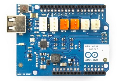
Arduino USB Host Shield

This shield allows you to connect devices to your Arduino using a USB port, for example game controllers, digital cameras, phones, keyboards, etc:

- it is based on the MAX3421E, which is a USB peripheral/host controller containing the digital logic and analog circuitry necessary to implement a full-speed USB peripheral or a full-/low-speed host compliant to USB specification rev 2.0.

- it can be used with the “USB Host Library for Arduino” hosted by Lauzus from circuits@home on GitHub (click to download zip).

If you want to see how to use it, take a look at this tutorial from Officine Arduino which used it to add wireless to an RC Car.

Buy USB Host Shield now


——————————-

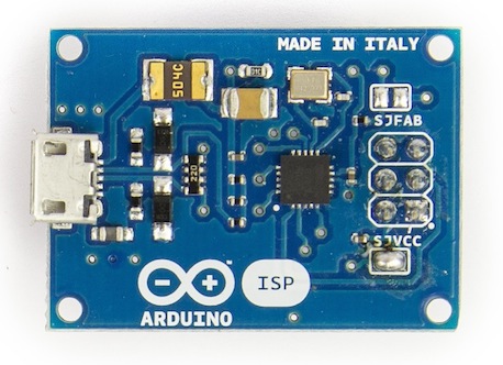
ArduinoISP

It’s a tiny AVR-ISP (in-system programmer) based on David Mellis’ project FabISP and useful to anyone needing more space on the Arduino board. Uploading a sketch with an external programmer can be used for three main reasons:

- remove the bootloader and use the extra space for your sketch

- burn the bootloader on your Arduino, so you can recover it if you accidentally corrupt the bootloader.

- when you use a new ATmega microcontroller in your Arduino, and you need the bootloader in order to upload a sketch in the usual way.

For more details about using the Arduino ISP please visit the Getting Started page

Learn how to program an ATtiny and to read your Arduino built-in EEPROM using ArduinoISP in the tutorials on Scuola.

Buy Arduino ISP now


New Project: DIY Arduino Bluetooth Programming Shield

Upload sketches to your Arduino wirelessly with a DIY Arduino Bluetooth Programming Shield.

Read more on MAKE

Easily test and experiment with GSM modules using AT Command Tester

Introduction

Working with GSM modules and by extension Arduino GSM shields can either be a lot of fun or bring on a migraine. This is usually due to the quality of module, conditions placed on the end user by the network, reception, power supply and more.

Furthermore we have learned after several years that even after following our detailed and tested tutorials, people are having trouble understanding why their GSM shield isn’t behaving. With this in mind we’re very happy to have learned about a free online tool that can be used to test almost every parameter of a GSM module with ease – AT Command Tester. This software is a Java application that runs in a web browser, and communicates with a GSM module via an available serial port.

Initial Setup

It’s simple, just visit http://m2msupport.net/m2msupport/module-tester/ with any web browser that can run Java. You may need to alter the Java security settings down to medium. Windows users can find this in Control Panel> All Control Panel Items  > Java – for example:

Once the security settings have been changed, just visit the URL, click ‘accept’ and ‘run’ in the next dialogue box that will appear, for example:

And after a moment, the software will appear:

Once you’re able to run the AT Command Tester software, the next step is to physically connect the hardware. If you’re just using a bare GSM module, a USB-serial adaptor can be used for easy connection to the PC. For Arduino GSM shield users, you can use the Arduino as a bridge between the shield and PC, however if your GSM shield uses pins other than D0/D1 for serial data transmission (such as our SIM900 shield) then you’ll need to upload a small sketch to bridge the software and hardware serial ports, for example:

//Serial Relay – Arduino will patch a serial link between the computer and the GPRS Shield
//at 19200 bps 8-N-1 Computer is connected to Hardware UART
//GPRS Shield is connected to the Software UART

#include <SoftwareSerial.h>

SoftwareSerial mySerial(7,8); // change these paramters depending on your Arduino GSM Shield

void setup()
{
  Serial.begin(19200);
  //Serial.println(“Begin”);
  mySerial.begin(19200);

}

void loop()
{
  if (mySerial.available())
    Serial.write(mySerial.read());
  if (Serial.available())
    mySerial.write(Serial.read());
}

Using the software

Once you have the hardware connected and the Arduino running the required sketch, run the software – then click “Find ports” to select the requried COM: port, set the correct data speed and click “Connect”. After a moment the software will interrogate the GSM module and report its findings in the yellow log area:

 As you can see on the left of the image above, there is a plethora of options and functions you can run on the module. By selecting the manufacturer of your GSM module form the list, a more appropriate set of functions for your module is displayed.

When you click a function, the AT command sent to the module and its response is shown in the log window – and thus the magic of this software. You can simply throw any command at the module and await the response, much easier than looking up the commands and fighting with terminal software. You can also send AT commands in batches, experiment with GPRS data, FTP, and the GPS if your module has one.

To give you a quick overview of what is possible, we’ve made this video which captures us running a few commands on a SIM900-based Arduino shield. If possible, view it in 720p.

Conclusion

Kudos to the people from the M2Msupport website for bringing us this great (and free) tool. It works – so we’re happy to recommend it. And if you enjoyed this article, or want to introduce someone else to the interesting world of Arduino – check out my book (now in a third printing!) “Arduino Workshop”.

Have fun and keep checking into tronixstuff.com. Why not follow things on twitterGoogle+, subscribe  for email updates or RSS using the links on the right-hand column, or join our forum – dedicated to the projects and related items on this website. Sign up – it’s free, helpful to each other –  and we can all learn something.

The post Easily test and experiment with GSM modules using AT Command Tester appeared first on tronixstuff.

Easily test and experiment with GSM modules using AT Command Tester

Introduction

Working with GSM modules and by extension Arduino GSM shields can either be a lot of fun or bring on a migraine. This is usually due to the quality of module, conditions placed on the end user by the network, reception, power supply and more.

Furthermore we have learned after several years that even after following our detailed and tested tutorials, people are having trouble understanding why their GSM shield isn’t behaving. With this in mind we’re very happy to have learned about a free online tool that can be used to test almost every parameter of a GSM module with ease – AT Command Tester. This software is a Java application that runs in a web browser, and communicates with a GSM module via an available serial port.

Initial Setup

It’s simple, just visit http://m2msupport.net/m2msupport/module-tester/ with any web browser that can run Java. You may need to alter the Java security settings down to medium. Windows users can find this in Control Panel> All Control Panel Items  > Java – for example:

Once the security settings have been changed, just visit the URL, click ‘accept’ and ‘run’ in the next dialogue box that will appear, for example:

And after a moment, the software will appear:

Once you’re able to run the AT Command Tester software, the next step is to physically connect the hardware. If you’re just using a bare GSM module, a USB-serial adaptor can be used for easy connection to the PC. For Arduino GSM shield users, you can use the Arduino as a bridge between the shield and PC, however if your GSM shield uses pins other than D0/D1 for serial data transmission (such as our SIM900 shield) then you’ll need to upload a small sketch to bridge the software and hardware serial ports, for example:

//Serial Relay – Arduino will patch a serial link between the computer and the GPRS Shield
//at 19200 bps 8-N-1 Computer is connected to Hardware UART
//GPRS Shield is connected to the Software UART

#include <SoftwareSerial.h>

SoftwareSerial mySerial(7,8); // change these paramters depending on your Arduino GSM Shield

void setup()
{
  Serial.begin(19200);
  //Serial.println(“Begin”);
  mySerial.begin(19200);

}

void loop()
{
  if (mySerial.available())
    Serial.write(mySerial.read());
  if (Serial.available())
    mySerial.write(Serial.read());
}

Using the software

Once you have the hardware connected and the Arduino running the required sketch, run the software – then click “Find ports” to select the requried COM: port, set the correct data speed and click “Connect”. After a moment the software will interrogate the GSM module and report its findings in the yellow log area:

 As you can see on the left of the image above, there is a plethora of options and functions you can run on the module. By selecting the manufacturer of your GSM module form the list, a more appropriate set of functions for your module is displayed.

When you click a function, the AT command sent to the module and its response is shown in the log window – and thus the magic of this software. You can simply throw any command at the module and await the response, much easier than looking up the commands and fighting with terminal software. You can also send AT commands in batches, experiment with GPRS data, FTP, and the GPS if your module has one.

To give you a quick overview of what is possible, we’ve made this video which captures us running a few commands on a SIM900-based Arduino shield. If possible, view it in 720p.

Conclusion

Kudos to the people from the M2Msupport website for bringing us this great (and free) tool. It works – so we’re happy to recommend it. And if you enjoyed this article, or want to introduce someone else to the interesting world of Arduino – check out my book (now in a third printing!) “Arduino Workshop”.

Have fun and keep checking into tronixstuff.com. Why not follow things on twitterGoogle+, subscribe  for email updates or RSS using the links on the right-hand column, or join our forum – dedicated to the projects and related items on this website. Sign up – it’s free, helpful to each other –  and we can all learn something.

Tutorial – Arduino Mega and SM5100B GSM Cellular

Connect your Arduino Mega or compatible to the cellular network with the SM5100 GSM module shield from Tronixlabs. If you have an Arduino Uno or compatible, visit this page. If you are looking for tutorials using the SIMCOM SIM900 GSM module, click here.

This is chapter twenty-seven of a series originally titled “Getting Started/Moving Forward with Arduino!” by John Boxall – A tutorial on the Arduino universe. The first chapter is here, the complete series is detailed here.

Updated 18/01/2014

Introduction

The purpose of this tutorial is to have your Arduino Mega to communicate over a GSM mobile telephone network using a shield based on the SM5100B module from Tronixlabs. We’ve written this as the shield from Sparkfun used in the previous tutorial was somewhat fiddly for use with an Arduino Mega – so this shield is a more convenient alternative:

Our goal is to illustrate various methods of interaction between an Arduino Mega and the GSM cellular network using the shield shown above, with which you can then use your existing knowledge to build upon those methods. Doing so isn’t easy – but it isn’t that difficult.

Stop! Please read first:

  • It is assumed that you have a solid understanding of how to program your Arduino. If not, start from chapter zero
  • Sending SMS messages and making phone calls cost real money, so it would be very wise to use a prepaid cellular account or one  that allows a fair amount of calls/SMS
  • The GSM shield only works with “2G” GSM mobile networks operating on the 850, 900 and PCS1800 MHz frequencies. If in doubt, ask your carrier first
  • Australians – you can use any carrier’s SIM card
  • Canadians – this doesn’t work with Sasktel
  • North Americans – check with your cellular carrier first if you can use third-party hardware (i.e. the shield)
  • I cannot offer design advice for your project nor technical support for this article.
  • If you are working on a college/university project and need specific help – talk to your tutors or academic staff. They get paid to help you.
  • Please don’t make an auto-dialler…


Getting started

Before moving forward there us one vital point you need to understand – the power supply. The GSM shield can often require up to 2A of current in short bursts – especially when turned on, reset, or initiating a call.

However your Arduino board can only supply just under 1A. It is highly recommended that you use an external regulated power supply of between 9 and 12 VDC capable of delivering 2A of current – from an AC adaptor, large battery with power regulator, etc. Otherwise there is a very strong probability of damaging your shield and Arduino. When connecting this supply use the Vin and GND pins. Do not under any circumstances power the Arduino and shield from just the USB power.

Next – use an antenna! The wire hanging from the shield is not an antenna. YOU NEED THE ANTENNA! For example:

Furthermore, care needs to be taken with your GSM shield with regards to the aerial lead-module connection, it is very fragile:

Pressing the hardware reset button on the shield doesn’t reset the GSM module – you need to remove the power for a second. And finally, download this document (.pdf). It contains all the AT and ERROR codes that will turn up when you least expect it. Please review it if you are presented with a code you are unsure about.

Wow – all those rules and warnings?

The sections above may sound a little authoritarian, however I want your project to be a success. With the previous iterations of the tutorial people just didn’t follow the instructions – so we hope you do.

Initial check – does it work?

This may sound like a silly question, but considering the cost of the shield and the variables involved, it is a good idea to check if your setup is functioning correctly before moving on. From a hardware perspective for this article, you will need your Arduino board, the GSM shield with activated SIM card and an aerial, and the power supply connected.

Next you need to set the serial line jumpers. These determine which of the four hardware serial ports we use to communicate with the GSM module. Place a jumper over each of the RX1 and TX1 pairs as shown in the following image. By doing this the communication with the GSM module is via Serial1 in our sketches, leaving Serial for normal communications such as the serial monitor.

Make sure your SIM card is set to not require a PIN when the phone is turned on. You can check and turn this requirement off with your cellphone. 

For our initial test, upload the following sketch:

// Example 27.1

char incoming_char=0;      // Will hold the incoming character from the Serial Port.
void setup()
{
  //Initialize serial ports for communication.
  Serial.begin(9600);
  Serial1.begin(9600);
  Serial.println("Starting SM5100B Communication...");
}
void loop()
{
  //If a character comes in from the cellular module...
  if(Serial1.available() >0)
  {
    incoming_char=Serial1.read();    // Get the character from the cellular serial port.
    Serial.print(incoming_char);  // Print the incoming character to the terminal.
  }
  //If a character is coming from the terminal to the Arduino...
  if(Serial.available() >0)
  {
    incoming_char=Serial.read();  // Get the character coming from the terminal
    Serial1.print(incoming_char);    // Send the character to the cellular module.
  }
}

Then connect the GSM shield, aerial, insert the SIM card and apply power. Open the serial monitor box in the Arduino IDE and you should be presented with the following:

It will take around fifteen to thirty seconds for the text above to appear in full. What you are being presented with is a log of the GSM module’s actions. But what do they all mean?

  • +SIND: 1 means the SIM card has been inserted;
  • the +SIND: 10 line shows the status of the in-module phone book. Nothing to worry about there for us at the moment;
  • +SIND: 11 means the module has registered with the cellular network
  • +SIND: 3 means the module is partially ready to communicate
  • and +SIND: 4 means the module is registered on the network, and ready to communicate

All the SIND data and other codes the module will give you are listed in the AT command guide we suggested you download. Please use it – any comments such as “What’s +SIND:5?” will be deleted.

From this point on, we will need to use a different terminal program, as the Arduino IDE’s serial monitor box isn’t made for full two-way communications. You will need a terminal program that can offer full two-way com port/serial communication. For those running MS Windows, an excellent option is available here.

It’s free, however consider donating for the use of it. For other operating systems, people say this works well. So now let’s try it out with the terminal software. Close your Arduino IDE serial monitor box if still open, then run your terminal, set it to look at the same serial port as the Arduino IDE was. Ensure the settings are 9600, 8, N, 1. Then reset your Arduino and the following should appear:

The next step is to tell the GSM module which network frequency(ies) to use. View page 127 of the AT command document. There is a range of frequency choices that our module can use. If you don’t know which one to use, contact the telephone company that your SIM card came from. Australia – use option 4. Find your option, then enter:

AT+SBAND=x

(where X is the value matching your required frequency) into the terminal software and click SEND. Then press reset on the Arduino and watch the terminal display. You should hopefully be presented with the same text as above, ending with +SIND: 4. If your module returns +SIND: 4, we’re ready to move forward.

If your terminal returned a +SIND: 8 instead of 4, double-check your hardware, power supply, antenna, and the frequency band chosen. If all that checks out call your network provider to see if they’re rejecting the GSM module on their network.

Our next test is to call our shield. So, pick up a phone and call it. Your shield will return data to the terminal window, for example:

As you can see, the module returns what is happening. I let the originating phone “ring” three times, and the module received the caller ID data (sorry, blacked it out). Some telephone subscribers’ accounts don’t send caller ID data, so if you don’t see your number, no problem. “NO CARRIER” occurred when I ended the call. +SIND: 6,1 means the call ended and the SIM is ready.

Have your Arduino “call you”

The document (.pdf) you downloaded earlier contains a list of AT commands – consider this a guide to the language with which we instruct the GSM module to do things. Let’s try out some more commands before completing our initial test. The first one is:

ATDxxxxxx

which dials a telephone number xxxxxx. For example, to call (212)-8675309 use:

ATD2128675309

The next one is:

ATH

which “hangs up” or ends the call. So, let’s reach out and touch someone. In the terminal software, enter your ATDxxxxxxxx command, then hit send. Let your phone ring. Then enter ATH to end the call. If you are experimenting and want to hang up in a hurry, you can also hit reset on the Arduino and it will end the call as well as resetting the system.

So by now you should realise the GSM module is controlled by these AT commands. To use an AT command in a sketch, we use the function:

Serial1.println()

Remember that we used Serial1 as the jumpers on the shield board are set to connect the GSM module to the Serial1 hardware serial port. For example, to dial a phone number, we would use:

Serial1.println("ATD2128675309");

To demonstrate this in a sketch, consider the following simple sketch which dials a telephone number, waits, then hangs up. Replace xxxxxxxx with the number you wish to call:

// Example 27.2

void setup()
{ 
  Serial.begin(9600);
  Serial1.begin(9600);
  delay(10);
  Serial.println("starting delay");
  delay(30000); // give the GSM module time to initialise, locate network etc.
  // this delay time varies. Use example 27.1 sketch to measure the amount
  // of time from board reset to SIND: 4, then add five seconds just in case
}

void loop()
{
  Serial.println("dialling");
  Serial1.println("ATDxxxxxxxxxx"); // dial the phone number xxxxxxxxx
  // change xxxxxxxxxx to your desired phone number (with area code)
  delay(20000); // wait 20 seconds.
  Serial.println("hang up");
  Serial1.println("ATH"); // end call
  do // remove this loop at your peril
  { 
    delay(1); 
  }
  while (1>0);
}

The sketch in example 27.2 assumes that all is well with regards to the GSM module, that is the SIM card is ok, there is reception, etc. The long delay function in void setup() is used to allow time for the module to wake up and get connected to the network. Later on we will read the messages from the GSM module to allow our sketches to deal with errors and so on. However, you can see how we can simply dial a telephone. And here’s a quick video for the non-believers.

Send an SMS from your Arduino

Another popular function is the SMS or short message service, or text messaging. Before moving forward, download and install Meir Michanie’s SerialGSM Arduino library from here. Some of you might be thinking “why are we using a software serial in the following sketch?”. Short answer – it’s just easier.

Sending a text message is incredibly simple – consider the following sketch:

// Example 27.3

#include <SerialGSM.h>
#include <SoftwareSerial.h>
SerialGSM cell(19,18);

void setup()
{ 
  delay(30000); // wait for GSM module
  cell.begin(9600);
}

void sendSMS()
{
  cell.Verbose(true); // used for debugging
  cell.Boot(); 
  cell.FwdSMS2Serial();
  cell.Rcpt("+xxxxxxxxx"); // replace xxxxxxxxx with the recipient's cellular number
  cell.Message("Contents of your text message");
  cell.SendSMS();
}
void loop()
{
  sendSMS();
  do // remove this loop at your peril
  { 
    delay(1); 
  }
  while (1>0);
}

It’s super-simple – just change the phone number to send the text message, and of course the message you want to send. The phone numbers must be in international format, e.g. Australia 0418 123456 is +61418123456 or USA (609) 8675309 is +16098675309. And the results:

Reach out and control something

Now let’s discuss how to make something happen by a simple telephone call. And the best thing is that we don’t need the the GSM module to answer the telephone call (thereby saving money) – just let the module ring a few times. How is this possible? Very easily. Recall Example 27.1 above – we monitored the activity of the GSM module by using our terminal software.

In this case what we need to do is have our Arduino examine the text coming in from the serial output of the GSM module, and look for a particular string of characters.

When we telephone the GSM module from another number, the module returns the text as shown in the image below:

We want to look for the text “RING”, as (obviously) this means that the GSM shield has recognised the ring signal from the exchange. Therefore need our Arduino to count the number of rings for the particular telephone call being made to the module. (Memories – Many years ago we would use public telephones to send messages to each other.

For example, after arriving at a foreign destination we would call home and let the phone ring five times then hang up – which meant we had arrived safely). Finally, once the GSM shield has received a set number of rings, we want the Arduino to do something.

From a software perspective, we need to examine each character as it is returned from the GSM shield. Once an “R” is received, we examine the next character. If it is an “I”, we examine the next character. If it is an “N”, we examine the next character. If it is a “G”, we know an inbound call is being attempted, and one ring has occurred.

We can set the number of rings to wait until out desired function is called. In the following example, when the shield is called, it will call the function doSomething() after three rings.

The function doSomething() controls two LEDs, two red,  two green. Every time the GSM module is called for 3 rings, the Arduino alternately turns on or off the LEDs. Using the following sketch as an example, you now have the ability to turn basically anything on or off, or call your own particular function:

// Example 27.4

char inchar; // Will hold the incoming character from the Serial Port.
int numring=0;
int comring=3; 
int onoff=0; // 0 = off, 1 = on

int led1 = 9;
int led2 = 10;
int led3 = 11;
int led4 = 12;

void setup()
{
  // prepare the digital output pins
  pinMode(led1, OUTPUT);
  pinMode(led2, OUTPUT);
  pinMode(led3, OUTPUT);
  pinMode(led4, OUTPUT);
  digitalWrite(led1, LOW);
  digitalWrite(led2, LOW);
  digitalWrite(led3, LOW);
  digitalWrite(led4, LOW);

  //Initialize GSM module serial port for communication.
  Serial1.begin(9600);
  delay(30000); // give time for GSM module to register on network etc.
}

void doSomething()
{
  if (onoff==0)
  {
    onoff=1;
    digitalWrite(led1, HIGH);
    digitalWrite(led2, HIGH);    
    digitalWrite(led3, LOW);
    digitalWrite(led4, LOW);    

  } 
  else
    if (onoff==1)
    {
      onoff=0;
      digitalWrite(led1, LOW);
      digitalWrite(led2, LOW);    
      digitalWrite(led3, HIGH);
      digitalWrite(led4, HIGH);  
    }
}

void loop() 
{
  //If a character comes in from the cellular module...
  if(Serial1.available() >0)
  {
    inchar=Serial1.read(); 
    if (inchar=='R')
    {
      delay(10);
      inchar=Serial1.read(); 
      if (inchar=='I')
      {
        delay(10);
        inchar=Serial1.read();
        if (inchar=='N')
        {
          delay(10);
          inchar=Serial1.read(); 
          if (inchar=='G')
          {
            delay(10);
            // So the phone (our GSM shield) has 'rung' once, i.e. if it were a real phone
            // it would have sounded 'ring-ring'
            numring++;
            if (numring==comring)
            {
              numring=0; // reset ring counter
              doSomething();
            }
          }
        }
      }
    }
  }
}

And now for a quick video demonstration. Each time a call to the shield is made, the pairs of LEDs alternate between on and off. Although this may seem like an over-simplified example, with your existing Arduino knowledge you now have the ability to run any function by calling your GSM shield.


Control Digital I/O via SMS

Now although turning one thing on or off is convenient, how can we send more control information to our GSM module? For example, control four or more digital outputs at once? These sorts of commands can be achieved by the reception and analysis of text messages.

Doing so is similar to the method we used in example 27.4. Once again, we will analyse the characters being sent from the GSM module via its serial out. However, there are two AT commands we need to send to the GSM module before we can receive SMSs, and one afterwards. The first one you already know:

AT+CMGF=1

Which sets the SMS mode to text. The second command is:

AT+CNMI=3,3,0,0

This command tells the GSM module to immediately send any new SMS data to the serial out. An example of this is shown in the terminal capture below:

Two text messages have been received since the module was turned on. You can see how the data is laid out. The blacked out number is the sender of the SMS. The number +61418706700 is the number for my carrier’s SMSC (short message service centre). Then we have the date and time. The next line is the contents of the text message – what we need to examine in our sketch.

The second text message in the example above is how we will structure our control SMS. Our sketch will wait for a # to come from the serial line, then consider the values after a, b, c and d – 0 for off, 1 for on. Finally, we need to send one more command to the GSM module after we have interpreted our SMS:

AT+CMGD=1,4

This deletes all the text messages from the SIM card. As there is a finite amount of storage space on the SIM, it is prudent to delete the incoming message after we have followed the instructions within. But now for our example. We will control four digital outputs, D9~12. For the sake of the exercise we are controlling an LED on each digital output, however you could do anything you like.

Although the sketch may seem long and complex, it is not – just follow it through and you will see what is happening:

// Example 27.5

char inchar; // Will hold the incoming character from the Serial Port.

int led1 = 9;
int led2 = 10;
int led3 = 11;
int led4 = 12;

void setup()
{
  // prepare the digital output pins
  pinMode(led1, OUTPUT);
  pinMode(led2, OUTPUT);
  pinMode(led3, OUTPUT);
  pinMode(led4, OUTPUT);
  digitalWrite(led1, LOW);
  digitalWrite(led2, LOW);
  digitalWrite(led3, LOW);
  digitalWrite(led4, LOW);

  //Initialize GSM module serial port for communication.
  Serial1.begin(9600);
  delay(30000); // give time for GSM module to register on network etc.
  Serial1.println("AT+CMGF=1"); // set SMS mode to text
  delay(200);
  Serial1.println("AT+CNMI=3,3,0,0"); // set module to send SMS data to serial out upon receipt 
  delay(200);
}

void loop() 
{
  //If a character comes in from the cellular module...
  if(Serial1.available() >0)
  {
    inchar=Serial1.read(); 
    if (inchar=='#')
    {
      delay(10);
      inchar=Serial1.read(); 
      if (inchar=='a')
      {
        delay(10);
        inchar=Serial1.read();
        if (inchar=='0')
        {
          digitalWrite(led1, LOW);
        } 
        else if (inchar=='1')
        {
          digitalWrite(led1, HIGH);
        }
        delay(10);
        inchar=Serial1.read(); 
        if (inchar=='b')
        {
          inchar=Serial1.read();
          if (inchar=='0')
          {
            digitalWrite(led2, LOW);
          } 
          else if (inchar=='1')
          {
            digitalWrite(led2, HIGH);
          }
          delay(10);
          inchar=Serial1.read(); 
          if (inchar=='c')
          {
            inchar=Serial1.read();
            if (inchar=='0')
            {
              digitalWrite(led3, LOW);
            } 
            else if (inchar=='1')
            {
              digitalWrite(led3, HIGH);
            }
            delay(10);
            inchar=Serial1.read(); 
            if (inchar=='d')
            {
              delay(10);
              inchar=Serial1.read();
              if (inchar=='0')
              {
                digitalWrite(led4, LOW);
              } 
              else if (inchar=='1')
              {
                digitalWrite(led4, HIGH);
              }
              delay(10);
            }
          }
          Serial1.println("AT+CMGD=1,4"); // delete all SMS
        }
      }
    }
  }
}

And a demonstration video showing this in action.

Conclusion

So there you have it – controlling your Arduino Mega’s digital outputs via a normal telephone or SMS. Now it is up to you and your imagination to find something to control, sensor data to return, or get up to other shenanigans. This shield and antenna is available from Tronixlabs. If you enjoyed this article, you may find this of interest – controlling AC power outlets via SMS. And if you enjoyed this article, or want to introduce someone else to the interesting world of Arduino – check out my book (now in a third printing!) “Arduino Workshop”.

Have fun and keep checking into tronixstuff.com. Why not follow things on twitterGoogle+, subscribe  for email updates or RSS using the links on the right-hand column, or join our forum – dedicated to the projects and related items on this website. Sign up – it’s free, helpful to each other –  and we can all learn something.

The post Tutorial – Arduino Mega and SM5100B GSM Cellular appeared first on tronixstuff.

Tronixstuff 18 Jan 07:04

Tutorial – Arduino and MediaTek 3329 GPS

Learn how to use MediaTek 3329-based GPS shields with Arduino in Chapter 19 of our Arduino Tutorials. The first chapter is here, the complete series is detailed here. If you have an EM406A GPS module, please visit the separate tutorial. Updated 15/01/2014

Introduction

In this instalment we will introduce and examine the use of the Global Positioning System receivers with Arduino systems. What is the GPS? In very simple terms, a fleet of satellites orbit the earth, transmitting signals from space. Your GPS receiver uses signals from these satellites to triangulate position, altitude, compass headings, etc.; and also receives a time and date signal from these satellites.

The most popular GPS belongs to the USA, and was originally for military use – however it is now available for users in the free world.

Interestingly, the US can switch off or reduce accuracy of their GPS in various regions if necessary, however many people tell me this is not an issue unless you’re in a combat zone against the US forces. For more information, have a look at Wikipedia or the USAF Space Command GPS Ops Centre site. As expected,  other countries have their own GPS as well – such as Russia, China, and the EU is working on one as well.

So – how can us mere mortals take advantage of a multi-billion dollar space navigation system just with our simple Arduino? Easy – with an inexpensive GPS receiver and shield. In this tutorial we’ll use a GPS shield based on the MediaTek3329 GPS receiver from Tronixlabs.

Unlike the EM406A used in the other tutorial, the whole lot is all on one shield – and after some experimenting has better reception. Plus there’s an onboard SD card socket which we’ll use for a GPS logging device. The only catch is that you need to solder the stacking headers yourself. (update – if purchased from Tronixlabs these will be fully assembled):

Apart from the GPS shield we’ll also be using a typical Arduino-compatible LCD shield and of course an Arduino Uno or compatible. Finally before getting started, you need to set the two jumpers on the GPS shield as shown in the following image:

By doing this the serial data lines from the GPS receiver can be connected to Arduino D2 and D3 – which we will use with SoftwareSerial. The benefit of doing it this way is that you can then upload sketches without any hardware changes and also use the serial monitor and GPS at the same time. So let’s get started.

Testing your GPS shield

Simply connect your GPS shield as described above to your Arduino Uno or compatible, and upload the following sketch:

// Example 19.1

#include <SoftwareSerial.h>
SoftwareSerial GPS(2,3); // configure software serial port - 

void setup()
{
  GPS.begin(9600);
  Serial.begin(9600);
}
void loop()
{
  byte a;
    if (GPS.available() > 0 )
  {
    a = GPS.read(); // get the byte of data from the GPS
    Serial.write(a);
  }
}

Note the use of SoftwareSerial in the sketch. As mentioned earlier, the GPS data is transferred to the Arduino via D2/D2 – which we set up as a software serial port.

If possible try to get your hardware close to a window, then open the serial monitor window. The first time you power up your receiver, it may take a  minute or so to lock onto the available satellites, this period of time is the cold start time.

The subsequent times you power it up, the searching time is reduced somewhat as our receiver stores some energy in a supercap (very high-value capacitor) to remember the satellite data, which it will use the next time to reduce the search time (as it already has a “fair idea” where the satellites are).

Moving on, after a few moments you should be presented with a scrolling wall of text, for example:

What on Earth does all that mean? For one thing the hardware is working correctly. Excellent! Now how do we decode these space-signals… They are called NMEA codes. Let’s break down one and see what it means. For example, the line:

$GPRMC,100748.000,A,3754.9976,S,14507.0283,E,0.00,263.36,140114,,,A*70

  • $GPRMC tells us the following data is essential point-velocity-time data;
  • 100748.000 is the universal time constant (Greenwich Mean Time) – 10:07:48 (hours, minutes, seconds). So you now have a clock as well.
  • A is status – A for active and data is valid, V for void and data is not valid.
  • 3754.9976  is degrees latitude position data = 37 degrees, 54.9976′
  • S for south (south is negative, north is positive)
  • 14507.0283 is degrees longitude position data = 145 degrees, 07.0283′
  • E for east (east is positive, west is negative)
  • 0.00 is my speed in knots over ground. This shows the inaccuracy  that can be caused by not having a clear view of the sky
  • 263.36 – course over ground (0 is north, 180 is south, 270 is west, 90 is east)
  • 140114 is the date – 14th January 2014
  • the next is magnetic variation for which we don’t have a value
  • checksum number

Thankfully the data is separated by commas. This will be useful later when you log the data to a text file using the SD card, as you will then be able to use the data in a spreadsheet very easily. For more explanation about the data, here is the NMEA Reference Manual that explains them all.

Extracting the GPS data

You can’t decode all that NMEA on the fly, so thankfully there is an Arduino library to do this for us – TinyGPS. So head over to the library website, download and install the library before continuing.

Now with the same hardware from the previous example, upload the following sketch:

// Example 19.2

#include <TinyGPS.h>
#include <SoftwareSerial.h>
SoftwareSerial GPS(2,3); // configure software serial port 

// Create an instance of the TinyGPS object
TinyGPS shield;

void setup()
{
  GPS.begin(9600);
  Serial.begin(9600);
}

// The getgps function will interpret data from GPS and display on serial monitor
void getgps(TinyGPS &gps)
{
  // Define the variables that will be used
  float latitude, longitude;
  // Then call this function
  shield.f_get_position(&latitude, &longitude);
  Serial.println("--------------------------------------------------------------");
  Serial.print("Lat: "); 
  Serial.print(latitude,5); 
  Serial.print(" Long: "); 
  Serial.println(longitude,5);

  int year;
  byte month, day, hour, minute, second, hundredths;
  shield.crack_datetime(&year,&month,&day,&hour,&minute,&second,&hundredths);

  // Print data and time
  Serial.print("GMT - ");
  Serial.print(hour, DEC);
  Serial.print(":");
  if (minute<10)
  {
    Serial.print("0");
    Serial.print(minute, DEC);
  } 
  else if (minute>=10)
  {
    Serial.print(minute, DEC);
  }
  Serial.print(":");
  if (second<10)
  {
    Serial.print("0");
    Serial.print(second, DEC);
  } 
  else if (second>=10)
  {
    Serial.print(second, DEC);
  }
  Serial.print(" ");
  Serial.print(day, DEC);
  Serial.print("/");
  Serial.print(month, DEC);
  Serial.print("/");
  Serial.println(year, DEC);
  Serial.print("Altitude ");
  Serial.print(gps.f_altitude());
  Serial.print("m ");
  Serial.print(gps.f_speed_kmph());
  Serial.println("km/h");
}

void loop()
{
  byte a;
  if ( GPS.available() > 0 ) // if there is data coming from the GPS shield
  {
    a = GPS.read(); // get the byte of data
    if(shield.encode(a)) // if there is valid GPS data...
    {
      getgps(shield); // then grab the data and display it on the LCD
    }
  }
}

How this works is quite simple. In void loop() the sketch waits for data to come from the GPS receiver, and then checks if it’s valid GPS data. Then it passes over to the function getgps() which uses the function:

shield.f_get_position

to extract the location data and place it in two variables. Next, another function:

shield.crack_datetime

will extract the date and time data, and place them in the pre-determined variables. Finally the use of

gps.f_altitude

and

gps.f_speed_kmph

can be assigned to variables as they store the altitude and speed respectively. These functions will be commonly used across all the examples, so you can see how they can be used.

To test the sketch, position the hardware and open the serial monitor. After a moment you should be presented with the GPS data in a much more useful form, for example:

At this point you should be able to form ideas of how to harness that data and display or work with it in a more useful way. Useful hint – you can enter coordinates directly into Google Maps to see where it is, for example:

 A portable GPS display

Now that you can extract the GPS data, it’s a simple matter of sending it to an LCD shield for display. Just add the LCD shield to your hardware and upload the next sketch. Be sure to change the values in the LiquidCrysal LCD… line if your shield uses different digital pins.

// Example 19.3

#include <TinyGPS.h>
#include <SoftwareSerial.h>
SoftwareSerial GPS(2,3); // configure software serial port 

// Create an instance of the TinyGPS object
TinyGPS shield;

#include <LiquidCrystal.h>
LiquidCrystal lcd(8, 13, 9, 4, 5, 6, 7);

void setup()
{
  lcd.begin(16, 2);
  lcd.clear();
  lcd.print("tronixstuff.com");
  GPS.begin(9600);
  delay(1000);
  lcd.clear();  
}

// The getgps function will interpret data from GPS and display on serial monitor
void getgps(TinyGPS &gps)
{
  // Define the variables that will be used
  float latitude, longitude;
  // Then call this function
  shield.f_get_position(&latitude, &longitude);
  lcd.setCursor(0,0);
  lcd.print("Lat: "); 
  lcd.print(latitude,5); 
  lcd.print("  ");
  lcd.setCursor(0,1);
  lcd.print("Long: "); 
  lcd.print(longitude,5);
  lcd.print(" ");  
}

void loop()
{
  byte a;
  if ( GPS.available() > 0 ) // if there is data coming from the GPS shield
  {
    a = GPS.read(); // get the byte of data
    if(shield.encode(a)) // if there is valid GPS data...
    {
      getgps(shield); // then grab the data and display it on the LCD
    }
  }
}

Again, position the hardware and your current position should be shown on the LCD, for example:

A GPS Clock

Armed with the same hardware you can also create a GPS clock. With this you can finally have a reference clock and end all arguments about the correct time without calling the speaking clock. Just use the same hardware from the previous example and upload the following sketch:

// Example 19.4

#include <TinyGPS.h>
#include <SoftwareSerial.h>
SoftwareSerial GPS(2,3); // configure software serial port 

// Create an instance of the TinyGPS object
TinyGPS shield;

#include <LiquidCrystal.h>
LiquidCrystal lcd(8, 13, 9, 4, 5, 6, 7);

void setup()
{
  lcd.begin(16, 2);
  lcd.clear();
  lcd.print("tronixstuff.com");
  GPS.begin(9600);
  delay(1000);
  lcd.clear();  
}

// The getgps function will interpret data from GPS and display on serial monitor
void getgps(TinyGPS &gps)
{
  int year;
  byte month, day, hour, minute, second, hundredths;
  shield.crack_datetime(&year,&month,&day,&hour,&minute,&second,&hundredths);

  // Print data and time
  lcd.setCursor(0,0);
  lcd.print("GMT - ");
  lcd.print(hour, DEC);
  lcd.print(":");
  if (minute<10)
  {
    lcd.print("0");
    lcd.print(minute, DEC);
  } 
  else if (minute>=10)
  {
    lcd.print(minute, DEC);
  }
  lcd.print(":");
  if (second<10)
  {
    lcd.print("0");
    lcd.print(second, DEC);
  } 
  else if (second>=10)
  {
    lcd.print(second, DEC);
  }

  lcd.setCursor(0,1);  
  lcd.print(day, DEC);
  lcd.print("/");
  lcd.print(month, DEC);
  lcd.print("/");
  lcd.print(year, DEC);

}

void loop()
{
  byte a;
  if ( GPS.available() > 0 ) // if there is data coming from the GPS shield
  {
    a = GPS.read(); // get the byte of data
    if(shield.encode(a)) // if there is valid GPS data...
    {
      getgps(shield); // then grab the data and display it on the LCD
    }
  }
}

Now position the hardware again, and after a moment the time will appear – as shown in this video.

Unless you live in the UK or really need to know what GMT/UTC is, a little extra work is required to display your local time. First you will need to know in which time zone you are located – find it in this map.

If your time zone is positive (e.g. GMT +10) – you need to add 10 to your hour value, and if it’s over 23 you then subtract 24 to get the correct hours.

If your time zone is negative (e.g. GMT – 5) – you need to subtract 5 from your hour value, and if it’s under zero  you then add 24 to get the correct hours.

GPS Speedometer

Just as with the clock, it’s easy to display the speed readings with the LCD. Using the same hardware as above, enter and upload the following sketch:

// Example 19.5

#include <TinyGPS.h>
#include <SoftwareSerial.h>
SoftwareSerial GPS(2,3); // configure software serial port 

// Create an instance of the TinyGPS object
TinyGPS shield;

#include <LiquidCrystal.h>
LiquidCrystal lcd(8, 13, 9, 4, 5, 6, 7);

void setup()
{
  lcd.begin(16, 2);
  lcd.clear();
  lcd.print("tronixstuff.com");
  GPS.begin(9600);
  delay(1000);
  lcd.clear();  
}

// The getgps function will interpret data from GPS and display on serial monitor
void getgps(TinyGPS &gps)
{
  int year;
  byte month, day, hour, minute, second, hundredths, kmh, mph;
  shield.crack_datetime(&year,&month,&day,&hour,&minute,&second,&hundredths);

  // Print data and time
  lcd.setCursor(0,0);
  kmh=gps.f_speed_kmph();

  lcd.print(kmh, DEC);
  lcd.print(" km/h      ");
/*  
  mph = kmh * 1.6;
  lcd.print(mph, DEC);
  lcd.print(" MPH   ");
*/
}

void loop()
{
  byte a;
  if ( GPS.available() > 0 ) // if there is data coming from the GPS shield
  {
    a = GPS.read(); // get the byte of data
    if(shield.encode(a)) // if there is valid GPS data...
    {
      getgps(shield); // then grab the data and display it on the LCD
    }
  }
}

Now position the hardware again, and after a moment your speed should appear. You might get some odd readings if indoors, as the receiver needs data from several satellites to accurately determine your speed. The sketch is written for km/h, however you can replace the display lines with the section that is commented out to display miles per hour.

So at this point find a car and driver, an external power supply and go for a drive. You may find the GPS speed is quite different to the vehicle’s speedometer.

Build a GPS logging device

And for our final example, let’s make a device that captures the position, speed and time data to SD card for later analysis. The required hardware is just the GPS shield and Arduino Uno or compatible board – plus an SD memory card that is formatted to FAT16. SDXC cards may or may not work, they’re quite finicky – so try and get an older standard card.

Now enter and upload the following sketch:

// Example 19.6

#include <SD.h>
#include <TinyGPS.h>
#include <SoftwareSerial.h>
SoftwareSerial shield(2,3); // configure software serial port 

// Create an instance of the TinyGPS object
TinyGPS gps;

void setup()
{
  pinMode(10, OUTPUT);
  shield.begin(9600);
  Serial.begin(9600);
  // check that the microSD card exists and can be used v
  if (!SD.begin(10)) {
    Serial.println("Card failed, or not present");
    // stop the sketch
    return;
  }
  Serial.println("SD card is ready");
}

void getgps(TinyGPS &gps)
{
  float latitude, longitude;
  int year;
  byte month, day, hour, minute, second, hundredths;

  //decode and display position data
  gps.f_get_position(&latitude, &longitude); 
  File dataFile = SD.open("DATA.TXT", FILE_WRITE);
  // if the file is ready, write to it
  if (dataFile) 
  {
    dataFile.print("Lat: "); 
    dataFile.print(latitude,5); 
    dataFile.print(" ");
    dataFile.print("Long: "); 
    dataFile.print(longitude,5);
    dataFile.print(" ");  
    // decode and display time data
    gps.crack_datetime(&year,&month,&day,&hour,&minute,&second,&hundredths);
    // correct for your time zone as in Project #45
    hour=hour+11; 
    if (hour>23)
    {
      hour=hour-24;
    }
   if (hour<10)
    {
      dataFile.print("0");
    }  
    dataFile.print(hour, DEC);
    dataFile.print(":");
    if (minute<10) 
    {
      dataFile.print("0");
    }
    dataFile.print(minute, DEC);
    dataFile.print(":");
    if (second<10)
    {
      dataFile.print("0");
    }
    dataFile.print(second, DEC);
    dataFile.print(" ");
    dataFile.print(gps.f_speed_kmph());
    dataFile.println("km/h");     
    dataFile.close(); // this is mandatory   
    delay(10000); // record a measurement about every 10 seconds
  }
}

void loop() 
{
  byte a;
  if ( shield.available() > 0 )  // if there is data coming into the serial line
  {
    a = shield.read();          // get the byte of data
    if(gps.encode(a))           // if there is valid GPS data...
    {
      getgps(gps);              // grab the data and display it on the LCD
    }
  }
}

This will append the data to a text file whose name is determine in line 34 of the sketch. If you are using a different GPS shield or a separate SD card shield you may need to change the digital pin value for the chip select line, which is found in lines 14 and 18. The data in our example is logged every ten seconds, however you can change the frequency using the delay() function in line 73.

When you’re ready to start capturing data, simply insert the card and power up the hardware. It will carry on until you turn it off, at which point the data file can be examined on a PC. As an example capture, I took the hardware for a drive, and ended with a file containing much data – for example:

For a more graphical result, you can import the data using a third-party service into Google Maps to get a better idea of the journey. But first, the text file requires a little work. Open it as a text file using a typical spreadsheet, which will then ask how to organise the columns. Delimit them with a space, for example:

Which will give you a spreadsheet of the data. Now delete all the columns except for the latitude and longitude data, and add a header row as such:

Now save that file as an .xls spreadsheet. Next, visit the GPS Visuliser website, and upload the file using the box in the centre of the page. Select “Google Maps” as the output format, and your trip will be presented – for example:

There are many options on the visualiser site, so if you end up using it a lot – consider giving them a donation.

Conclusion

Now you have some easy example sketches that demonstrate how to extract and work with data from your GPS shield. For the curious, the static GPS locations displayed in this tutorial are not our current location. And if you enjoyed this article, or want to introduce someone else to the interesting world of Arduino – check out my book (now in a third printing!) “Arduino Workshop”.

Have fun and keep checking into tronixstuff.com. Why not follow things on twitterGoogle+, subscribe  for email updates or RSS using the links on the right-hand column, or join our forum – dedicated to the projects and related items on this website. Sign up – it’s free, helpful to each other –  and we can all learn something.

The post Tutorial – Arduino and MediaTek 3329 GPS appeared first on tronixstuff.

Tutorial – Arduino and SIM900 GSM Modules

Use the SIM900 GSM modules with Arduino in Chapter 55 of our Arduino Tutorials. The first chapter is here, the complete series is detailed here. Updated 14/02/2014

Introduction

The goal of this tutorial is to illustrate various methods of interaction between an Arduino Uno (or compatible) and the GSM cellular network using a SIM900 GSM shield, with which you can then use your existing knowledge to build upon those methods. Updated 08/01/2014.

Apart from setting up the shield we’ll examine:

  • Making a telephone call from your Arduino
  • Sending an SMS text message
  • Receiving text messages with the shield and displaying them on the serial monitor
  • Simple controlling of the host Arduino by calling it from another telephone
  • Controlling the Arduino via SMS text message

We’ll be using a SIMCOM SIM900 GSM module shield. (If you’re looking for tutorials on the Spreadtrum SM5100 modules, start here). There must be scores of Arduino shields or modules using the SIM900, so as you can imagine each one may be a little bit different with regards to the hardware side of things – so we’re assuming you have an understanding of how hardware and software serial works as well as supply voltages and the hardware side of the Arduino world.

As for the specific shield to use, we just chose the cheapest one available at the time – which turned out to be the “SIM900 GPRS/GSM Arduino shield” from tronixlabs.com:

However with a little research and work on your part, the sketches provided should also work with any SIM900 module/shield and Arduino – as long as you have the appropriate serial and power settings.

Getting Started

A little preparation goes a long way, so make sure you’ve covered the following points:

  • Regarding your cellular provider. Do you have coverage on a GSM 850 MHz, GSM 900 MHz, DCS 1800 MHz or PCS 1900 MHz network?  When we say GSM that means 2G – not 3G, 4G or LTE. Will they allow the use of non-supported devices on the network? Some carriers will block IMEI numbers that were not provided by their sales channel. Or you may have to call the provider and supply the IMEI of your GSM module to allow it on the network. Finally, it would be wise to use either a prepaid or an account that offers unlimited SMS text messaging – you don’t want any large bills if things go wrong.
  • Power. Do you have adequate power for your SIM900 module? Some shields will use more current than the Arduino can supply (up to 2A), so you may need an external high-current supply. The Linksprite shield we use needs 5V up to 2A into the onboard DC socket. Otherwise, check with your supplier.
  • Antenna. If your module/shield etc. doesn’t have an antenna – get one. You do need it.
  • Turn off the PIN lock on the SIM card. The easiest way to do this is to put the SIM in a handset and use the menu function.
  • And as always, please don’t make an auto-dialler…

Furthermore, download the SIM900 hardware manual (.pdf) and the AT command manual (.pdf), as we’ll refer to those throughout the tutorial.

Power

There is a DC socket on the shield, which is for a 5V power supply:

Although the data from Linksprite claims the shield will use no more than 450 mA, the SIMCOM hardware manual (page 22) for the module notes that it can draw up to 2A for short bursts. So get yourself a 5V 2A power supply and connect it via the DC socket, and also ensure the switch next to the socket is set to “EXT”.

Furthermore, you can turn the GSM module on and off with the power button on the side of the shield, and it defaults to off during an initial power-up. Therefore you’ll need to set D9 to HIGH for one second in your sketch to turn the module on (or off if required for power-saving). Don’t panic, we’ll show how this is done in the sketches below.

Software Serial

We will use the Arduino software serial library in this tutorial, and the Linksprite shield has hard-wired the serial from the SIM900 to a set of jumpers, and uses a default speed of 19200. Make sure you your jumpers are set to the “SWserial” side, as shown below:

And thus whenever an instance of SoftwareSerial is created, we use 7,8 as shown below:

SoftwareSerial SIM900(7, 8); // RX, TX

If you shield is different, you’ll need to change the TX and RX pin numbers. This also means you can’t use an Arduino Leonardo or Mega (easily). Finally – note this for later – if your shield is having problems sending data back to your Arduino you may need to edit the SoftwareSerial library – read this for more information.

Wow – all those rules and warnings?

The sections above may sound a little authoritarian, however we want your project to be a success. Now, let’s get started…

A quick test…

At this point we’ll check to make sure your shield and locate and connect to the cellular network. So make sure your SIM card is active with your cellular provider, the PIN lock is off, and then insert it and lock the SIM card  to the carrier on the bottom of the shield:

Then plug the shield into your Uno, attach 5V power to the DC socked on the GSM shield, and USB from the Uno to the PC. Press the “PWRKEY” button on the side of the shield for a second, then watch the following two LEDs:

The bright “STATUS” LED will come on, and then the “NETLIGHT” LED will blink once every 800 milliseconds- until the GSM module has found the network, at which point it will blink once every three seconds. This is shown in the following video:

Nothing can happen until that magic three-second blink – so if that doesn’t appear after a minute, something is wrong. Check your shield has the appropriate power supply, the antenna is connected correctly, the SIM card is seated properly and locked in- and that your cellular account is in order. Finally, you may not have reception in that particular area, so check using a phone on the same network or move to a different location.

Making a telephone call from your Arduino

You can have your Arduino call a telephone number, wait a moment – then hang up. This is an inexpensive way of alerting you of and consider the following sketch:

// Example 55.1

#include <SoftwareSerial.h>
SoftwareSerial SIM900(7, 8); // configure software serial port

void setup()
{
  SIM900.begin(19200);               
  SIM900power();  
  delay(20000);  // give time to log on to network. 
}

void SIM900power()
// software equivalent of pressing the GSM shield "power" button
{
  digitalWrite(9, HIGH);
  delay(1000);
  digitalWrite(9, LOW);
  delay(5000);
}

void callSomeone()
{
  SIM900.println("ATD + +12128675309;"); // dial US (212) 8675309
  delay(100);
  SIM900.println();
  delay(30000);            // wait for 30 seconds...
  SIM900.println("ATH");   // hang up
}

void loop()
{
  callSomeone(); // call someone
  SIM900power();   // power off GSM shield
  do {} while (1); // do nothing
}

The sketch first creates a software serial port, then in void setup() starts the software serial port, and also turns on the GSM shield with the function SIM900power (which simply sets D9 high for a second which is the equivalent of pressing the power button). Notice the delay function in void setup – this gives the GSM module a period of time to locate and log on to the cellular network. You may need to increase (or be able to decrease) the delay value depending on your particular situation. If in doubt, leave it as a long period.

The process of actually making the call is in the function callSomeone(). It sends a string of text to the GSM module which consists of an AT command. These are considered the “language” for modems and thus used for various tasks. We use the ATD command to dial (AT… D for dial) a number. The number as you can see in the sketch needs to be in world-format. So that’s a “+” then the country code, then the phone number with area code (without the preceding zero).

So if your number to call is Australia (02) 92679111 you would enter +61292679111. Etcetera. A carriage return is then sent to finalise the command and off it goes dialling the number. Here’s a quick video demonstration for the non-believers:

After thirty seconds we instruct the module to hand up with another AT command – “ATH” (AT… H for “hang up”), followed by turning off the power to the module. By separating the call feature into a function – you can now insert this into a sketch (plus the preceding setup code) to call a number when required.

Sending an SMS text message

This is a great way of getting data from your Arduino to almost any mobile phone in the world, at a very low cost. For reference, the maximum length of an SMS text message is 160 characters – however you can still say a lot with that size limit. First we’ll demonstrate sending an arbitrary SMS. Consider the following sketch:

// Example 55.2

#include <SoftwareSerial.h>
SoftwareSerial SIM900(7, 8);

void setup()
{
  SIM900.begin(19200);
  SIM900power();  
  delay(20000);  // give time to log on to network. 
}

void SIM900power()
// software equivalent of pressing the GSM shield "power" button
{
  digitalWrite(9, HIGH);
  delay(1000);
  digitalWrite(9, LOW);
  delay(5000);
}

void sendSMS()
{
  SIM900.print("AT+CMGF=1\r");                                                        // AT command to send SMS message
  delay(100);
  SIM900.println("AT + CMGS = \"+12128675309\"");                                     // recipient's mobile number, in international format
  delay(100);
  SIM900.println("Hello, world. This is a text message from an Arduino Uno.");        // message to send
  delay(100);
  SIM900.println((char)26);                       // End AT command with a ^Z, ASCII code 26
  delay(100); 
  SIM900.println();
  delay(5000);                                     // give module time to send SMS
  SIM900power();                                   // turn off module
}

void loop()
{
  sendSMS();
  do {} while (1);
}

The basic structure and setup functions of the sketch are the same as the previous example, however the difference here is the function sendSMS(). It used the AT command “AT+CMGF” to tell the GSM module we want to send an SMS in text form, and then “AT+CMGS” followed by the recipient’s number. Once again note the number is in international format. After sending the send SMS commands, the module needs  five seconds to do this before we can switch it off. And now for our ubiquitous demonstration video:


You can also send text messages that are comprised of numerical data and so on – by compiling the required text and data into a string, and then sending that. Doing so gives you a method to send such information as sensor data or other parameters by text message.

For example, you might want to send daily temperature reports or hourly water tank levels. For our example, we’ll demonstrate how to send a couple of random numbers and some text as an SMS. You can then use this as a framework for your own requirements. Consider the following sketch:

// Example 55.3

#include <SoftwareSerial.h>
SoftwareSerial SIM900(7, 8);
int x,y;
String textForSMS;

void setup()
{
  SIM900.begin(19200);
  SIM900power();  
  delay(20000);  // give time to log on to network. 
  randomSeed(analogRead(0));
}

void SIM900power()
// software equivalent of pressing the GSM shield "power" button
{
  digitalWrite(9, HIGH);
  delay(1000);
  digitalWrite(9, LOW);
  delay(7000);
}

void sendSMS(String message)
{
  SIM900.print("AT+CMGF=1\r");                     // AT command to send SMS message
  delay(100);
  SIM900.println("AT + CMGS = \"+12128675309\"");  // recipient's mobile number, in international format
  delay(100);
  SIM900.println(message);                         // message to send
  delay(100);
  SIM900.println((char)26);                        // End AT command with a ^Z, ASCII code 26
  delay(100); 
  SIM900.println();
  delay(5000);                                     // give module time to send SMS
  SIM900power();                                   // turn off module
}

void loop()
{
  x = random(0,255);
  y = random(0,255);
  textForSMS = "Your random numbers are ";
  textForSMS.concat(x);
  textForSMS = textForSMS + " and ";
  textForSMS.concat(y);
  textForSMS = textForSMS + ". Enjoy!";  
  sendSMS(textForSMS);
  do {} while (1);
}

Take note of the changes to the function sendSMS(). It now has a parameter – message, which is a String which contains the text to send as an SMS. In void loop() the string variable textForSMS is constructed. First it contains some text, then the values for x and y are added with some more text. Finally the string is passed to be sent as an SMS. And here it is in action:

Receiving text messages and displaying them on the serial monitor 

Now let’s examine receiving text messages. All we need is to send two AT commands inside void setup() and then repeat every character sent from the shield to the serial monitor. The first command to use is AT+CMGF=1  which sets the SMS mode to text (as used in the previous example) and the second is AT+CNMI=2,2,0,0 – which tells the GSM module to send the contents of any new SMS out to the serial line. To demonstrate this, set up your hardware as before, upload the following sketch:

// Example 55.4

#include <SoftwareSerial.h>
SoftwareSerial SIM900(7, 8);

char incoming_char=0;

void setup()
{
  Serial.begin(19200); // for serial monitor
  SIM900.begin(19200); // for GSM shield
  SIM900power();  // turn on shield
  delay(20000);  // give time to log on to network.

  SIM900.print("AT+CMGF=1\r");  // set SMS mode to text
  delay(100);
  SIM900.print("AT+CNMI=2,2,0,0,0\r"); 
  // blurt out contents of new SMS upon receipt to the GSM shield's serial out
  delay(100);
}

void SIM900power()
// software equivalent of pressing the GSM shield "power" button
{
  digitalWrite(9, HIGH);
  delay(1000);
  digitalWrite(9, LOW);
  delay(7000);
}

void loop()
{
  // Now we simply display any text that the GSM shield sends out on the serial monitor
  if(SIM900.available() >0)
  {
    incoming_char=SIM900.read(); //Get the character from the cellular serial port.
    Serial.print(incoming_char); //Print the incoming character to the terminal.
  }
}

… then open the serial monitor, check it’s set to 19200 bps and wait around thirty seconds. You will see some odd characters, then the “OK” responses from the GSM module. Now send a text message to the shield – the time/date stamp, sender and message will appear, for example:

To preserve my sanity the number used in the demonstrations will be blanked out.

Simple controlling of the host Arduino by calling it from another telephone

When we call our shield from another telephone, it sends the text “RING” out to serial, then “NO CARRIER” when you hang up – which can be harnessed to create a simple dial-in remote control. Use the sketch from the previous example to test this – for example:

You can also display the number calling in by using the AT command AT+CLIP=1. To do this, just add the following lines to void setup() in the previous sketch:

SIM900.print("AT+CLIP=1\r"); // turn on caller ID notification
delay(100);

Now when a call is received, the caller’s number appears as well – for example:

Note that the caller ID data for incoming calls isn’t in the international format as it was with SMSs. This will vary depending on your country, so check it out for yourself.

So how can we control the Arduino by calling in? By counting the number of times the shield sends “RING” to the Arduino (just as we did with the other GSM shield). To do this we simply count the number of times the word “RING” comes in from the shield, and then after the third ring – the Arduino will do something.

For our example we have two LEDs connected (via 560Ω resistors) to D12 and D13. When we call the shield and let it ring three times, they will alternate between on and off. Enter and upload the following sketch:

// Example 55.5

#include <SoftwareSerial.h> 
char inchar; // Will hold the incoming character from the GSM shield
SoftwareSerial SIM900(7, 8);

int numring=0;
int comring=3; 
int onoff=0; // 0 = off, 1 = on

void setup()
{
  Serial.begin(19200);
  // set up the digital pins to control
  pinMode(12, OUTPUT);
  pinMode(13, OUTPUT); // LEDs - off = red, on = green
  digitalWrite(12, HIGH);
  digitalWrite(13, LOW);

  // wake up the GSM shield
  SIM900power(); 
  SIM900.begin(19200);
  SIM900.print("AT+CLIP=1\r"); // turn on caller ID notification
  delay(100);  
}

void SIM900power()
// software equivalent of pressing the GSM shield "power" button
{
  digitalWrite(9, HIGH);
  delay(1000);
  digitalWrite(9, LOW);
  delay(7000);
}

void doSomething()
{
  if (onoff==0)
  {
    onoff=1;
    digitalWrite(12, HIGH);
    digitalWrite(13, LOW);
    Serial.println("D12 high D13 low");
  } 
  else
    if (onoff==1)
    {
      onoff=0;
      digitalWrite(12, LOW);
      digitalWrite(13, HIGH);
      Serial.println("D12 low D13 high");
    }
}

void loop() 
{
  if(SIM900.available() >0)
  {
    inchar=SIM900.read(); 
    if (inchar=='R')
    {
      delay(10);
      inchar=SIM900.read(); 
      if (inchar=='I')
      {
        delay(10);
        inchar=SIM900.read();
        if (inchar=='N')
        {
          delay(10);
          inchar=SIM900.read(); 
          if (inchar=='G')
          {
            delay(10);
            // So the phone (our GSM shield) has 'rung' once, i.e. if it were a real phone
            // it would have sounded 'ring-ring' or 'blurrrrr' or whatever one cycle of your ring tone is
            numring++;
            Serial.println("ring!");
            if (numring==comring)
            {
              numring=0; // reset ring counter
              doSomething();
            }
          }
        }
      }
    }
  }
}

You can change the number of rings before action with the variable comring, and the action to take is in the function void doSomething(). Finally you can watch a short video of this in action.


We can also modify this system so it only allows control by callers from one number  –  as long as caller ID works on your system (well it should… it’s 2014 not 1996). So in the next example the system will only call the function doSomething if the call is from a certain number. The sketch works in the same manner as last time – but instead of counting the word “RING”, it will compare the incoming caller’s ID number against one in the sketch.

It may look a little clunky, but it works. In the following example sketch, the number is 2128675309 – so just change the digits to check in void loop():

// Example 55.6

#include <SoftwareSerial.h> 
char inchar; // Will hold the incoming character from the GSM shield
SoftwareSerial SIM900(7, 8);

int onoff=0; // 0 = off, 1 = on

void setup()
{
  Serial.begin(19200);
  // set up the digital pins to control
  pinMode(12, OUTPUT);
  pinMode(13, OUTPUT); // LEDs - off = red, on = green
  digitalWrite(12, HIGH);
  digitalWrite(13, LOW);

  // wake up the GSM shield
  SIM900power(); 
  SIM900.begin(19200);
  delay(20000);  // give time to log on to network.
  SIM900.print("AT+CLIP=1\r"); // turn on caller ID notification
  delay(100);  
}

void SIM900power()
// software equivalent of pressing the GSM shield "power" button
{
  digitalWrite(9, HIGH);
  delay(1000);
  digitalWrite(9, LOW);
  delay(7000);
}

void doSomething()
{
  if (onoff==0)
  {
    onoff=1;
    digitalWrite(12, HIGH);
    digitalWrite(13, LOW);
    Serial.println("D12 high D13 low");
  } 
  else
    if (onoff==1)
    {
      onoff=0;
      digitalWrite(12, LOW);
      digitalWrite(13, HIGH);
      Serial.println("D12 low D13 high");
    }
}

void loop() 
{
  if(SIM900.available() >0)
  {   
    inchar=SIM900.read(); 
    if (inchar=='2')
    {
      delay(10);
      inchar=SIM900.read(); 
      if (inchar=='1')
      {
        delay(10);
        inchar=SIM900.read(); 
        if (inchar=='2')
        {
          delay(10);
          inchar=SIM900.read(); 
          if (inchar=='8')
          {
            delay(10);
            inchar=SIM900.read(); 
            if (inchar=='6')
            {
              delay(10);
              inchar=SIM900.read(); 
              if (inchar=='7')
              {
                delay(10);
                inchar=SIM900.read(); 
                if (inchar=='5')
                {
                  delay(10);
                  inchar=SIM900.read(); 
                  if (inchar=='3')
                  {
                    delay(10);
                    inchar=SIM900.read();
                    if (inchar=='0')
                    {
                      delay(10);
                      inchar=SIM900.read(); 
                      if (inchar=='9')
                      {
                        Serial.println("do sometehing");
                        delay(10);
                        // now the number is matched, do something
                        doSomething();
                        // arbitrary delay so the function isn't called again on the same phone call
                        delay(60000);
                      }
                    }
                  }
                }
              }
            }
          }
        }
      }
    }
  }
}

The large delay after calling doSomething() exists to stop the same action being called twice (or more) on the same inbound call. Anyhow, you should now have a grasp on interrogating the data from the shield. Which leads us to the final section…

Controlling the Arduino via SMS text message

As you did with the caller ID data, you can also control the Arduino via SMS fairly easily, and have more options. In our example we’ll explain how to control four digital output pins via SMS. The example works in two stages. First it will wait for an SMS to be received, and then have the contents sent to the Arduino via serial just as we did earlier with the example 55.4. The next stage is to filter out the commands in the text message as we did with example 55.6.

The commands (that is, the contents of your text message to the Arduino) will be in the form

#axbxcxdx

where ‘x’ will be 0 (for off) and 1 (for on) – and a, b, c and d will relate to digital pins 10, 11, 12 and 13. For example, to turn on D10, 11 and turn off D12, D13 you would compose your SMS as #a1b1c0d0. After processing the SMS we use the AT command AT+CMGD=1,4 to delete all the SMSs from the SIM card, otherwise it will fill up and reject further commands. Moving on, here’s the example sketch:

// Example 55.7

#include <SoftwareSerial.h> 
char inchar; // Will hold the incoming character from the GSM shield
SoftwareSerial SIM900(7, 8);

int led1 = 10;
int led2 = 11;
int led3 = 12;
int led4 = 13;

void setup()
{
  Serial.begin(19200);
  // set up the digital pins to control
  pinMode(led1, OUTPUT);
  pinMode(led2, OUTPUT);
  pinMode(led3, OUTPUT);
  pinMode(led4, OUTPUT);
  digitalWrite(led1, LOW);
  digitalWrite(led2, LOW);
  digitalWrite(led3, LOW);
  digitalWrite(led4, LOW);

  // wake up the GSM shield
  SIM900power(); 
  SIM900.begin(19200);
  delay(20000);  // give time to log on to network.
  SIM900.print("AT+CMGF=1\r");  // set SMS mode to text
  delay(100);
  SIM900.print("AT+CNMI=2,2,0,0,0\r"); 
  // blurt out contents of new SMS upon receipt to the GSM shield's serial out
  delay(100);
  Serial.println("Ready...");
}

void SIM900power()
// software equivalent of pressing the GSM shield "power" button
{
  digitalWrite(9, HIGH);
  delay(1000);
  digitalWrite(9, LOW);
  delay(7000);
}

void loop() 
{
  //If a character comes in from the cellular module...
  if(SIM900.available() >0)
  {
    inchar=SIM900.read(); 
    if (inchar=='#')
    {
      delay(10);

      inchar=SIM900.read(); 
      if (inchar=='a')
      {
        delay(10);
        inchar=SIM900.read();
        if (inchar=='0')
        {
          digitalWrite(led1, LOW);
        } 
        else if (inchar=='1')
        {
          digitalWrite(led1, HIGH);
        }
        delay(10);
        inchar=SIM900.read(); 
        if (inchar=='b')
        {
          inchar=SIM900.read();
          if (inchar=='0')
          {
            digitalWrite(led2, LOW);
          } 
          else if (inchar=='1')
          {
            digitalWrite(led2, HIGH);
          }
          delay(10);
          inchar=SIM900.read(); 
          if (inchar=='c')
          {
            inchar=SIM900.read();
            if (inchar=='0')
            {
              digitalWrite(led3, LOW);
            } 
            else if (inchar=='1')
            {
              digitalWrite(led3, HIGH);
            }
            delay(10);
            inchar=SIM900.read(); 
            if (inchar=='d')
            {
              delay(10);
              inchar=SIM900.read();
              if (inchar=='0')
              {
                digitalWrite(led4, LOW);
              } 
              else if (inchar=='1')
              {
                digitalWrite(led4, HIGH);
              }
              delay(10);
            }
          }
          SIM900.println("AT+CMGD=1,4"); // delete all SMS
        }
      }
    }
  }
}

The example hardware has four LEDs via 560Ω resistors on the digital outputs being controlled. Finally, you can watch a short demonstration in this video.

Conclusion

After working through this tutorial you should have an understanding of how to use the SIM900 GSM shields to communicate and control with an Arduino. And if you enjoyed the tutorial, or want to introduce someone else to the interesting world of Arduino – check out my book (now in a third printing!) “Arduino Workshop”.

Have fun and keep checking into tronixstuff.com. Why not follow things on twitterGoogle+, subscribe  for email updates or RSS using the links on the right-hand column, or join our forum – dedicated to the projects and related items on this website. Sign up – it’s free, helpful to each other –  and we can all learn something.

The post Tutorial – Arduino and SIM900 GSM Modules appeared first on tronixstuff.

Arduino Tutorials – Chapter 16 – Ethernet

Learn how to connect your Arduino to the outside world via Ethernet

This is chapter sixteen of our huge Arduino tutorial seriesUpdated 06/12/2013

In this chapter we will introduce and examine the use of Ethernet networking with Arduino over local networks and the greater Internet. It will be assumed that you have a basic understanding of computer networking, such as the knowledge of how to connect computers to a hub/router with RJ45 cables, what an IP and MAC address is, and so on. Furthermore, here is a good quick rundown about Ethernet.

Getting Started

You will need an Arduino Uno or compatible board with an Ethernet shield that uses the W5100 Ethernet controller IC (pretty much all of them):

…or consider using a Freetronics EtherTen – as it has everything all on the one board, plus some extras:

Furthermore you will need to power the board via the external DC socket – the W5100 IC uses more current than the USB power can supply. A 9V 1A plug pack/wall wart will suffice. Finally it does get hot – so be careful not to touch the W5100 after extended use. In case you’re not sure – this is the W5100 IC:

Once you have your Ethernet-enabled Arduino, and have the external power connected – it’s a good idea to check it all works. Open the Arduino IDE and selectFile > Examples > Ethernet > Webserver. This loads a simple sketch which will display data gathered from the analogue inputs on a web browser. However don’t upload it yet, it needs a slight modification.

You need to specify the IP address of the Ethernet shield – which is done inside the sketch. This is simple, go to the line:

IPAddress ip(192,168,1, 177);

And alter it to match your own setup. For example, in my home the router’s IP address is 10.1.1.1, the printer is 10.1.1.50 and all PCs are below …50. So I will set my shield IP to 10.1.1.77 by altering the line to:

IPAddress ip(10,1,1,77);

You also have the opportunity to change your MAC address. Each piece of networking equipment has a unique serial number to identify itself over a network, and this is normall hard-programmed into the equipments’ firmware. However with Arduino we can define the MAC address ourselves.

If you are running more than one Ethernet shield on your network, ensure they have different MAC addresses by altering the hexadecimal values in the line:

byte mac[] = { 0xDE, 0xAD, 0xBE, 0xEF, 0xFE, 0xED };

However if you only have one shield just leave it be. There may be the very, very, statistically rare chance of having a MAC address the same as your existing hardware, so that would be another time to change it.

Once you have made your alterations, save and upload the sketch. Now open a web browser and navigate to the IP address you entered in the sketch, and you should be presented with something similar to the following:


What’s happening? The Arduino has been programmed to offer a simple web page with the values measured by the analogue inputs. You can refresh the browser to get updated values.

At this point – please note that the Ethernet shields use digital pins 10~13, so you can’t use those for anything else. Some Arduino Ethernet shields may also have a microSD card socket, which also uses another digital pin – so check with the documentation to find out which one.

Nevertheless, now that we can see the Ethernet shield is working we can move on to something more useful. Let’s dissect the previous example in a simple way, and see how we can distribute and display more interesting data over the network. For reference, all of the Ethernet-related functions are handled by the Ethernet Arduino library. If you examine the previous sketch we just used, the section that will be of interest is:

 for (int analogChannel = 0; analogChannel < 6; analogChannel++) 
          {
            int sensorReading = analogRead(analogChannel);
            client.print("analog input ");
            client.print(analogChannel);
            client.print(" is ");
            client.print(sensorReading);
            client.println("<br />");       
          }
          client.println("</html>");

Hopefully this section of the sketch should be familiar – remember how we have used serial.print(); in the past when sending data to the serial monitor box? Well now we can do the same thing, but sending data from our Ethernet shield back to a web browser – on other words, a very basic type of web page.

However there is something you may or may not want to  learn in order to format the output in a readable format – HTML code. I am not a website developer (!) so will not delve into HTML too much.

However if you wish to serve up nicely formatted web pages with your Arduino and so on, here would be a good start. In the interests of simplicity, the following two functions will be the most useful:

client.print(" is ");

Client.print (); allows us to send text or data back to the web page. It works in the same way as serial.print(), so nothing new there. You can also specify the data type in the same way as with serial.print(). Naturally you can also use it to send data back as well. The other useful line is:

client.println("<br />");

which sends the HTML code back to the web browser telling it to start a new line. The part that actually causes the carriage return/new line is the <br /> which is an HTML code (or “tag”) for a new line. So if you are creating more elaborate web page displays, you can just insert other HTML tags in the client.print(); statement. If you want to learn more about HTML commands, here’s a good tutorial site. Finally – note that the sketch will only send the data when it has been requested, that is when it has received a request from the web browser.

Accessing your Arduino over the Internet

So far – so good. But what if you want to access your Arduino from outside the local network?

You will need a static IP address – that is, the IP address your internet service provider assigns to your connection needs to stay the same. If you don’t have a static IP, as long as you leave your modem/router permanently swiched on your IP shouldn’t change. However that isn’t an optimal solution.

If your ISP cannot offer you a static IP at all, you can still move forward with the project by using an organisation that offers a Dynamic DNS. These organisations offer you your own static IP host name (e.g. mojo.monkeynuts.com) instead of a number, keep track of your changing IP address and linking it to the new host name. From what I can gather, your modem needs to support (have an in-built client for…) these DDNS services. As an example, two companies are No-IP andDynDNS.com. Please note that I haven’t used those two, they are just offered as examples.

Now, to find your IP address… usually this can be found by logging into your router’s administration page – it is usually 192.168.0.1 but could be different. Check with your supplier or ISP if they supplied the hardware. For this example, if I enter 10.1.1.1 in a web browser, and after entering my modem administration password, the following screen is presented:

What you are looking for is your WAN IP address, as you can see in the image above. To keep the pranksters away, I have blacked out some of my address.

The next thing to do is turn on port-forwarding. This tells the router where to redirect incoming requests from the outside world. When the modem receives such a request, we want to send that request to the port number of our Ethernet shield. Using the:

EthernetServer server(125);

function in our sketch has set the port number to 125. Each modem’s configuration screen will look different, but as an example here is one:

So you can see from the line number one in the image above, the inbound port numbers have been set to 125, and the IP address of the Ethernet shield has been set to 10.1.1.77 – the same as in the sketch.

After saving the settings, we’re all set. The external address of my Ethernet shield will be the WAN:125, so to access the Arduino I will type my WAN address with :125 at the end into the browser of the remote web device, which will contact the lonely Ethernet hardware back home.

Furthermore, you may need to alter your modem’s firewall settings, to allow the port 125 to be “open” to incoming requests. Please check your modem documentation for more information on how to do this.

Now from basically any Internet connected device in the free world, I can enter my WAN and port number into the URL field and receive the results. For example, from a phone when it is connected to the Internet via LTE mobile data:

So at this stage you can now display data on a simple web page created by your Arduino and access it from anywhere with unrestricted Internet access. With your previous Arduino knowledge (well, this is chapter sixteen) you can now use data from sensors or other parts of a sketch and display it for retrieval.

Displaying sensor data on a web page

As an example of displaying sensor data on a web page, let’s use an inexpensive and popular temperature and humidity sensor – the DHT22. You will need to install the DHT22 Arduino library which can be found on this page. If this is your first time with the DHT22, experiment with the example sketch that’s included with the library so you understand how it works.

Connect the DHT22 with the data pin to Arduino D2, Vin to the 5V pin and GND to … GND:

Now for our sketch – to display the temperature and humidity on a web page. If you’re not up on HTML you can use online services such as this to generate the code, which you can then modify to use in the sketch.

In the example below, the temperature and humidity data from the DHT22 is served in a simple web page:

#include <SPI.h>
#include <Ethernet.h>

// for DHT22 sensor
#include "DHT.h"
#define DHTPIN 2
#define DHTTYPE DHT22

// Enter a MAC address and IP address for your controller below.
// The IP address will be dependent on your local network:
byte mac[] = {   0xDE, 0xAD, 0xBE, 0xEF, 0xFE, 0xED };
IPAddress ip(10,1,1,77);

// Initialize the Ethernet server library
// with the IP address and port you want to use 
// (port 80 is default for HTTP):
EthernetServer server(125);
DHT dht(DHTPIN, DHTTYPE);

void setup() 
{
  dht.begin();
 // Open serial communications and wait for port to open:
  Serial.begin(9600);
   while (!Serial) {
    ; // wait for serial port to connect. Needed for Leonardo only
  }
  // start the Ethernet connection and the server:
  Ethernet.begin(mac, ip);
  server.begin();
  Serial.print("server is at ");
  Serial.println(Ethernet.localIP());
}

void loop() 
{
  // listen for incoming clients
  EthernetClient client = server.available();
  if (client) {
    Serial.println("new client");
    // an http request ends with a blank line
    boolean currentLineIsBlank = true;
    while (client.connected()) {
      if (client.available()) {
        char c = client.read();
        Serial.write(c);
        // if you've gotten to the end of the line (received a newline
        // character) and the line is blank, the http request has ended,
        // so you can send a reply
        if (c == 'n' && currentLineIsBlank) 
        {
          // send a standard http response header
          client.println("HTTP/1.1 200 OK");
          client.println("Content-Type: text/html");
          client.println("Connection: close");  // the connection will be closed after completion of the response
	  client.println("Refresh: 30");  // refresh the page automatically every 30 sec
          client.println();
          client.println("<!DOCTYPE HTML>");
          client.println("<html>");

          // get data from DHT22 sensor
          float h = dht.readHumidity();
          float t = dht.readTemperature();
          Serial.println(t);
          Serial.println(h);

          // from here we can enter our own HTML code to create the web page
          client.print("<head><title>Office Weather</title></head><body><h1>Office Temperature</h1><p>Temperature - ");
          client.print(t);
          client.print(" degrees Celsius</p>");
          client.print("<p>Humidity - ");
          client.print(h);
          client.print(" percent</p>");
          client.print("<p><em>Page refreshes every 30 seconds.</em></p></body></html>");
          break;
        }
        if (c == 'n') {
          // you're starting a new line
          currentLineIsBlank = true;
        } 
        else if (c != 'r') {
          // you've gotten a character on the current line
          currentLineIsBlank = false;
        }
      }
    }
    // give the web browser time to receive the data
    delay(1);
    // close the connection:
    client.stop();
    Serial.println("client disonnected");
  }
}

It is a modification of the IDE’s webserver example sketch that we used previously – with a few modifications. First, the webpage will automatically refresh every 30 seconds – this parameter is set in the line:

client.println("Refresh: 30");  // refresh the page automatically every 30 sec

… and the custom HTML for our web page starts below the line:

// from here we can enter our own HTML code to create the web page

You can then simply insert the required HTML inside client.print() functions to create the layout you need.

Finally – here’s an example screen shot of the example sketch at work:

You now have the framework to create your own web pages that can display various data processed with your Arduino.

Remote control your Arduino from afar

We have a separate tutorial on this topic, that uses the teleduino system.

Conclusion

So there you have it, another useful way to have your Arduino interact with the outside world. Stay tuned for upcoming Arduino tutorials by subscribing to the blog, RSS feed (top-right), twitter or joining our Google Group. And if you enjoyed the tutorial, or want to introduce someone else to the interesting world of Arduino – check out my book (now in a third printing!) “Arduino Workshop” from No Starch Press.

Arduino Tutorials – Chapter 16 – Ethernet

Learn how to connect your Arduino to the outside world via Ethernet

This is chapter sixteen of our huge Arduino tutorial seriesUpdated 06/12/2013

In this chapter we will introduce and examine the use of Ethernet networking with Arduino over local networks and the greater Internet. It will be assumed that you have a basic understanding of computer networking, such as the knowledge of how to connect computers to a hub/router with RJ45 cables, what an IP and MAC address is, and so on. Furthermore, here is a good quick rundown about Ethernet.

Getting Started

You will need an Arduino Uno or compatible board with an Ethernet shield that uses the W5100 Ethernet controller IC (pretty much all of them):

…or consider using a Freetronics EtherTen – as it has everything all on the one board, plus some extras:

Furthermore you will need to power the board via the external DC socket – the W5100 IC uses more current than the USB power can supply. A 9V 1A plug pack/wall wart will suffice. Finally it does get hot – so be careful not to touch the W5100 after extended use. In case you’re not sure – this is the W5100 IC:

Once you have your Ethernet-enabled Arduino, and have the external power connected – it’s a good idea to check it all works. Open the Arduino IDE and selectFile > Examples > Ethernet > Webserver. This loads a simple sketch which will display data gathered from the analogue inputs on a web browser. However don’t upload it yet, it needs a slight modification.

You need to specify the IP address of the Ethernet shield – which is done inside the sketch. This is simple, go to the line:

IPAddress ip(192,168,1, 177);

And alter it to match your own setup. For example, in my home the router’s IP address is 10.1.1.1, the printer is 10.1.1.50 and all PCs are below …50. So I will set my shield IP to 10.1.1.77 by altering the line to:

IPAddress ip(10,1,1,77);

You also have the opportunity to change your MAC address. Each piece of networking equipment has a unique serial number to identify itself over a network, and this is normall hard-programmed into the equipments’ firmware. However with Arduino we can define the MAC address ourselves.

If you are running more than one Ethernet shield on your network, ensure they have different MAC addresses by altering the hexadecimal values in the line:

byte mac[] = { 0xDE, 0xAD, 0xBE, 0xEF, 0xFE, 0xED };

However if you only have one shield just leave it be. There may be the very, very, statistically rare chance of having a MAC address the same as your existing hardware, so that would be another time to change it.

Once you have made your alterations, save and upload the sketch. Now open a web browser and navigate to the IP address you entered in the sketch, and you should be presented with something similar to the following:


What’s happening? The Arduino has been programmed to offer a simple web page with the values measured by the analogue inputs. You can refresh the browser to get updated values.

At this point – please note that the Ethernet shields use digital pins 10~13, so you can’t use those for anything else. Some Arduino Ethernet shields may also have a microSD card socket, which also uses another digital pin – so check with the documentation to find out which one.

Nevertheless, now that we can see the Ethernet shield is working we can move on to something more useful. Let’s dissect the previous example in a simple way, and see how we can distribute and display more interesting data over the network. For reference, all of the Ethernet-related functions are handled by the Ethernet Arduino library. If you examine the previous sketch we just used, the section that will be of interest is:

for (int analogChannel = 0; analogChannel < 6; analogChannel++) 
          {
            int sensorReading = analogRead(analogChannel);
            client.print("analog input ");
            client.print(analogChannel);
            client.print(" is ");
            client.print(sensorReading);
            client.println("<br />");       
          }
          client.println("</html>");

Hopefully this section of the sketch should be familiar – remember how we have used serial.print(); in the past when sending data to the serial monitor box? Well now we can do the same thing, but sending data from our Ethernet shield back to a web browser – on other words, a very basic type of web page.

However there is something you may or may not want to  learn in order to format the output in a readable format – HTML code. I am not a website developer (!) so will not delve into HTML too much.

However if you wish to serve up nicely formatted web pages with your Arduino and so on, here would be a good start. In the interests of simplicity, the following two functions will be the most useful:

client.print(" is ");

Client.print (); allows us to send text or data back to the web page. It works in the same way as serial.print(), so nothing new there. You can also specify the data type in the same way as with serial.print(). Naturally you can also use it to send data back as well. The other useful line is:
client.println("<br />");

which sends the HTML code back to the web browser telling it to start a new line. The part that actually causes the carriage return/new line is the <br /> which is an HTML code (or “tag”) for a new line. So if you are creating more elaborate web page displays, you can just insert other HTML tags in the client.print(); statement. If you want to learn more about HTML commands, here’s a good tutorial site. Finally – note that the sketch will only send the data when it has been requested, that is when it has received a request from the web browser.

Accessing your Arduino over the Internet

So far – so good. But what if you want to access your Arduino from outside the local network?

You will need a static IP address – that is, the IP address your internet service provider assigns to your connection needs to stay the same. If you don’t have a static IP, as long as you leave your modem/router permanently swiched on your IP shouldn’t change. However that isn’t an optimal solution.

If your ISP cannot offer you a static IP at all, you can still move forward with the project by using an organisation that offers a Dynamic DNS. These organisations offer you your own static IP host name (e.g. mojo.monkeynuts.com) instead of a number, keep track of your changing IP address and linking it to the new host name. From what I can gather, your modem needs to support (have an in-built client for…) these DDNS services. As an example, two companies are No-IP andDynDNS.com. Please note that I haven’t used those two, they are just offered as examples.

Now, to find your IP address… usually this can be found by logging into your router’s administration page – it is usually 192.168.0.1 but could be different. Check with your supplier or ISP if they supplied the hardware. For this example, if I enter 10.1.1.1 in a web browser, and after entering my modem administration password, the following screen is presented:

What you are looking for is your WAN IP address, as you can see in the image above. To keep the pranksters away, I have blacked out some of my address.

The next thing to do is turn on port-forwarding. This tells the router where to redirect incoming requests from the outside world. When the modem receives such a request, we want to send that request to the port number of our Ethernet shield. Using the:

EthernetServer server(125);

function in our sketch has set the port number to 125. Each modem’s configuration screen will look different, but as an example here is one:

So you can see from the line number one in the image above, the inbound port numbers have been set to 125, and the IP address of the Ethernet shield has been set to 10.1.1.77 – the same as in the sketch.

After saving the settings, we’re all set. The external address of my Ethernet shield will be the WAN:125, so to access the Arduino I will type my WAN address with :125 at the end into the browser of the remote web device, which will contact the lonely Ethernet hardware back home.

Furthermore, you may need to alter your modem’s firewall settings, to allow the port 125 to be “open” to incoming requests. Please check your modem documentation for more information on how to do this.

Now from basically any Internet connected device in the free world, I can enter my WAN and port number into the URL field and receive the results. For example, from a phone when it is connected to the Internet via LTE mobile data:

So at this stage you can now display data on a simple web page created by your Arduino and access it from anywhere with unrestricted Internet access. With your previous Arduino knowledge (well, this is chapter sixteen) you can now use data from sensors or other parts of a sketch and display it for retrieval.

Displaying sensor data on a web page

As an example of displaying sensor data on a web page, let’s use an inexpensive and popular temperature and humidity sensor – the DHT22. You will need to install the DHT22 Arduino library which can be found on this page. If this is your first time with the DHT22, experiment with the example sketch that’s included with the library so you understand how it works.

Connect the DHT22 with the data pin to Arduino D2, Vin to the 5V pin and GND to … GND:

Now for our sketch – to display the temperature and humidity on a web page. If you’re not up on HTML you can use online services such as this to generate the code, which you can then modify to use in the sketch.

In the example below, the temperature and humidity data from the DHT22 is served in a simple web page:

#include <SPI.h>
#include <Ethernet.h>

// for DHT22 sensor
#include "DHT.h"
#define DHTPIN 2
#define DHTTYPE DHT22

// Enter a MAC address and IP address for your controller below.
// The IP address will be dependent on your local network:
byte mac[] = {   0xDE, 0xAD, 0xBE, 0xEF, 0xFE, 0xED };
IPAddress ip(10,1,1,77);

// Initialize the Ethernet server library
// with the IP address and port you want to use 
// (port 80 is default for HTTP):
EthernetServer server(125);
DHT dht(DHTPIN, DHTTYPE);

void setup() 
{
  dht.begin();
 // Open serial communications and wait for port to open:
  Serial.begin(9600);
   while (!Serial) {
    ; // wait for serial port to connect. Needed for Leonardo only
  }
  // start the Ethernet connection and the server:
  Ethernet.begin(mac, ip);
  server.begin();
  Serial.print("server is at ");
  Serial.println(Ethernet.localIP());
}

void loop() 
{
  // listen for incoming clients
  EthernetClient client = server.available();
  if (client) {
    Serial.println("new client");
    // an http request ends with a blank line
    boolean currentLineIsBlank = true;
    while (client.connected()) {
      if (client.available()) {
        char c = client.read();
        Serial.write(c);
        // if you've gotten to the end of the line (received a newline
        // character) and the line is blank, the http request has ended,
        // so you can send a reply
        if (c == '\n' && currentLineIsBlank) 
        {
          // send a standard http response header
          client.println("HTTP/1.1 200 OK");
          client.println("Content-Type: text/html");
          client.println("Connection: close");  // the connection will be closed after completion of the response
	  client.println("Refresh: 30");  // refresh the page automatically every 30 sec
          client.println();
          client.println("<!DOCTYPE HTML>");
          client.println("<html>");

          // get data from DHT22 sensor
          float h = dht.readHumidity();
          float t = dht.readTemperature();
          Serial.println(t);
          Serial.println(h);

          // from here we can enter our own HTML code to create the web page
          client.print("<head><title>Office Weather</title></head><body><h1>Office Temperature</h1><p>Temperature - ");
          client.print(t);
          client.print(" degrees Celsius</p>");
          client.print("<p>Humidity - ");
          client.print(h);
          client.print(" percent</p>");
          client.print("<p><em>Page refreshes every 30 seconds.</em></p></body></html>");
          break;
        }
        if (c == '\n') {
          // you're starting a new line
          currentLineIsBlank = true;
        } 
        else if (c != '\r') {
          // you've gotten a character on the current line
          currentLineIsBlank = false;
        }
      }
    }
    // give the web browser time to receive the data
    delay(1);
    // close the connection:
    client.stop();
    Serial.println("client disonnected");
  }
}

It is a modification of the IDE’s webserver example sketch that we used previously – with a few modifications. First, the webpage will automatically refresh every 30 seconds – this parameter is set in the line:

client.println("Refresh: 30");  // refresh the page automatically every 30 sec

… and the custom HTML for our web page starts below the line:

// from here we can enter our own HTML code to create the web page

You can then simply insert the required HTML inside client.print() functions to create the layout you need.

Finally – here’s an example screen shot of the example sketch at work:

You now have the framework to create your own web pages that can display various data processed with your Arduino.

Remote control your Arduino from afar

We have a separate tutorial on this topic, that uses the teleduino system.

Conclusion

So there you have it, another useful way to have your Arduino interact with the outside world. Stay tuned for upcoming Arduino tutorials by subscribing to the blog, RSS feed (top-right), twitter or joining our Google Group. And if you enjoyed the tutorial, or want to introduce someone else to the interesting world of Arduino – check out my book (now in a third printing!) “Arduino Workshop” from No Starch Press.

The post Arduino Tutorials – Chapter 16 – Ethernet appeared first on tronixstuff.