Posts with «shield» label

Arduino Tutorials – Chapter 16 – Ethernet

Learn how to connect your Arduino to the outside world via Ethernet

This is chapter sixteen of our huge Arduino tutorial seriesUpdated 06/12/2013

In this chapter we will introduce and examine the use of Ethernet networking with Arduino over local networks and the greater Internet. It will be assumed that you have a basic understanding of computer networking, such as the knowledge of how to connect computers to a hub/router with RJ45 cables, what an IP and MAC address is, and so on. Furthermore, here is a good quick rundown about Ethernet.

Getting Started

You will need an Arduino Uno or compatible board with an Ethernet shield that uses the W5100 Ethernet controller IC (pretty much all of them):

…or consider using a Freetronics EtherTen – as it has everything all on the one board, plus some extras:

Furthermore you will need to power the board via the external DC socket – the W5100 IC uses more current than the USB power can supply. A 9V 1A plug pack/wall wart will suffice. Finally it does get hot – so be careful not to touch the W5100 after extended use. In case you’re not sure – this is the W5100 IC:

Once you have your Ethernet-enabled Arduino, and have the external power connected – it’s a good idea to check it all works. Open the Arduino IDE and selectFile > Examples > Ethernet > Webserver. This loads a simple sketch which will display data gathered from the analogue inputs on a web browser. However don’t upload it yet, it needs a slight modification.

You need to specify the IP address of the Ethernet shield – which is done inside the sketch. This is simple, go to the line:

IPAddress ip(192,168,1, 177);

And alter it to match your own setup. For example, in my home the router’s IP address is 10.1.1.1, the printer is 10.1.1.50 and all PCs are below …50. So I will set my shield IP to 10.1.1.77 by altering the line to:

IPAddress ip(10,1,1,77);

You also have the opportunity to change your MAC address. Each piece of networking equipment has a unique serial number to identify itself over a network, and this is normall hard-programmed into the equipments’ firmware. However with Arduino we can define the MAC address ourselves.

If you are running more than one Ethernet shield on your network, ensure they have different MAC addresses by altering the hexadecimal values in the line:

byte mac[] = { 0xDE, 0xAD, 0xBE, 0xEF, 0xFE, 0xED };

However if you only have one shield just leave it be. There may be the very, very, statistically rare chance of having a MAC address the same as your existing hardware, so that would be another time to change it.

Once you have made your alterations, save and upload the sketch. Now open a web browser and navigate to the IP address you entered in the sketch, and you should be presented with something similar to the following:


What’s happening? The Arduino has been programmed to offer a simple web page with the values measured by the analogue inputs. You can refresh the browser to get updated values.

At this point – please note that the Ethernet shields use digital pins 10~13, so you can’t use those for anything else. Some Arduino Ethernet shields may also have a microSD card socket, which also uses another digital pin – so check with the documentation to find out which one.

Nevertheless, now that we can see the Ethernet shield is working we can move on to something more useful. Let’s dissect the previous example in a simple way, and see how we can distribute and display more interesting data over the network. For reference, all of the Ethernet-related functions are handled by the Ethernet Arduino library. If you examine the previous sketch we just used, the section that will be of interest is:

 for (int analogChannel = 0; analogChannel < 6; analogChannel++) 
          {
            int sensorReading = analogRead(analogChannel);
            client.print("analog input ");
            client.print(analogChannel);
            client.print(" is ");
            client.print(sensorReading);
            client.println("<br />");       
          }
          client.println("</html>");

Hopefully this section of the sketch should be familiar – remember how we have used serial.print(); in the past when sending data to the serial monitor box? Well now we can do the same thing, but sending data from our Ethernet shield back to a web browser – on other words, a very basic type of web page.

However there is something you may or may not want to  learn in order to format the output in a readable format – HTML code. I am not a website developer (!) so will not delve into HTML too much.

However if you wish to serve up nicely formatted web pages with your Arduino and so on, here would be a good start. In the interests of simplicity, the following two functions will be the most useful:

client.print(" is ");

Client.print (); allows us to send text or data back to the web page. It works in the same way as serial.print(), so nothing new there. You can also specify the data type in the same way as with serial.print(). Naturally you can also use it to send data back as well. The other useful line is:

client.println("<br />");

which sends the HTML code back to the web browser telling it to start a new line. The part that actually causes the carriage return/new line is the <br /> which is an HTML code (or “tag”) for a new line. So if you are creating more elaborate web page displays, you can just insert other HTML tags in the client.print(); statement. If you want to learn more about HTML commands, here’s a good tutorial site. Finally – note that the sketch will only send the data when it has been requested, that is when it has received a request from the web browser.

Accessing your Arduino over the Internet

So far – so good. But what if you want to access your Arduino from outside the local network?

You will need a static IP address – that is, the IP address your internet service provider assigns to your connection needs to stay the same. If you don’t have a static IP, as long as you leave your modem/router permanently swiched on your IP shouldn’t change. However that isn’t an optimal solution.

If your ISP cannot offer you a static IP at all, you can still move forward with the project by using an organisation that offers a Dynamic DNS. These organisations offer you your own static IP host name (e.g. mojo.monkeynuts.com) instead of a number, keep track of your changing IP address and linking it to the new host name. From what I can gather, your modem needs to support (have an in-built client for…) these DDNS services. As an example, two companies are No-IP andDynDNS.com. Please note that I haven’t used those two, they are just offered as examples.

Now, to find your IP address… usually this can be found by logging into your router’s administration page – it is usually 192.168.0.1 but could be different. Check with your supplier or ISP if they supplied the hardware. For this example, if I enter 10.1.1.1 in a web browser, and after entering my modem administration password, the following screen is presented:

What you are looking for is your WAN IP address, as you can see in the image above. To keep the pranksters away, I have blacked out some of my address.

The next thing to do is turn on port-forwarding. This tells the router where to redirect incoming requests from the outside world. When the modem receives such a request, we want to send that request to the port number of our Ethernet shield. Using the:

EthernetServer server(125);

function in our sketch has set the port number to 125. Each modem’s configuration screen will look different, but as an example here is one:

So you can see from the line number one in the image above, the inbound port numbers have been set to 125, and the IP address of the Ethernet shield has been set to 10.1.1.77 – the same as in the sketch.

After saving the settings, we’re all set. The external address of my Ethernet shield will be the WAN:125, so to access the Arduino I will type my WAN address with :125 at the end into the browser of the remote web device, which will contact the lonely Ethernet hardware back home.

Furthermore, you may need to alter your modem’s firewall settings, to allow the port 125 to be “open” to incoming requests. Please check your modem documentation for more information on how to do this.

Now from basically any Internet connected device in the free world, I can enter my WAN and port number into the URL field and receive the results. For example, from a phone when it is connected to the Internet via LTE mobile data:

So at this stage you can now display data on a simple web page created by your Arduino and access it from anywhere with unrestricted Internet access. With your previous Arduino knowledge (well, this is chapter sixteen) you can now use data from sensors or other parts of a sketch and display it for retrieval.

Displaying sensor data on a web page

As an example of displaying sensor data on a web page, let’s use an inexpensive and popular temperature and humidity sensor – the DHT22. You will need to install the DHT22 Arduino library which can be found on this page. If this is your first time with the DHT22, experiment with the example sketch that’s included with the library so you understand how it works.

Connect the DHT22 with the data pin to Arduino D2, Vin to the 5V pin and GND to … GND:

Now for our sketch – to display the temperature and humidity on a web page. If you’re not up on HTML you can use online services such as this to generate the code, which you can then modify to use in the sketch.

In the example below, the temperature and humidity data from the DHT22 is served in a simple web page:

#include <SPI.h>
#include <Ethernet.h>

// for DHT22 sensor
#include "DHT.h"
#define DHTPIN 2
#define DHTTYPE DHT22

// Enter a MAC address and IP address for your controller below.
// The IP address will be dependent on your local network:
byte mac[] = {   0xDE, 0xAD, 0xBE, 0xEF, 0xFE, 0xED };
IPAddress ip(10,1,1,77);

// Initialize the Ethernet server library
// with the IP address and port you want to use 
// (port 80 is default for HTTP):
EthernetServer server(125);
DHT dht(DHTPIN, DHTTYPE);

void setup() 
{
  dht.begin();
 // Open serial communications and wait for port to open:
  Serial.begin(9600);
   while (!Serial) {
    ; // wait for serial port to connect. Needed for Leonardo only
  }
  // start the Ethernet connection and the server:
  Ethernet.begin(mac, ip);
  server.begin();
  Serial.print("server is at ");
  Serial.println(Ethernet.localIP());
}

void loop() 
{
  // listen for incoming clients
  EthernetClient client = server.available();
  if (client) {
    Serial.println("new client");
    // an http request ends with a blank line
    boolean currentLineIsBlank = true;
    while (client.connected()) {
      if (client.available()) {
        char c = client.read();
        Serial.write(c);
        // if you've gotten to the end of the line (received a newline
        // character) and the line is blank, the http request has ended,
        // so you can send a reply
        if (c == 'n' && currentLineIsBlank) 
        {
          // send a standard http response header
          client.println("HTTP/1.1 200 OK");
          client.println("Content-Type: text/html");
          client.println("Connection: close");  // the connection will be closed after completion of the response
	  client.println("Refresh: 30");  // refresh the page automatically every 30 sec
          client.println();
          client.println("<!DOCTYPE HTML>");
          client.println("<html>");

          // get data from DHT22 sensor
          float h = dht.readHumidity();
          float t = dht.readTemperature();
          Serial.println(t);
          Serial.println(h);

          // from here we can enter our own HTML code to create the web page
          client.print("<head><title>Office Weather</title></head><body><h1>Office Temperature</h1><p>Temperature - ");
          client.print(t);
          client.print(" degrees Celsius</p>");
          client.print("<p>Humidity - ");
          client.print(h);
          client.print(" percent</p>");
          client.print("<p><em>Page refreshes every 30 seconds.</em></p></body></html>");
          break;
        }
        if (c == 'n') {
          // you're starting a new line
          currentLineIsBlank = true;
        } 
        else if (c != 'r') {
          // you've gotten a character on the current line
          currentLineIsBlank = false;
        }
      }
    }
    // give the web browser time to receive the data
    delay(1);
    // close the connection:
    client.stop();
    Serial.println("client disonnected");
  }
}

It is a modification of the IDE’s webserver example sketch that we used previously – with a few modifications. First, the webpage will automatically refresh every 30 seconds – this parameter is set in the line:

client.println("Refresh: 30");  // refresh the page automatically every 30 sec

… and the custom HTML for our web page starts below the line:

// from here we can enter our own HTML code to create the web page

You can then simply insert the required HTML inside client.print() functions to create the layout you need.

Finally – here’s an example screen shot of the example sketch at work:

You now have the framework to create your own web pages that can display various data processed with your Arduino.

Remote control your Arduino from afar

We have a separate tutorial on this topic, that uses the teleduino system.

Conclusion

So there you have it, another useful way to have your Arduino interact with the outside world. Stay tuned for upcoming Arduino tutorials by subscribing to the blog, RSS feed (top-right), twitter or joining our Google Group. And if you enjoyed the tutorial, or want to introduce someone else to the interesting world of Arduino – check out my book (now in a third printing!) “Arduino Workshop” from No Starch Press.

Arduino Tutorials – Chapter 30 – twitter

Learn how to tweet from your Arduino.

This is chapter thirty of our huge Arduino tutorial seriesUpdated 16/06/2014

In this article you will learn how to send messages from an Ethernet-enabled Arduino to twitter. For the uninitiated who may be thinking “what is all this twitter nonsense about?”, twitter is a form of microblogging. 

You can create a message with a maximum length of 140 characters, and broadcast this on the twitter service. For people to receive your messages (or tweets) they also need to be a member of twitter and choose to subscribe to your tweets.

Generally people will use the twitter service using one of two methods: either using a web browser, or using the twitter application on a smartphone or tablet computer. For example, here is a typical web browser view:

… and here is an example of a twitter application running on an Android OS smartphone:

The neat thing about twitter on a mobile device is that if your username is mentioned in a tweet, you will be notified pretty well immediately as long as you have mobile data access. More on that later. In some areas, you can set twitter to send tweets from a certain user to your mobile phone via SMS – however if doing so be careful to confirm possible charges to your mobile phone account.

Finally, if you are worried about privacy with regards to your tweets, you can set your account to private and only allow certain people to follow your tweets.

So let’s get started.

First of all – you will need a twitter account. If you do not have one, you can sign up for one here. If you already have a twitter account, you can always open more for other uses – such as an Arduino.

For example, my twitter account is @tronixstuff, but my demonstration machine twitter account is @tronixstuff2. Then I have set my primary account to follow my machine’s twitter account.

Now log into twitter with using the account you will have for your Arduino and visit this page and get yourself a token by following the Step One link. The process will take you through authorising the “tweet library” page to login to your twitter account – this is ok. It will then present you with a long text called a “token”, for example:

Save your token somewhere safe, as you will need to insert it into your Arduino sketch. Finally, don’t give it to others as then they will be able to post onto twitter using your account. Next, follow step two from the same page – which involves download and installation of the required Arduino library.

Now for the hardware.

You will need an Arduino Uno or compatible board with an Ethernet shield that uses the W5100 Ethernet controller IC (pretty much all of them) – or consider using a Freetronics EtherTen – as it has everything all on the one board, plus some extras:

Furthermore you will need to power the board via the external DC socket – the W5100 IC uses more current than the USB power can supply. A 9V 1A plug pack/wall wart will suffice. Finally it does get hot – so be careful not to touch the W5100 after extended use. In case you’re not sure – this is the W5100 IC:

If you’re looking for an Arduino-twitter solution with WiFi, check out the Arduino Yún tutorials.

From this point it would be a good idea to check your hardware is working. To do so, please run the webserver example sketch as explained in chapter sixteen (Ethernet). While you do that, we’ll have a break…

Sending your first tweet

If you want your Arduino to send a simple tweet consider the following sketch. We have a simple function tweet() which simply sends a line of text (which has a maximum length of 140 characters). Don’t forget to update your IP address, MAC address and token:

// Simple twitter interface

#include <SPI.h>
#include <Ethernet.h>
#include <Twitter.h>

// Alter IP address to suit your own network!
byte mac[] = {   0xDE, 0xAD, 0xBE, 0xEF, 0xFE, 0xED }; // create MAC address for ethernet shield
byte ip[] = {   192, 168, 0, 99}; // choose your own IP for ethernet shield
Twitter twitter("aaaaaaa"); // replace aaaaaaa with your token

void setup()
{
  delay(5000);
  Ethernet.begin(mac, ip);
  Serial.begin(9600);
}

void tweet(char msg[])
{
  Serial.println("connecting ...");
  if (twitter.post(msg))
  {
    // Specify &Serial to output received response to Serial.
    // If no output is required, you can just omit the argument, e.g.
    // int status = twitter.wait();
    int status = twitter.wait(&Serial);
    if (status == 200)
    {
      Serial.println("OK.");
    } 
    else
    {
      Serial.print("failed : code ");
      Serial.println(status);
    }
  } 
  else
  {
    Serial.println("connection failed.");
  }
}

void loop()
{
  delay(1000);
  tweet("Purple monkey dishwasher");
  do{} while(1>0); // endless loop
}

You can check the status of the tweeting via the serial monitor. For example, if the tweet was successful you will see:

However if you try to send the same tweet more than once in a short period of time, or another error takes place – twitter will return an error message, for example:

And finally if it works, the tweet will appear:

Previously we mentioned that you can be alerted to a tweet by your mobile device. This can be done by putting your own twitter account name in the contents of the tweet.

For example – my normal twitter account is @tronixstuff. If I put the text “@tronixstuff” in the text tweeted by my Arduino’s twitter account – the twitter app on my smartphone will let me know I have been mentioned – as shown in the following video:

You may have noticed in the video that a text message arrived as well – that service is a function of my cellular carrier (Telstra) and may not be available to others. Nevertheless this is a neat way of getting important messages from your Arduino to a smart phone or other connected device.

Sending data in a tweet

So what if you have  a sensor or other device whose data you want to know about via twitter? You can send data generated from an Arduino sketch over twitter without too much effort.

In the following example we’ll send the value from analogue pin zero (A0) in the contents of a tweet. And by adding your twitter @username you will be notified by your other twitter-capable devices:

// Simple twitter interface

#include <SPI.h>
#include <Ethernet.h>
#include <Twitter.h>

// Alter IP address to suit your own network!
byte mac[] = {   0xDE, 0xAD, 0xBE, 0xEF, 0xFE, 0xED }; // create MAC address for ethernet shield
byte ip[] = {   192, 168, 0, 99}; // choose your own IP for ethernet shield
Twitter twitter("aaaaaaa"); // replace aaaaaaa with your token

int analogZero;
char tweetText[140];

void setup()
{
  delay(5000);
  Ethernet.begin(mac, ip);
  Serial.begin(9600);
}

void tweet(char msg[])
{
  Serial.println("connecting ...");
  if (twitter.post(msg))
  {
    // Specify &Serial to output received response to Serial.
    // If no output is required, you can just omit the argument, e.g.
    // int status = twitter.wait();
    int status = twitter.wait(&Serial);
    if (status == 200)
    {
      Serial.println("OK.");
    } 
    else
    {
      Serial.print("failed : code ");
      Serial.println(status);
    }
  } 
  else
  {
    Serial.println("connection failed.");
  }
}

void loop()
{
  // get some data from A0. 
  analogZero=analogRead(0);

  // assemble message to send. This inserts the value of "analogZero" into the variable "tweetText" at point %d
  sprintf(tweetText, "Pin analogue zero reads: %d. @username.", analogZero); // change @username to your twitter account name

  delay(1000);
  tweet(tweetText);
  do{ } 
  while(1>0); // endless loop
}

You may have noticed a sneaky sprintf function in void loop(). This is used to insert the integer analogZero into the character array tweetText that we send with the tweet() function. And the results of the example:

So you can use the previous sketch as a framework to create your own Arduino-powered data twittering machine. Send temperature alerts, tank water levels, messages from an alarm system, or just random tweets to your loved one.

Conclusion

So there you have it, another useful way to send information from your Arduino to the outside world. Stay tuned for upcoming Arduino tutorials by subscribing to the blog, RSS feed (top-right), twitter or joining our Google Group. Big thanks to @neocat for their work with the twitter  Arduino libraries.

And if you enjoyed the tutorial, or want to introduce someone else to the interesting world of Arduino – check out my book (now in a third printing!) “Arduino Workshop” from No Starch Press.

In the meanwhile have fun and keep checking into tronixstuff.com. Why not follow things on twitterGoogle+, subscribe  for email updates or RSS using the links on the right-hand column? And join our friendly Google Group – dedicated to the projects and related items on this website. Sign up – it’s free, helpful to each other –  and we can all learn something.

Tronixstuff 04 Dec 01:52

Arduino Tutorials – Chapter 30 – twitter

Learn how to tweet from your Arduino.

This is chapter thirty of our huge Arduino tutorial seriesUpdated 16/06/2014

In this article you will learn how to send messages from an Ethernet-enabled Arduino to twitter. For the uninitiated who may be thinking “what is all this twitter nonsense about?”, twitter is a form of microblogging. 

You can create a message with a maximum length of 140 characters, and broadcast this on the twitter service. For people to receive your messages (or tweets) they also need to be a member of twitter and choose to subscribe to your tweets.

Generally people will use the twitter service using one of two methods: either using a web browser, or using the twitter application on a smartphone or tablet computer. For example, here is a typical web browser view:

… and here is an example of a twitter application running on an Android OS smartphone:

The neat thing about twitter on a mobile device is that if your username is mentioned in a tweet, you will be notified pretty well immediately as long as you have mobile data access. More on that later. In some areas, you can set twitter to send tweets from a certain user to your mobile phone via SMS – however if doing so be careful to confirm possible charges to your mobile phone account.

Finally, if you are worried about privacy with regards to your tweets, you can set your account to private and only allow certain people to follow your tweets.

So let’s get started.

First of all – you will need a twitter account. If you do not have one, you can sign up for one here. If you already have a twitter account, you can always open more for other uses – such as an Arduino.

For example, my twitter account is @tronixstuff, but my demonstration machine twitter account is @tronixstuff2. Then I have set my primary account to follow my machine’s twitter account.

Now log into twitter with using the account you will have for your Arduino and visit this page and get yourself a token by following the Step One link. The process will take you through authorising the “tweet library” page to login to your twitter account – this is ok. It will then present you with a long text called a “token”, for example:

Save your token somewhere safe, as you will need to insert it into your Arduino sketch. Finally, don’t give it to others as then they will be able to post onto twitter using your account. Next, follow step two from the same page – which involves download and installation of the required Arduino library.

Now for the hardware.

You will need an Arduino Uno or compatible board with an Ethernet shield that uses the W5100 Ethernet controller IC (pretty much all of them) – or consider using a Freetronics EtherTen – as it has everything all on the one board, plus some extras:

Furthermore you will need to power the board via the external DC socket – the W5100 IC uses more current than the USB power can supply. A 9V 1A plug pack/wall wart will suffice. Finally it does get hot – so be careful not to touch the W5100 after extended use. In case you’re not sure – this is the W5100 IC:

If you’re looking for an Arduino-twitter solution with WiFi, check out the Arduino Yún tutorials.

From this point it would be a good idea to check your hardware is working. To do so, please run the webserver example sketch as explained in chapter sixteen (Ethernet). While you do that, we’ll have a break…

Sending your first tweet

If you want your Arduino to send a simple tweet consider the following sketch. We have a simple function tweet() which simply sends a line of text (which has a maximum length of 140 characters). Don’t forget to update your IP address, MAC address and token:

// Simple twitter interface

#include <SPI.h>
#include <Ethernet.h>
#include <Twitter.h>

// Alter IP address to suit your own network!
byte mac[] = {   0xDE, 0xAD, 0xBE, 0xEF, 0xFE, 0xED }; // create MAC address for ethernet shield
byte ip[] = {   192, 168, 0, 99}; // choose your own IP for ethernet shield
Twitter twitter("aaaaaaa"); // replace aaaaaaa with your token

void setup()
{
  delay(5000);
  Ethernet.begin(mac, ip);
  Serial.begin(9600);
}

void tweet(char msg[])
{
  Serial.println("connecting ...");
  if (twitter.post(msg))
  {
    // Specify &Serial to output received response to Serial.
    // If no output is required, you can just omit the argument, e.g.
    // int status = twitter.wait();
    int status = twitter.wait(&Serial);
    if (status == 200)
    {
      Serial.println("OK.");
    } 
    else
    {
      Serial.print("failed : code ");
      Serial.println(status);
    }
  } 
  else
  {
    Serial.println("connection failed.");
  }
}

void loop()
{
  delay(1000);
  tweet("Purple monkey dishwasher");
  do{} while(1>0); // endless loop
}

You can check the status of the tweeting via the serial monitor. For example, if the tweet was successful you will see:

However if you try to send the same tweet more than once in a short period of time, or another error takes place – twitter will return an error message, for example:

And finally if it works, the tweet will appear:

Previously we mentioned that you can be alerted to a tweet by your mobile device. This can be done by putting your own twitter account name in the contents of the tweet.

For example – my normal twitter account is @tronixstuff. If I put the text “@tronixstuff” in the text tweeted by my Arduino’s twitter account – the twitter app on my smartphone will let me know I have been mentioned – as shown in the following video:

You may have noticed in the video that a text message arrived as well – that service is a function of my cellular carrier (Telstra) and may not be available to others. Nevertheless this is a neat way of getting important messages from your Arduino to a smart phone or other connected device.

Sending data in a tweet

So what if you have  a sensor or other device whose data you want to know about via twitter? You can send data generated from an Arduino sketch over twitter without too much effort.

In the following example we’ll send the value from analogue pin zero (A0) in the contents of a tweet. And by adding your twitter @username you will be notified by your other twitter-capable devices:

// Simple twitter interface

#include <SPI.h>
#include <Ethernet.h>
#include <Twitter.h>

// Alter IP address to suit your own network!
byte mac[] = {   0xDE, 0xAD, 0xBE, 0xEF, 0xFE, 0xED }; // create MAC address for ethernet shield
byte ip[] = {   192, 168, 0, 99}; // choose your own IP for ethernet shield
Twitter twitter("aaaaaaa"); // replace aaaaaaa with your token

int analogZero;
char tweetText[140];

void setup()
{
  delay(5000);
  Ethernet.begin(mac, ip);
  Serial.begin(9600);
}

void tweet(char msg[])
{
  Serial.println("connecting ...");
  if (twitter.post(msg))
  {
    // Specify &Serial to output received response to Serial.
    // If no output is required, you can just omit the argument, e.g.
    // int status = twitter.wait();
    int status = twitter.wait(&Serial);
    if (status == 200)
    {
      Serial.println("OK.");
    } 
    else
    {
      Serial.print("failed : code ");
      Serial.println(status);
    }
  } 
  else
  {
    Serial.println("connection failed.");
  }
}

void loop()
{
  // get some data from A0. 
  analogZero=analogRead(0);

  // assemble message to send. This inserts the value of "analogZero" into the variable "tweetText" at point %d
  sprintf(tweetText, "Pin analogue zero reads: %d. @username.", analogZero); // change @username to your twitter account name

  delay(1000);
  tweet(tweetText);
  do{ } 
  while(1>0); // endless loop
}

You may have noticed a sneaky sprintf function in void loop(). This is used to insert the integer analogZero into the character array tweetText that we send with the tweet() function. And the results of the example:

So you can use the previous sketch as a framework to create your own Arduino-powered data twittering machine. Send temperature alerts, tank water levels, messages from an alarm system, or just random tweets to your loved one.

Conclusion

So there you have it, another useful way to send information from your Arduino to the outside world. Stay tuned for upcoming Arduino tutorials by subscribing to the blog, RSS feed (top-right), twitter or joining our Google Group. Big thanks to @neocat for their work with the twitter  Arduino libraries.

And if you enjoyed the tutorial, or want to introduce someone else to the interesting world of Arduino – check out my book (now in a third printing!) “Arduino Workshop” from No Starch Press.

In the meanwhile have fun and keep checking into tronixstuff.com. Why not follow things on twitterGoogle+, subscribe  for email updates or RSS using the links on the right-hand column? And join our friendly Google Group – dedicated to the projects and related items on this website. Sign up – it’s free, helpful to each other –  and we can all learn something.

The post Arduino Tutorials – Chapter 30 – twitter appeared first on tronixstuff.

Tronixstuff 04 Dec 01:52

Tutorial – Arduino and SIM900 GSM Modules

Use the SIM900 GSM modules with Arduino in Chapter 55 of our Arduino Tutorials. The first chapter is here, the complete series is detailed here.

Introduction

The goal of this tutorial is to illustrate various methods of interaction between an Arduino Uno (or compatible) and the GSM cellular network using a SIM900 GSM shield, with which you can then use your existing knowledge to build upon those methods.

We’ll be using a SIMCOM SIM900 GSM module shield. (If you’re looking for tutorials on the Spreadtrum SM5100 modules, start here). There must be scores of Arduino shields or modules using the SIM900, so as you can imagine each one may be a little bit different with regards to the hardware side of things – so we’re assuming you have an understanding of how hardware and software serial works as well as supply voltages and the hardware side of the Arduino world.

As for the specific shield to use, we just chose the cheapest one available at the time – which turned out to be the “SIM900 GPRS/GSM Arduino shield” from Linksprite:

However with a little research and work, the sketches provided should also work with any SIM900 module/shield and Arduino – as long as you have the appropriate serial and power settings. 

Getting Started

A little preparation goes a long way, so make sure you’ve covered the following points:

  • Regarding your cellular provider. Do you have coverage on a GSM 850 MHz, GSM 900 MHz, DCS 1800 MHz or PCS 1900 MHz network?  When we say GSM that means 2G – not 3G, 4G or LTE. Will they allow the use of non-supported devices on the network? Some carriers will block IMEI numbers that were not provided by their sales channel. Or you may have to call the provider and supply the IMEI of your GSM module to allow it on the network. Finally, it would be wise to use either a prepaid or an account that offers unlimited SMS text messaging – you don’t want any large bills if things go wrong.
  • Power. Do you have adequate power for your SIM900 module? Some shields will use more current than the Arduino can supply (up to 2A), so you may need an external high-current supply. The Linksprite shield we use needs 5V up to 2A into the onboard DC socket. Otherwise, check with your supplier.
  • Antenna. If your module/shield etc. doesn’t have an antenna – get one. You do need it.
  • Turn off the PIN lock on the SIM card. The easiest way to do this is to put the SIM in a handset and use the menu function.
  • And as always, please don’t make an auto-dialler…

Furthermore, download the SIM900 hardware manual (.pdf) and the AT command manual (.pdf), as we’ll refer to those throughout the tutorial.

Power

There is a DC socket on the shield, which is for a 5V power supply:

Although the data from Linksprite claims the shield will use no more than 450 mA, the SIMCOM hardware manual (page 22) for the module notes that it can draw up to 2A for short bursts. So get yourself a 5V 2A power supply and connect it via the DC socket, and also ensure the switch next to the socket is set to “EXT”.

Furthermore, you can turn the GSM module on and off with the power button on the side of the shield, and it defaults to off during an initial power-up. Therefore you’ll need to set D9 to HIGH for one second in your sketch to turn the module on (or off if required for power-saving). Don’t panic, we’ll show how this is done in the sketches below.

Software Serial

We will use the Arduino software serial library in this tutorial, and the Linksprite shield has hard-wired the serial from the SIM900 to a set of jumpers, and uses a default speed of 19200. Make sure you your jumpers are set to the “SWserial” side, as shown below:

And thus whenever an instance of SoftwareSerial is created, we use 7,8 as shown below:

SoftwareSerial SIM900(7, 8); // RX, TX

If you shield is different, you’ll need to change the TX and RX pin numbers. This also means you can’t use an Arduino Leonardo or Mega (easily).

Wow – all those rules and warnings?

The sections above may sound a little authoritarian, however we want your project to be a success. Now, let’s get started…

A quick test…

At this point we’ll check to make sure your shield and locate and connect to the cellular network. So make sure your SIM card is active with your cellular provider, the PIN lock is off, and then insert it and lock the SIM card  to the carrier on the bottom of the shield:

Then plug the shield into your Uno, attach 5V power to the DC socked on the GSM shield, and USB from the Uno to the PC. Press the “PWRKEY” button on the side of the shield for a second, then watch the following two LEDs:

The bright “STATUS” LED will come on, and then the “NETLIGHT” LED will blink once every 800 milliseconds- until the GSM module has found the network, at which point it will blink once every three seconds. This is shown in the following video:

Nothing can happen until that magic three-second blink – so if that doesn’t appear after a minute, something is wrong. Check your shield has the appropriate power supply, the antenna is connected correctly, the SIM card is seated properly and locked in- and that your cellular account is in order. Finally, you may not have reception in that particular area, so check using a phone on the same network or move to a different location.

Making a telephone call from your Arduino

You can have your Arduino call a telephone number, wait a moment – then hang up. This is an inexpensive way of alerting you of and consider the following sketch:

// Example 55.1

#include <SoftwareSerial.h>
SoftwareSerial SIM900(7, 8); // configure software serial port

void setup()
{
  SIM900.begin(19200);               
  SIM900power();  
  delay(20000);  // give time to log on to network. 
}

void SIM900power()
// software equivalent of pressing the GSM shield "power" button
{
  digitalWrite(9, HIGH);
  delay(1000);
  digitalWrite(9, LOW);
  delay(5000);
}

void callSomeone()
{
  SIM900.println("ATD + +12128675309;"); // dial US (212) 8675309
  delay(100);
  SIM900.println();
  delay(30000);            // wait for 30 seconds...
  SIM900.println("ATH");   // hang up
}

void loop()
{
  callSomeone(); // call someone
  SIM900power();   // power off GSM shield
  do {} while (1); // do nothing
}

The sketch first creates a software serial port, then in void setup() starts the software serial port, and also turns on the GSM shield with the function SIM900power (which simply sets D9 high for a second which is the equivalent of pressing the power button). Notice the delay function in void setup – this gives the GSM module a period of time to locate and log on to the cellular network. You may need to increase (or be able to decrease) the delay value depending on your particular situation. If in doubt, leave it as a long period.

The process of actually making the call is in the function callSomeone(). It sends a string of text to the GSM module which consists of an AT command. These are considered the “language” for modems and thus used for various tasks. We use the ATD command to dial (AT… D for dial) a number. The number as you can see in the sketch needs to be in world-format. So that’s a “+” then the country code, then the phone number with area code (without the preceding zero).

So if your number to call is Australia (02) 92679111 you would enter +61292679111. Etcetera. A carriage return is then sent to finalise the command and off it goes dialling the number. Here’s a quick video demonstration for the non-believers:

After thirty seconds we instruct the module to hand up with another AT command – “ATH” (AT… H for “hang up”), followed by turning off the power to the module. By separating the call feature into a function – you can now insert this into a sketch (plus the preceding setup code) to call a number when required.

Sending an SMS text message

This is a great way of getting data from your Arduino to almost any mobile phone in the world, at a very low cost. For reference, the maximum length of an SMS text message is 160 characters – however you can still say a lot with that size limit. First we’ll demonstrate sending an arbitrary SMS. Consider the following sketch:

// Example 55.2

#include <SoftwareSerial.h>
SoftwareSerial SIM900(7, 8);

void setup()
{
  SIM900.begin(19200);
  SIM900power();  
  delay(20000);  // give time to log on to network. 
}

void SIM900power()
// software equivalent of pressing the GSM shield "power" button
{
  digitalWrite(9, HIGH);
  delay(1000);
  digitalWrite(9, LOW);
  delay(5000);
}

void sendSMS()
{
  SIM900.print("AT+CMGF=1\r");                                                        // AT command to send SMS message
  delay(100);
  SIM900.println("AT + CMGS = \"+12128675309\"");                                     // recipient's mobile number, in international format
  delay(100);
  SIM900.println("Hello, world. This is a text message from an Arduino Uno.");        // message to send
  delay(100);
  SIM900.println((char)26);                       // End AT command with a ^Z, ASCII code 26
  delay(100); 
  SIM900.println();
  delay(5000);                                     // give module time to send SMS
  SIM900power();                                   // turn off module
}

void loop()
{
  sendSMS();
  do {} while (1);
}

The basic structure and setup functions of the sketch are the same as the previous example, however the difference here is the function sendSMS(). It used the AT command “AT+CMGF” to tell the GSM module we want to send an SMS in text form, and then “AT+CMGS” followed by the recipient’s number. Once again note the number is in international format. After sending the send SMS commands, the module needs  five seconds to do this before we can switch it off. And now for our ubiquitous demonstration video:


You can also send text messages that are comprised of numerical data and so on – by compiling the required text and data into a string, and then sending that. Doing so gives you a method to send such information as sensor data or other parameters by text message.

For example, you might want to send daily temperature reports or hourly water tank levels. For our example, we’ll demonstrate how to send a couple of random numbers and some text as an SMS. You can then use this as a framework for your own requirements. Consider the following sketch:

// Example 55.3

#include <SoftwareSerial.h>
SoftwareSerial SIM900(7, 8);
int x,y;
String textForSMS;

void setup()
{
  SIM900.begin(19200);
  SIM900power();  
  delay(20000);  // give time to log on to network. 
  randomSeed(analogRead(0));
}

void SIM900power()
// software equivalent of pressing the GSM shield "power" button
{
  digitalWrite(9, HIGH);
  delay(1000);
  digitalWrite(9, LOW);
  delay(7000);
}

void sendSMS(String message)
{
  SIM900.print("AT+CMGF=1\r");                     // AT command to send SMS message
  delay(100);
  SIM900.println("AT + CMGS = \"+12128675309\"");  // recipient's mobile number, in international format
  delay(100);
  SIM900.println(message);                         // message to send
  delay(100);
  SIM900.println((char)26);                        // End AT command with a ^Z, ASCII code 26
  delay(100); 
  SIM900.println();
  delay(5000);                                     // give module time to send SMS
  SIM900power();                                   // turn off module
}

void loop()
{
  x = random(0,255);
  y = random(0,255);
  textForSMS = "Your random numbers are ";
  textForSMS.concat(x);
  textForSMS = textForSMS + " and ";
  textForSMS.concat(y);
  textForSMS = textForSMS + ". Enjoy!";  
  sendSMS(textForSMS);
  do {} while (1);
}

Take note of the changes to the function sendSMS(). It now has a parameter – message, which is a String which contains the text to send as an SMS. In void loop() the string variable textForSMS is constructed. First it contains some text, then the values for x and y are added with some more text. Finally the string is passed to be sent as an SMS. And here it is in action:

Conclusion

After working through this tutorial you should have an understanding of how the basics of the GSM shield and AT commands work. If there’ s demand we’ll continue with more features and possibilities in a future tutorial, so let us know via the contact page.  And if you enjoyed the tutorial, or want to introduce someone else to the interesting world of Arduino – check out my book (now in a third printing!) “Arduino Workshop” from No Starch Press.

In the meanwhile have fun and keep checking into tronixstuff.com. Why not follow things on twitterGoogle+, subscribe  for email updates or RSS using the links on the right-hand column? And join our friendly Google Group – dedicated to the projects and related items on this website. Sign up – it’s free, helpful to each other –  and we can all learn something.

The post Tutorial – Arduino and SIM900 GSM Modules appeared first on tronixstuff.

Tronixstuff 18 Sep 03:33

Twine Cloud Shield puts Arduino gadgets online in seconds (video)

If you're hip-deep in Arduino projects, you're likely aware of shields: graft-on boards that add functionality, most often getting the Arduino in touch with the rest of the world. Many of these require more than a little coding skill to get the ball rolling, even in light of the Netduino, which has led Supermechanical to unveil its new Twine Cloud Shield. The board links the Arduino to a Twine WiFi sensor and gives the Arduino every internet feature the Twine can offer through just three lines of code. There's even a pair of touchpads on the shield to trigger actions through capacitive touch. Do be prepared to pony up for that ease of use when it costs $35 for the Cloud Shield alone, and $150 to bundle one with the Twine. Still, the outlay may be justified if you're more interested in quickly finishing a fun experiment than frittering your time away on the basics.

Filed under: Misc, Peripherals

Comments

Source: Supermechanical

Reading Sensors with Scratch

Scratch, a graphical programming language developed by MIT’s Media Lab, is an excellent tool for teaching programming. [Daniel] created an Arduino Sensor Shield to interface with Scratch, allowing for real-world input to the language.

This board is a derivative of the Picoboard, which is designed for use with Scratch. Fortunately, the communication protocol was well documented, and [Daniel] used the same protocol to talk to the graphical programming environment. The shield includes resistance sensing, a light sensor, a sound sensor, and a sliding potentiometer.

The main goal was to create a board that could easily be built by DIY etching. This meant a one sided board with as few jumpers as possible. The final design, which can be downloaded and etched at home, is single sided and uses only one jumper. Detailed steps on testing the board are provided, which is very helpful for anyone trying to build their own.

This board is perfect for educational purposes, and thanks to [Daniel]‘s optimizations, it can be built and tested at at home.


Filed under: arduino hacks
Hack a Day 24 Feb 15:00

Parakeet Platoon Maze Platform

Primary image

What does it do?

Solves Just About Any Maze (When Completed)

Looking back on how I entered the world of robotics, I wished that I had a sturdy, easy to program Arduino shield and platform. Well, I made what I wished I had. It turned out to be my best looking robot ever! I made the shield in Fritzing (to attach to the Arduino Uno and the robot). The PCB image is attached (it is double sided, the darker wires are on the bottom). I know I have some empty space and rough edges on the pcb, but it still works flawlessly. I will create a library for the functions of the shield, greatly simplifying the programming aspect.

Cost to build

$85,00

Embedded video

Finished project

Number

Time to build

25 hours

Type

wheels

URL to more information

Weight

read more

Tutorial: Arduino and the MSGEQ7 Spectrum Analyzer

This is a tutorial on using the MSGEQ7 Spectrum Analyser with Arduino, and chapter forty-eight of a series originally titled “Getting Started/Moving Forward with Arduino!” by John Boxall – A tutorial on the Arduino universe. The first chapter is here, the complete series is detailed here.

Updated 10/11/2014

In this article we’re going to explain how to make simple spectrum analysers with an Arduino-style board. (Analyser? Analyzer? Take your pick).

First of all, what is a spectrum analyser? Good question. Do you remember what  this is?

It’s a mixed graphic equaliser/spectrum analyser deck for a hi-fi system. The display in the middle is the spectrum analyser, and roughly-speaking it shows the strength of  different frequencies in the music being listened to – and looked pretty awesome doing it. We can recreate displays similar to this for entertainment and also as a base for creative lighting effects. By working through this tutorial you’ll have the base knowledge to recreate these yourself.

We’ll be using the MSGEQ7 “seven band graphic equaliser IC” from Mixed Signal Integration. Here’s the MSGEQ7 data sheet (.pdf).  This little IC can accept a single audio source, analyse seven frequency bands of the audio, and output a DC representation of each frequency band. This isn’t super-accurate or calibrated in any way, but it works. You can get the IC separately, for example:


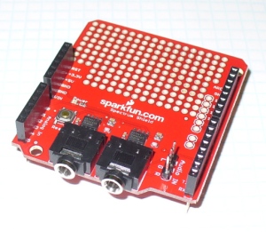
and then build your own circuit around it… or like most things in the Arduino world – get a shield. In this case, a derivative of the original Bliptronics shield by Sparkfun. It’s designed to pass through stereo audio via 3.5mm audio sockets and contains two MSGEQ7s, so we can do a stereo analyser:

As usual Sparkfun have saved a few cents by not including the stackable header sockets, so you’ll need to buy and solder those in yourself. There is also space for three header pins for direct audio input (left, right and common), which are useful – so if you can add those as well.

So now you have a shield that’s ready for use. Before moving forward let’s examine how the MSGEQ7 works for us. As mentioned earlier, it analyses seven frequency bands. These are illustrated in the following graph from the data sheet:

It will return the strengths of the audio at seven points – 63 Hz, 160 Hz, 400 Hz, 1 kHz, 2.5 kHz, 6.25 kHz and 16 kHz – and as you can see there is some overlap between the bands. The strength is returned as a DC voltage – which we can then simply measure with the Arduino’s analogue input and create a display of some sort. At this point audio purists, Sheldonites and RF people might get a little cranky, so once again – this is more for visual indication than any sort of calibration device.

However as an 8-pin IC a different approach is required to get the different levels. The IC will sequentially give out the levels for each band on pin 3- e.g. 63 Hz then 160 Hz then 400 Hz then 1 kHz then 2.5 kHz then 6.25 kHz  then 16 kHz then back to 63 Hz and so on. To start this sequence we first reset the IC by pulsing the RESET pin HIGH then low. This tells the IC to start at the first band. Next, we set the STROBE pin to LOW, take the DC reading from pin 3 with analogue input, store the value in a variable (an array), then set the STROBE pin HIGH. We repeat the strobe-measure sequence six more times to get the rest of the data, then RESET the IC and start all over again. For the visual learners consider the diagram below from the data sheet:

To demonstrate this process, consider the function

readMSGEQ7()

in the following example sketch:

// Example 48.1 - tronixstuff.com/tutorials > chapter 48 - 30 Jan 2013 
// MSGEQ7 spectrum analyser shield - basic demonstration
int strobe = 4; // strobe pins on digital 4
int res = 5; // reset pins on digital 5
int left[7]; // store band values in these arrays
int right[7];
int band;
void setup()
{
 Serial.begin(115200);
 pinMode(res, OUTPUT); // reset
 pinMode(strobe, OUTPUT); // strobe
 digitalWrite(res,LOW); // reset low
 digitalWrite(strobe,HIGH); //pin 5 is RESET on the shield
}
void readMSGEQ7()
// Function to read 7 band equalizers
{
 digitalWrite(res, HIGH);
 digitalWrite(res, LOW);
 for(band=0; band <7; band++)
 {
 digitalWrite(strobe,LOW); // strobe pin on the shield - kicks the IC up to the next band 
 delayMicroseconds(30); // 
 left[band] = analogRead(0); // store left band reading
 right[band] = analogRead(1); // ... and the right
 digitalWrite(strobe,HIGH); 
 }
}
void loop()
{
 readMSGEQ7();
 // display values of left channel on serial monitor
 for (band = 0; band < 7; band++)
 {
 Serial.print(left[band]);
 Serial.print(" ");
 }
 Serial.println();
// display values of right channel on serial monitor
 for (band = 0; band < 7; band++)
 {
 Serial.print(right[band]);
 Serial.print(" ");
 }
 Serial.println();
}

If you follow through the sketch, you can see that it reads both left- and right-channel values from the two MSGEQ7s on the shield, then stores each value in the arrays left[] and right[]. These values are then sent to the serial monitor for display – for example:

If you have a function generator, connect the output to one of the channels and GND – then adjust the frequency and amplitude to see how the values change. The following video clip is a short demonstration of this – we set the generator to 1 kHz and adjust the amplitude of the signal. To make things easier to read we only measure and display the left channel:


Keep an eye on the fourth column of data – this is the analogRead() value returned by the Arduino when reading the 1khz frequency band. You can also see the affect on the other bands around 1 kHz as we increase and decrease the frequency. However that wasn’t really visually appealing – so now we’ll create a small and large graphical version.

First we’ll use an inexpensive LCD, the I2C model from akafugu reviewed previously. To save repeating myself, also review how to create custom LCD characters from here.

With the LCD with have two rows of sixteen characters. The plan is to use the top row for the levels, the left-channel’s on … the left, and the right on the right. Each character will be a little bar graph for the level. The bottom row can be for a label. We don’t have too many pixels to work with, but it’s a compact example:

We have eight rows for each character, and the results from an analogueRead() fall between 0 and 1023. So that’s 1024 possible values spread over eight sections. Thus each row of pixels in each character will represent 128 “units of analogue read” or around 0.63 V if the Arduino is running from true 5 V (remember your AREF notes?). The sketch will again read the values from the MSGEQ7, feed them into two arrays – then display the required character in each band space  on the LCD.

Here’s the resulting sketch:

// Example 48.2 - tronixstuff.com/tutorials > chapter 48 - 30 Jan 2013 
// MSGEQ7 spectrum analyser shield and I2C LCD from akafugu
// for akafugu I2C LCD
#include "Wire.h"
#include "TWILiquidCrystal.h"
LiquidCrystal lcd(50);
// create custom characters for LCD
byte level0[8] = { 0b00000, 0b00000, 0b00000, 0b00000, 0b00000, 0b00000, 0b00000, 0b11111};
byte level1[8] = { 0b00000, 0b00000, 0b00000, 0b00000, 0b00000, 0b00000, 0b11111, 0b11111};
byte level2[8] = { 0b00000, 0b00000, 0b00000, 0b00000, 0b00000, 0b11111, 0b11111, 0b11111};
byte level3[8] = { 0b00000, 0b00000, 0b00000, 0b00000, 0b11111, 0b11111, 0b11111, 0b11111};
byte level4[8] = { 0b00000, 0b00000, 0b00000, 0b11111, 0b11111, 0b11111, 0b11111, 0b11111};
byte level5[8] = { 0b00000, 0b00000, 0b11111, 0b11111, 0b11111, 0b11111, 0b11111, 0b11111};
byte level6[8] = { 0b00000, 0b11111, 0b11111, 0b11111, 0b11111, 0b11111, 0b11111, 0b11111};
byte level7[8] = { 0b11111, 0b11111, 0b11111, 0b11111, 0b11111, 0b11111, 0b11111, 0b11111};
int strobe = 4; // strobe pins on digital 4
int res = 5; // reset pins on digital 5
int left[7]; // store band values in these arrays
int right[7];
int band;
void setup()
{
 Serial.begin(9600);
 // setup LCD and custom characters
 lcd.begin(16, 2);
 lcd.setContrast(24);
 lcd.clear();
lcd.createChar(0,level0);
 lcd.createChar(1,level1);
 lcd.createChar(2,level2);
 lcd.createChar(3,level3);
 lcd.createChar(4,level4);
 lcd.createChar(5,level5);
 lcd.createChar(6,level6);
 lcd.createChar(7,level7);
 lcd.setCursor(0,1);
 lcd.print("Left");
 lcd.setCursor(11,1);
 lcd.print("Right");
 pinMode(res, OUTPUT); // reset
 pinMode(strobe, OUTPUT); // strobe
 digitalWrite(res,LOW); // reset low
 digitalWrite(strobe,HIGH); //pin 5 is RESET on the shield
}
void readMSGEQ7()
// Function to read 7 band equalizers
{
 digitalWrite(res, HIGH);
 digitalWrite(res, LOW);
 for( band = 0; band < 7; band++ )
 {
 digitalWrite(strobe,LOW); // strobe pin on the shield - kicks the IC up to the next band 
 delayMicroseconds(30); // 
 left[band] = analogRead(0); // store left band reading
 right[band] = analogRead(1); // ... and the right
 digitalWrite(strobe,HIGH); 
 }
}
void loop()
{
 readMSGEQ7();
// display values of left channel on LCD
 for( band = 0; band < 7; band++ )
 {
 lcd.setCursor(band,0);
 if (left[band]>=895) { lcd.write(7); } else
 if (left[band]>=767) { lcd.write(6); } else
 if (left[band]>=639) { lcd.write(5); } else
 if (left[band]>=511) { lcd.write(4); } else
 if (left[band]>=383) { lcd.write(3); } else
 if (left[band]>=255) { lcd.write(2); } else
 if (left[band]>=127) { lcd.write(1); } else
 if (left[band]>=0) { lcd.write(0); }
 }
 // display values of right channel on LCD
 for( band = 0; band < 7; band++ )
 {
 lcd.setCursor(band+9,0);
 if (right[band]>=895) { lcd.write(7); } else
 if (right[band]>=767) { lcd.write(6); } else
 if (right[band]>=639) { lcd.write(5); } else
 if (right[band]>=511) { lcd.write(4); } else
 if (right[band]>=383) { lcd.write(3); } else
 if (right[band]>=255) { lcd.write(2); } else
 if (right[band]>=127) { lcd.write(1); } else
 if (right[band]>=0) { lcd.write(0); }
 }
}

If you’ve been reading through my tutorials there isn’t anything new to worry about. And now for the demo, with sound –

That would look great on the side of a Walkman, however it’s a bit small. Let’s scale it up by using a Freetronics Dot Matrix Display – you may recall these from Clock One. For some background knowledge check the review here.  Don’t forget to use a suitable power supply for the DMD – 5 V at 4 A will do nicely. The DMD contains 16 rows of 32 LEDs. This gives us twice the “resolution” to display each band level if desired. The display style is subjective, so for this example we’ll use a single column of LEDs for each frequency band, with a blank column between each one.

We use a lot of line-drawing statements to display the levels, and clear the DMD after each display. With this and the previous sketches, there could be room for efficiency – however I write these with the beginner in mind. Here’s the sketch:

// Example 48.3 - tronixstuff.com/tutorials > chapter 48 - 30 Jan 2013 
// MSGEQ7 spectrum analyser shield with a Freetronics DMD
// for DMD
#include "DMD.h" // for DMD
#include "SPI.h" // SPI.h must be included as DMD is written by SPI (the IDE complains otherwise)
#include "TimerOne.h"
#include "SystemFont5x7.h" // keep next two lines if you want to add some text
#include "Arial_black_16.h"
DMD dmd(1, 1); // creates instance of DMD to refer to in sketch
void ScanDMD() // necessary interrupt handler for refresh scanning of DMD
{ 
 dmd.scanDisplayBySPI();
}
int strobe = 4; // strobe pins on digital 4
int res = 5; // reset pins on digital 5
int left[7]; // store band values in these arrays
int right[7];
int band;
void setup()
{
 // for DMD
 //initialize TimerOne's interrupt/CPU usage used to scan and refresh the display
 Timer1.initialize( 5000 ); //period in microseconds to call ScanDMD. Anything longer than 5000 (5ms) and you can see flicker.
 Timer1.attachInterrupt( ScanDMD ); //attach the Timer1 interrupt to ScanDMD which goes to dmd.scanDisplayBySPI() 
 dmd.clearScreen( true ); //true is normal (all pixels off), false is negative (all pixels on)

 // for MSGEQ7
 pinMode(res, OUTPUT); // reset
 pinMode(strobe, OUTPUT); // strobe
 digitalWrite(res,LOW); // reset low
 digitalWrite(strobe,HIGH); //pin 5 is RESET on the shield
}
void readMSGEQ7()
// Function to read 7 band equalizers
{
 digitalWrite(res, HIGH);
 digitalWrite(res, LOW);
 for( band = 0; band < 7; band++ )
 {
 digitalWrite(strobe,LOW); // strobe pin on the shield - kicks the IC up to the next band 
 delayMicroseconds(30); // 
 left[band] = analogRead(0); // store left band reading
 right[band] = analogRead(1); // ... and the right
 digitalWrite(strobe,HIGH); 
 }
}
void loop()
{
 int xpos;
 readMSGEQ7();
 dmd.clearScreen( true ); 
 // display values of left channel on DMD
 for( band = 0; band < 7; band++ )
 {
 xpos = (band*2)+1;
 if (left[band]>=895) { dmd.drawLine( xpos, 15, xpos, 1, GRAPHICS_NORMAL ); } else
 if (left[band]>=767) { dmd.drawLine( xpos, 15, xpos, 3, GRAPHICS_NORMAL ); } else
 if (left[band]>=639) { dmd.drawLine( xpos, 15, xpos, 5, GRAPHICS_NORMAL ); } else
 if (left[band]>=511) { dmd.drawLine( xpos, 15, xpos, 7, GRAPHICS_NORMAL ); } else
 if (left[band]>=383) { dmd.drawLine( xpos, 15, xpos, 9, GRAPHICS_NORMAL ); } else
 if (left[band]>=255) { dmd.drawLine( xpos, 15, xpos, 11, GRAPHICS_NORMAL ); } else
 if (left[band]>=127) { dmd.drawLine( xpos, 15, xpos, 13, GRAPHICS_NORMAL ); } else
 if (left[band]>=0) { dmd.drawLine( xpos, 15, xpos, 15, GRAPHICS_NORMAL ); }
 }

 // display values of right channel on DMD
 for( band = 0; band < 7; band++ )
 {
 xpos = (band*2)+18;
 if (right[band]>=895) { dmd.drawLine( xpos, 15, xpos, 1, GRAPHICS_NORMAL ); } else
 if (right[band]>=767) { dmd.drawLine( xpos, 15, xpos, 3, GRAPHICS_NORMAL ); } else
 if (right[band]>=639) { dmd.drawLine( xpos, 15, xpos, 5, GRAPHICS_NORMAL ); } else
 if (right[band]>=511) { dmd.drawLine( xpos, 15, xpos, 7, GRAPHICS_NORMAL ); } else
 if (right[band]>=383) { dmd.drawLine( xpos, 15, xpos, 9, GRAPHICS_NORMAL ); } else
 if (right[band]>=255) { dmd.drawLine( xpos, 15, xpos, 11, GRAPHICS_NORMAL ); } else
 if (right[band]>=127) { dmd.drawLine( xpos, 15, xpos, 13, GRAPHICS_NORMAL ); } else
 if (right[band]>=0) { dmd.drawLine( xpos, 15, xpos, 15, GRAPHICS_NORMAL ); }
 }
}

… and here it is in action:

Conclusion

At this point you have the knowledge to use the MSGEQ7 ICs to create some interesting spectrum analysers for entertainment and visual appeal – now you just choose the type of display enjoy the results. And if you enjoyed this article, or want to introduce someone else to the interesting world of Arduino – check out my book (now in a fourth printing!) “Arduino Workshop”.

Have fun and keep checking into tronixstuff.com. Why not follow things on twitterGoogle+, subscribe  for email updates or RSS using the links on the right-hand column, or join our forum – dedicated to the projects and related items on this website.

The post Tutorial: Arduino and the MSGEQ7 Spectrum Analyzer appeared first on tronixstuff.

3d printed hexapod robot

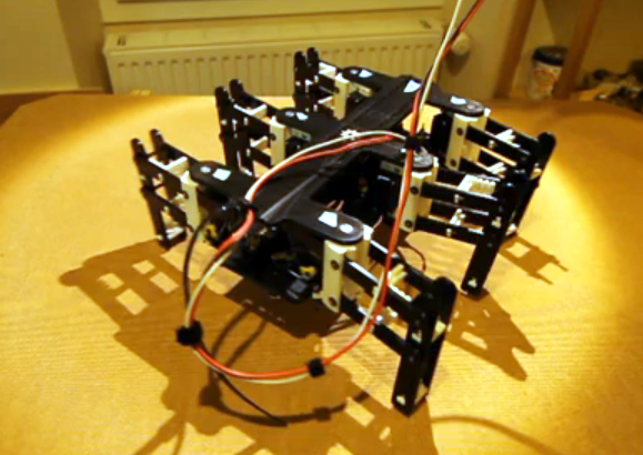
This hexapod was made almost entirely via 3d printing (translated). The parts that you need to supply include a few fasteners to make connections, twelve servo motors, and a method of driving them. As you can see in the video after the break, all those parts come together into a little robot that functions quite well. The only thing that we think is missing are some grippy feet to help prevent slipping.

[Hugo] calls the project Bleuette. It is completely open source, with the cad files and source code available on his Github repository. There is additional information in the wiki page of that repo. This gives us a good look at the electronic design. He’s controlling the legs with an Arduino, but it’s all dependent on his own shield which features a PIC 18F452 to take care of the signals used to drive all of the servo motors. The board also has some peripherals to monitor the current draw and regulate the incoming power.


Filed under: robots hacks
Hack a Day 30 Jan 20:01

Data-logging made simple with Arduino

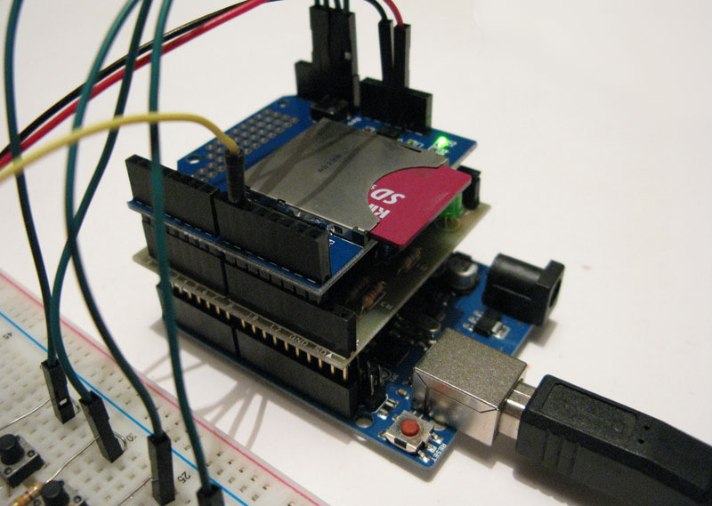
One of the best capabilities provided by Arduino regards its very high modularity, which helps users to quickly translate ideas into physical artifact, as practically demonstrated by Mauro, which shows on his blog how to build a simple data-logger by properly combining different shields. By using few additional components (mainly resistors and buttons) a fully-functional data logger can be easily implemented.

More information can be found here.

[Via: Mauro Alfieri's blog]

Arduino Blog 23 Jan 20:00