Posts with «shield» label

Bread Online is a Bread Maker for the Internet of Things

An engineering student at the University of Western Macedonia has just added another appliance to the ever-growing list of Internet enabled things. [Panagiotis] decided to modify an off-the-shelf bread maker to enable remote control via the Internet.

[Panagiotis] had to remove pretty much all of the original control circuitry for this device. The original controller was replaced with an Arduino Uno R3 and an Ethernet shield. The temperature sensor also needed to be replaced, since [Panagiotis] could not find any official documentation describing the specifications of the original. Luckily, the heating element and mixer motor were able to be re-used.

A few holes were drilled into the case to make room for the Ethernet connector as well as a USB connector. Two relays were used to allow the Arduino to switch the heating element and mixer motor on and off. The front panel of the bread maker came with a simple LCD screen and a few control buttons. Rather than let those go to waste, they were also wired into the Arduino.

The Arduino bread maker can be controlled via a web site that runs on a separate server. The website is coded with PHP and runs on Apache. It has a simple interface that allows the user to specify several settings including how much bread is being cooked as well as the desired darkness of the bread. The user can then schedule the bread maker to start. Bread Online also comes with an “offline” mode so that it can be used locally without the need for a computer or web browser. Be sure to check out the video demonstration below.

[Thanks Minas]


Filed under: Arduino Hacks, cooking hacks

Every word is like an unnecessary stain on silence

« Every word is like an unnecessary stain on silence and nothingness » is a sentence from Samuel Beckett but also the title of Eugenio Ampudia’s last artwork created and installed with the support of Ultra-lab  and running on Arduino Mega and GSM Shield:

The exhibition room has in its center a rectangular mirror made of water that reflects the room and the visitors. The perfect still water, metaphor of silence, is broken by the irruption of sporadic waves. These movements, the stain on silence, are provoked by the visitors’ interactions. In the heart of the water tank, a dispositive is able to receive calls and to open a valve. To each visitor’s call, so a series of movements is generated and break the calm.

Ultra-lab realized the technical part of the artwork thanks to an Arduino Mega, the Arduino GSM shield and various valves open and close by the Arduino Mega when a call is received by the shield. The dispositive is particularly interesting for its adaptation in a water context and for connecting valves.

Thanks to it, the artwork succeed to express beautifully the paradox between a destructive attraction for words and communication to which it’s hard to resist in order to prefer a finally inaccessible contemplation.

The work can be visited in the exhibition room Abierto X Obras in in the Spanish art center Matadero Madrid until the 17th of May 2015 and below you can watch a video interview with the artist:

Arduino Blog 09 Mar 20:01

An Arduino Device that Monitors Your External IP Address

[Bayres’] dad setup a webcam as a surveillance camera for a remote property. The only problem was that the only stable Internet connection they could get at this property was DSL. This meant that the external IP address of the webcam would change somewhat often; the needed a way to keep track of the external IP address whenever it changed. That’s when [Bayres] built a solution using Arduino and an Ethernet shield.

The main function of this device is to monitor the public IP address and report any changes. This is accomplished by first making a request to checkip.dyndns.org. This website simply reports your current public IP address. [Bayres] uses an Arduino library called Textfinder in order to search through the returned string and identify the IP address.

From there, the program compares this current value to the previous one. If there is any change, the program uses the Sendmail() function to reach out to an SMTP server and send an e-mail alert to [Beyres’] dad. The system also includes a small LCD. The Arduino outputs the current IP address to this display, making it easy to check up on the connection. The LCD is driven by 74HC595 shift register in order to conserve pins on the Arduino.

The system is also designed with a pretty slick setup interface. When it is booted, the user can enter a configuration menu via a Serial terminal. This setup menu allows the user to configure options such as SMTP server, email address, etc. These variables are then edited and can be committed to EEPROM as a more permanent storage solution. Whenever the system is booted, these values are read back out of the EEPROM and returned to their appropriate variables. This means you can reconfigure the device on the fly without having to edit the source code and re-upload.


Filed under: Arduino Hacks

E-Paper Barcode 39

E-Paper (or Electronic paper) is a display technology that mimics the appearance of ordinary ink on paper. E-paper displays do not emit light, rather they reflect light, thus making them much more comfortable to read and provide a wider viewing angle than most light emitting displays (source: Wikipedia).

I printed something to an E-paper display, unplugged it, and could still read the message clearly months later. These E-paper displays are great for showing information that is static for long periods. You only need to provide power when the data or information needs updating.

Barcodes are used everywhere, and one of the simplest Barcodes to generate is the Code 39 format (also known as Code 3 of 9). I used an E-paper shield and E-paper module to display a number in this barcode format. I then tested it with a Barcode reader and it worked perfectly.
This tutorial will show you how to send a number to the Arduino from the Serial Monitor, and display the Barcode on the E-paper module.

Note: If you are using an Arduino UNO (or compatible), you will also need to get a micro SDHC card.
 

The Video


The video will show you how to assemble the shield and the module onto the Arduino, and also how to install the SDHC card.


Parts Required:

Library Download


To use the e-paper shield, you will need to download the Small e-paper Shield library.
This library will allow you to use the following functions on the e-paper shield:
  • begin : to set up the size of the e-paper panel
  • setDirection : to set up the display direction
  • drawChar : to display a Character at a specified position
  • drawString : to display a String of characters at a specified position
  • drawNumber and drawFloat : to display a number
  • drawLine : to draw a line
  • drawHorizontalLine : to draw a horizontal line
  • drawVerticalLine : to draw a vertical line
  • drawCircle : to draw a circle
  • fillCircle : to draw and fill a circle
  • drawRectangle : to draw a rectangle
  • fillRectangle : to draw and fill a rectangle
  • drawTriangle : to draw a triangle
You can also draw an image to the e-paper shield.

For more information on how to use these functions, please visit the seeedstudio wiki. If you are unfamiliar with installing libraries - then have a look at the following sites:

Barcode 39 Info

Barcode 39 (or Code 3 of 9) is a barcode that consists of black and white vertical lines. These lines can be thick or thin. Each character can be coded using 9 alternating black and white bars. The barcode always starts with a black bar, and ends with a black bar.

If you code using thin lines only, then each character can be coded using a total of 12 bars. A wide black line is essentially two thin black lines next to each other. Same goes for a wide white line. Because there are now only 2 options (black or white), you can create a binary code. I used a 1 for black bars, and 0 for white bars. If there was a thick black bar, then this would be represented with a 11. A thick white bar would be 00.

Each barcode sequence starts and ends with a hidden * character. Therefore if you were to display just the number 1, you would have to provide the code for *1*.

  • * = 100101101101
  • 1 = 110100101011
  • * = 100101101101
Notice that each character starts with a 1 and ends with a 1.
Something also to take note of: is that each character is separated by a thin white line (and not represented in the binary code).

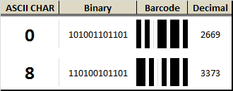
All of these 0's and 1's can get a bit confusing, so I decided to represent these binary numbers as decimals. For example, the picture below shows how a 0 and an 8 would be coded (without the *):


The table below provides the binary and decimal codes for each number used in this tutorial. I have also included for your own reference, each letter of the alphabet, however I did not use these in this tutorial.

The binary representation of each character in this table was obtained from this site.
www.barcodeisland.com is a great resource of information about barcodes.

I adapted their binary code into a decimal equivalent, and therefore had to create my own table.


Arduino Sketch


  1
2
3
4
5
6
7
8
9
10
11
12
13
14
15
16
17
18
19
20
21
22
23
24
25
26
27
28
29
30
31
32
33
34
35
36
37
38
39
40
41
42
43
44
45
46
47
48
49
50
51
52
53
54
55
56
57
58
59
60
61
62
63
64
65
66
67
68
69
70
71
72
73
74
75
76
77
78
79
80
81
82
83
84
85
86
87
88
89
90
91
92
93
94
95
96
97
98
99
100
101
102
103
104
105
106
107
108
109
110
111
112
113


/* ===============================================================
      Project: Display Barcodes on an e-Paper Panel
       Author: Scott C
      Created: 6th January 2015
  Arduino IDE: 1.0.5
      Website: http://arduinobasics.blogspot.com/p/arduino-basics-projects-page.html
  Description: This project will allow you to send a number from the Serial 
               Monitor to the Arduino. The number will then be displayed on 
               the e-Paper panel as a Code-39 barcode (and text).
================================================================== */

#include <ePaper.h>
#include <SPI.h>
#include <SD.h>
#include "GT20L16_drive.h"

const int maxBarcodeSize = 10; // set the maximum barcode size to 10 digits
int barcode[maxBarcodeSize]; // initialise the barcode array to the maximum 10 digits
int barcodeText[maxBarcodeSize]; // initialise the barcodeText array to the maximum 10 digits
int barcodePos; // Used to identify each digit within the barcode
int barcodeLength; // Used to identify the actual length of the barcode

/*  The following array holds the decimal code for each digit (0-9). 
    Each digit can be converted to binary and then drawn as a barcode.
                         0     1     2     3     4     5     6     7     8     9         */
int barcodeDecimal[] = {2669, 3371, 2859, 3477, 2667, 3381, 2869, 2651, 3373, 2861};

int astrix = 2413; // "*" character decimal code used at beginning and end of barcode sequence


/*  When drawBarcode = "no", the program will not draw the barcode on the e-paper panel
    When drawBarcode = "yes", the command to draw the barcode on the e-paper panel will be triggered. */
String drawBarcode = "no";


/*  This variable is the x Position on the e-Paper panel screen */
int xPosition;


void setup(){
    Serial.begin(9600); // Initialise Serial communication
    EPAPER.begin(EPD_2_0); // Set the e-Paper panel size to 2 inches
    EPAPER.setDirection(DIRNORMAL); // Set the e-Paper panel display direction (to Normal)
    eSD.begin(EPD_2_0); // Prepares the SD card
    GT20L16.begin(); // Initialise the GT20L16 font chip on the e-Paper panel
    barcodePos = 0;                    // Set the barcode digit to the first digit in the barcode
    EPAPER.clear_sd(); // Clear the screen when starting sketch
    
    EPAPER.drawString("http://arduinobasics", 10, 20); //splash screen text
    EPAPER.drawString(".blogspot.com", 60, 40);
    
    EPAPER.display(); // Display the splash screen
}


void loop(){
  
    // The Arduino will wait until it receives data from the Serial COM port
    
    while (Serial.available()>0){
      barcodeText[barcodePos] = Serial.read();
        
      if(barcodeText[barcodePos]>47 && barcodeText[barcodePos]<58){ // A number was sent
         barcode[barcodePos] = barcodeText[barcodePos]-48;            // Convert the decimal value from the serial monitor to a Number
      } 
      
      if(barcodeText[barcodePos]==46){ // If a "." is detected, then barcode is complete
        barcodeLength = barcodePos;                   // Set the length of the barcode (used later)
        drawBarcode = "yes"; // We can now draw the barcode
        
      }
      
      if(barcodePos>(maxBarcodeSize-1)){ // Check if maximum barcode length has been reached
       barcodeLength = barcodePos;                    // Set the length of the barcode (used later)
       drawBarcode = "yes"; // We can now draw the barcode
      }
     
       barcodePos++;                                  // Move to the next barcode digit
    }
    
    if(drawBarcode == "yes"){ // Only draw the barcode when drawBarcode = "yes"
      
      EPAPER.clear_sd(); // Clear the e-Paper panel in preparation for barcode
      xPosition = 15;                                 // Set the initial white-space on the left
      drawBCode(astrix, ' '); // Each barcode starts with an invisible *
      
      for(int digit=0; digit<barcodeLength; digit++){ // Start drawing the barcode numbers
        drawBCode(barcodeDecimal[barcode[digit]], barcodeText[digit]);  // Call the drawBCode method (see below)
      }
      
      drawBCode(astrix, ' '); // Each barcode ends with an invisible *
      EPAPER.display(); // Show the barcode image and text
      
      drawBarcode = "no"; // Stop it from drawing again until next barcode sequence sent
      barcodePos=0;                                   // Re-initialise the position back to first digit (in preparation for the next barcode)
    }
}


//The drawBCode method is the key method for drawing the barcode on the e-paper panel
void drawBCode(int bCode, char bCodeText){
  xPosition++;                                        // There is a white space between each digit
  for (int barPos = 11; barPos > -1; barPos--){ // Cycle through the binary code for each digit. Each digit is made up of 11 bars
    xPosition++;                                      // Advance the xPosition to draw the next bar (white or black)
    if(bitRead(bCode, barPos)==1){ // If the binary digit at this position is a 1, then draw a black line
      EPAPER.drawVerticalLine(xPosition, 10, 60); // This draws the individual Bar (black - only)
    }                                                 // If the binary digit is a 0, then it is left blank (or white).
  }
  EPAPER.drawChar(bCodeText, xPosition-9, 75); // Draw the human readable (text) portion of the barcode
}


There is something weird about the E-paper shield library which tends to display the word "temperature:" in the Serial monitor when opened, and with each serial transmission. Don't worry about this. Just ignore it.'


This tutorial shows you how to create your own renewable barcodes. While this only handles numbers at this stage, it could just as easily be upgraded to handle text as well. If you liked this tutorial, please give it a google+ thumbs up, share it with your friends, or just write a comment. Thankyou for visiting my blog.


If you like this page, please do me a favour and show your appreciation :

 
Visit my ArduinoBasics Google + page.
Follow me on Twitter by looking for ScottC @ArduinoBasics.
Have a look at my videos on my YouTube channel.


However, if you do not have a google profile...
Feel free to share this page with your friends in any way you see fit.

GSM Controlled Star Light: A xmas tutorial for Intel Galileo

We recently posted on Intel Makers Community the first of a series of educational tutorial focused on Intel Galileo Gen 2. Our team worked on  a smart Christmas star able to receive sms and change pattern according to it. The bill of materials contains also an Arduino GSM Shield, a Proto Shield and some flexible  LED  strips:

To kick off a festive mood, we decided to adapt a typical Scandinavian tradition. In December, many people will decorate their homes by hanging large paper stars inside their windows. The stars usually have a single bulb inside that casts a warm, welcoming glow.

We thought we’d try to make this tradition a bit more merry by making it interactive. By sending text messages, we will change the blink pattern and color of the star.

This project is a fun and easy introduction on how to use the Intel Galileo Gen 2 board and the Arduino GSM shield. After making this tutorial, try modifying the code to change the patterns or taking the functions to insert GSM connectivity into your own projects.

Happy Holidays!

Follow the link and make it as well!


Arduino Blog 19 Dec 19:08

Pimp your ikea lamp into a customized death star

Ikea hacks are well widespread in the maker movement and David Bliss, founder at Nurun, did a great job transforming the Death Star inspired PS 2014 Pendant Lamp into something more dynamic.

The lamp was pimped up with an Arduino Uno and Arduino Motor Shield, NeoPixel LEDs and other components you can see in the illustration.

The detailed description of the project is on his blog , the code on github and the final result in the following video:

Arduino Blog 26 Nov 22:41
arduino  featured  ikea  led  motor  shield  

Programmable Lithium Charger Shield for Arduino

Surely you need yet another way to charge your lithium batteries—perhaps you can sate your desperation with this programmable multi (or single) cell lithium charger shield for the Arduino<! Okay, so you’re not><em>hurting</em> for another method of juicing up your batteries. If you’re a regular around these parts of the interwebs, you’ll recall the <a href="http://hackaday.com/2014/09/21/a-li-ion-battery-charging-guide/">lithium charging guide</a> and that <a href="http://hackaday.com/2014/09/05/an-obsessively-thorough-battery-and-more-showdown/">rather incredible, near-encyclopedic rundown of both batteries and chargers</a>, which likely kept your charging needs under control.</p> <p>That said, this shield by Electro-Labs might be the perfect transition for the die-hard-’duino fanatic looking to migrate to tougher projects. The build features an LCD and four-button interface to fiddle with settings, and is based around an LT1510 constant current/constant voltage charger IC. You can find the schematic, bill of materials, code, and PCB design on the Electro-Labs webpage, as well as a brief rundown explaining how the circuit works. Still want to add on the design? Throw in <a href="http://hackaday.com/2014/07/16/finally-an-easy-to-make-holder-for-lithium-ion-batteries/">one of these Li-ion holders</a> for quick battery swapping action.</p> <p>[via <a href="http://embedded-lab.com/blog/?p=9644">Embedded Lab</a>]</p><br />Filed under: <a href="http://hackaday.com/category/arduino-hacks/">Arduino Hacks</a>, <a href="http://hackaday.com/category/microcontrollers/">Microcontrollers</a> <a><img src="http://feeds.wordpress.com/1.0/comments/hackadaycom.wordpress.com/138748/" /></a> <img src="http://pixel.wp.com/b.gif?host=hackaday.com&blog=4779443&post=138748&subd=hackadaycom&ref=&feed=1" />

Medical Tricorder Mark I

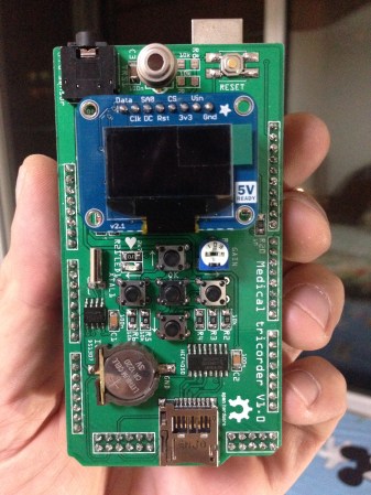
A handheld tricorder is as good a reason as any to start a project. The science-fiction-derived form factor provides an opportunity to work on a lot of different areas of hardware development like portable power, charging, communications between sensor and microcontroller. And of course you need a user interface so that the values being returned will have some meaning for the user.

[Marcus B] has done a great job with all of this in his first version of a medical tricorder. The current design hosts two sensors, one measures skin temperature using infrared, the other is a pulse sensor.

For us it’s not the number of sensors that makes something a “tricorder” but the ability of the device to use those sensors to make a diagnosis (or to give the user enough hints to come to their own conclusion). [Marcus] shares similar views and with that in mind has designed in a real-time clock and an SD card slot. These can be used to log sensor data over time which may then be able to suggest ailments based on a known set of common diagnosis parameters.

Looking at the image above you may be wondering which chip is the microcontroller. This build is actually a shield for an Arduino hiding underneath.

There’s a demonstration video after the break. And if you find this impressive you won’t want to miss the Open Source Science Tricorder which is one of the finalists for the 2014 Hackaday Prize.


Filed under: Medical hacks
Hack a Day 08 Nov 03:01

Wood Lizzie is a DIY Soap Box Cart controlled via Wi-Fi

In the following 10-minute video, the Currah team is showing us all the details of Wood Lizzie, a project experimenting with Arduino Mega and Wi-Fi Shield, a very flexible steering system and the virtually unlimited control range afforded by WiFi and Internet Protocol:

The original plan was to construct one of the two-wheeled robots very popular with hobbyists but it was eventually decided that the resulting vehicle would be of very limited application and capable only of traversing smooth surfaces. However, note that the current design can be viewed as the drive of a two-wheeled robot coupled with a trailer by means of a 360 degree pivot. A slip ring capsule within the pivot enables the heavy battery and bulky control system to be separated from the drive and located on the trailer thereby distributing weight evenly between the four wheels.

DIY soap-carts were pretty common among kids in the first part of the 20th century and built from old pram wheels, scrap wood and, typically, soap boxes. They could provide a lot of fun for the family at very low cost and in recent years there’s a new interest in them especially to those appreciating their vintage look!


Video mixing chess games on tv in Norway using Ethernet Shield

Heidi Røneid with an Arduino Ethernet microprocessor. (Photo: Tore Zakariassen, NRK)

When The Norwegian Broadcasting (NRK) planned the television broadcast of the Chess Olympiad 2014 in Tromsø, Norway, they encountered a challenge: how to mix video, graphics and the results of many ongoing chess games simultaneously, requiring 16 cameras for the games going on at the same time?

On their blog you can find a long and nice post about how they found the solution using Arduino Uno, Arduino Ethernet Shield and the library for Arduino to control such Atem switchers written by Kasper Skårhøj:

At first, the idea was to use a computer with a webcam for each of the 16 games, then mix video images, background animation and results in software on each of them.

Afterwards the finished mix of images would be streamed to separate channels in our web player, so that the online audience would be able to choose which game they wanted to follow. This solution would also provide our outside broadcasting van (OB van) with 16 finished video sources composed of video, graphics and results. This would make the complex job of mixing all video signals much easier.

After thorough thinking we came to the conclusion that for our web-audience, it would be better to skip the stream of individual games, and spend our resources on building websites that could present all games in the championship via HTML in real time. This would also give the audience the opportunity to scroll back and forth in the moves and recall all the previous games in the championship. We started working on it immediately, and you can find the result on our website nrk.no/sjakk.

Arduino Blog 28 Aug 19:14
arduino  chess  ethernet  featured  games  norway  shield  tv