EasyEDA RGB5050 LED Scroll Bar
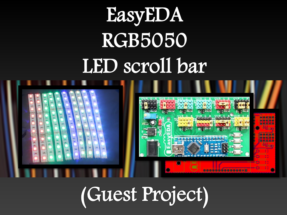
Guest Post Disclaimer
This is a guest post by the EasyEDA team. I would like to thank EasyEDA for providing this tutorial for everyone to enjoy. All information within this post was provided by EasyEDA.
Description
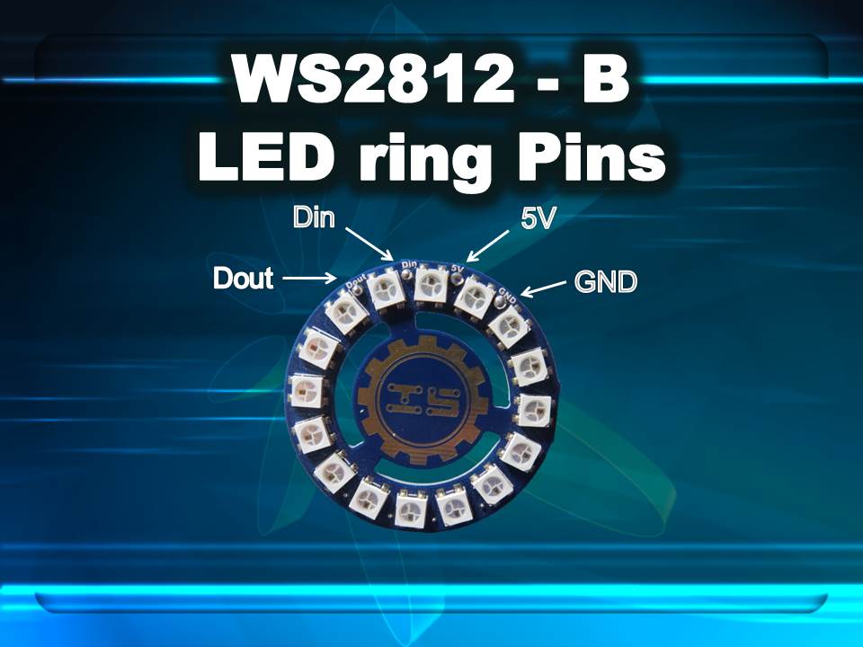
Parts Required:
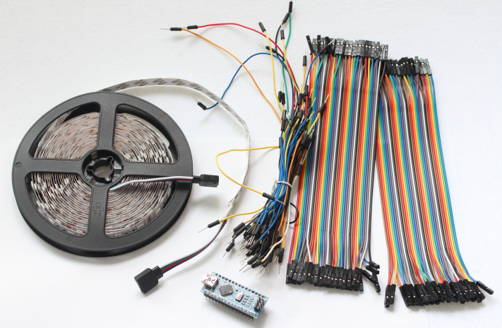
Image source: EasyEDA
Arduino Libraries and IDE
No libraries are required for this project. The Arduino IDE can be downloaded from the Arduino website. Here is the download link.
ARDUINO CODE:
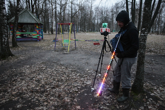
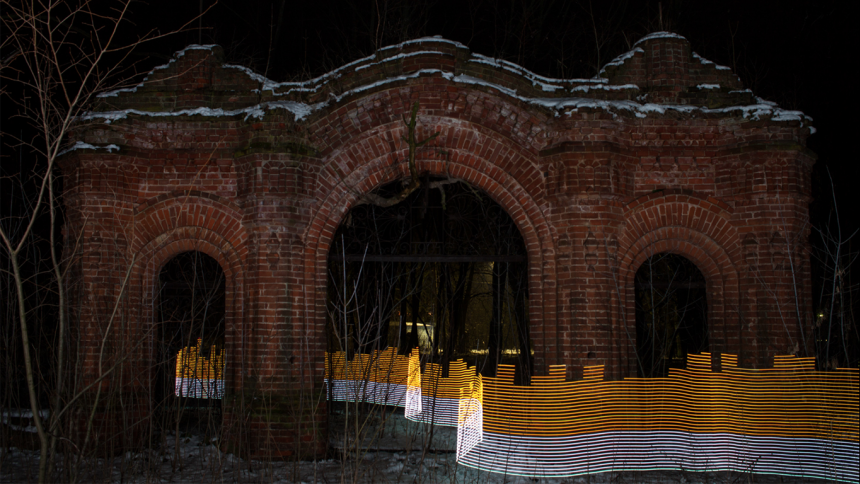
Preparing the LED strips

Image source: EasyEDA
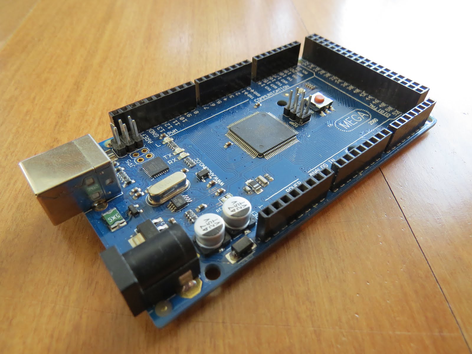
Designing the Control Board
I have made a custom control board that incorporates an Arduino Nano. The control board is used to boost the incoming signal from Arduino and lights up the corresponding LED strips.

Image source: EasyEDA
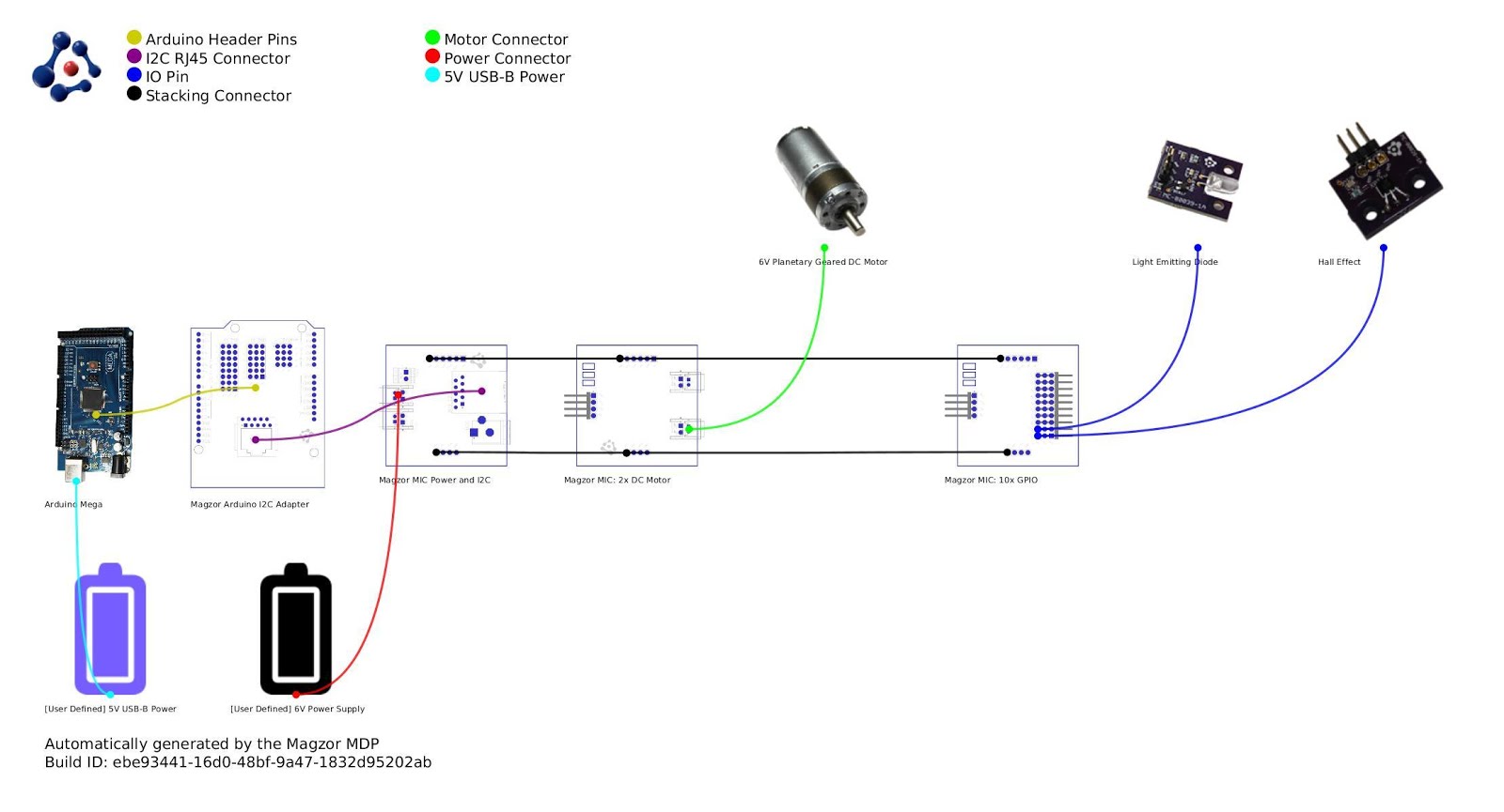
Control Board Circuit diagram
Schematic
You can access the actual EasyEDA schematic by clicking on the image below:
Image source: EasyEDA
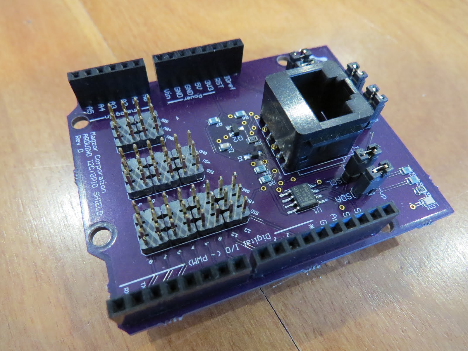
PCB Board Design
Here is the PCB board design for this project.
You can access the actual EasyEDA design by clicking on the image below.
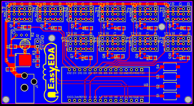
Image source: EasyEDA
PCB Fabrication
After completing the PCB design, you can click on the Fabrication icon.
You will then have access to the PCB order page which will allow you to download your PCB Gerber files that can be sent to any manufacturer. However it is a lot easier (and cheaper) to order it directly from EasyEDA.
Here you can select:
- the number of PCBs you want to order
- the number of copper layers you need
- the PCB thickness
- copper weight
- and even the PCB color

Image source: EasyEDA
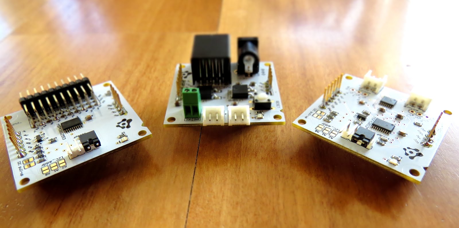
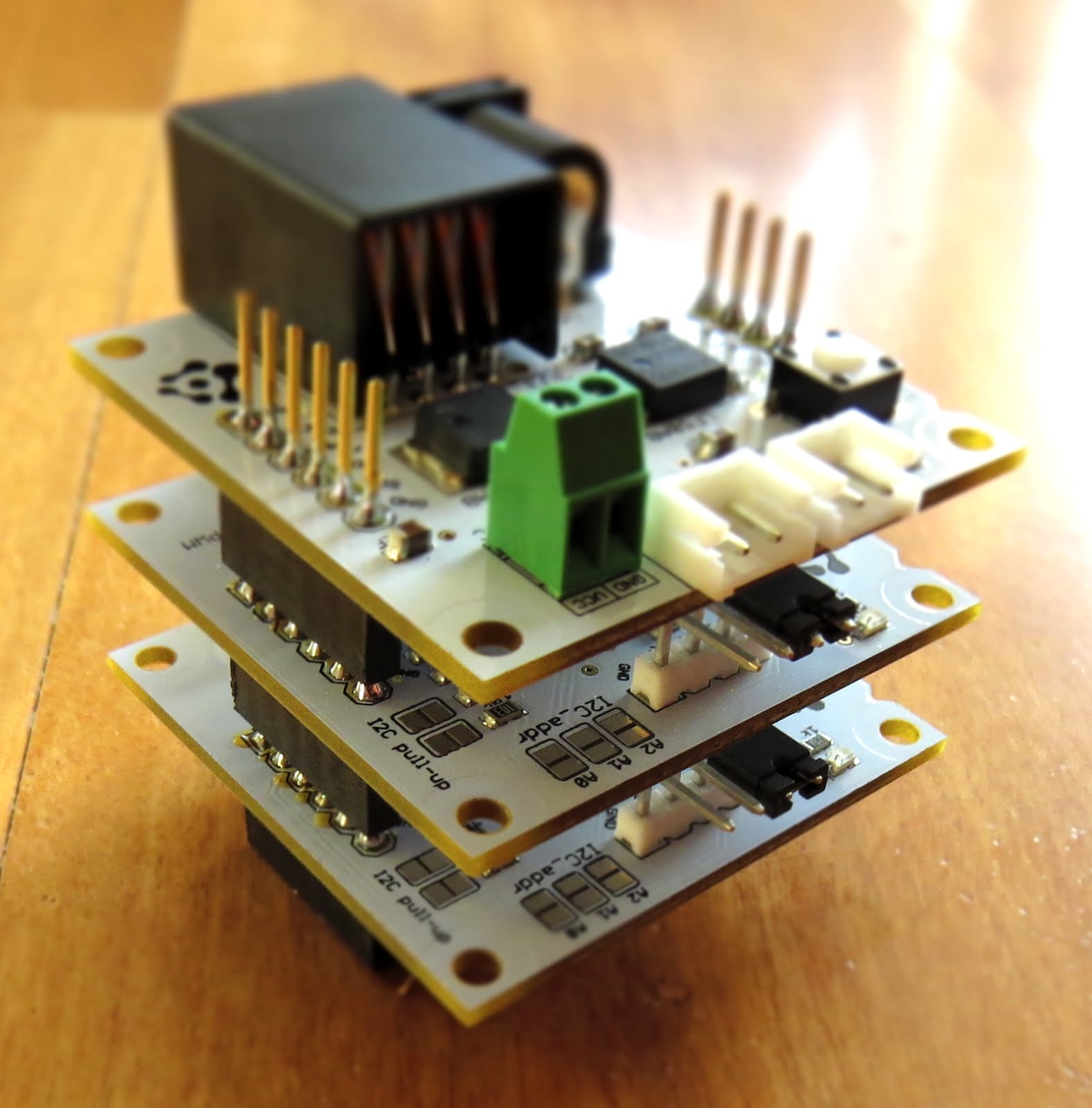
PCB final product
When I received the PCBs, I am quite impressed with the quality, they are pretty nice.
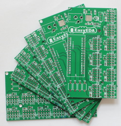
Image source: EasyEDA
PCB Build of Materials
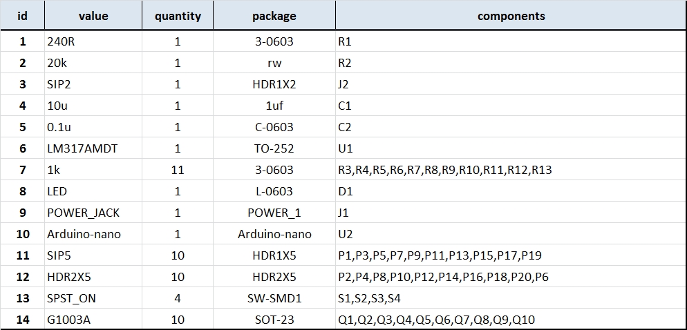
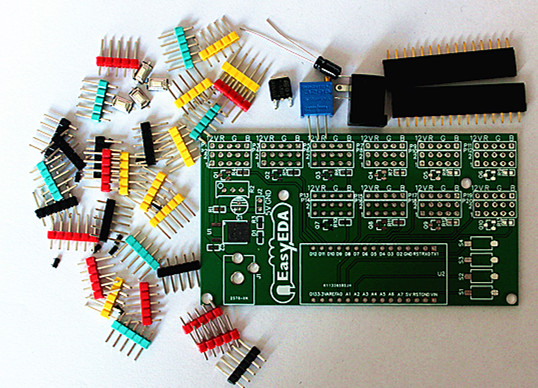
Image source: EasyEDA
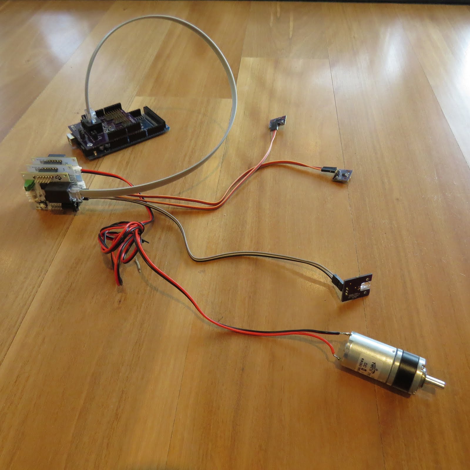
PCB connections

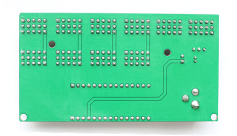


Image source: EasyEDA
Project Video
Concluding comments
Hope you like this RGB light effects project, do try it out and post your feedback below.
Disclaimer:
This is a guest blog post by the EasyEDA team. All information within this post was provided by EasyEDA.