Few things beat a sturdy, home-built desk — especially when it’s jam-packed with over 1200 WS2812 LEDs.
[nolobot] and his bother struggled with setting up and squaring-off the t-slotted, extruded aluminium frame which makes up the desk. He recommends practicing with a smaller frame for anyone else attempting a similar build. The surface of the desk has a few inches between the polycarbonate top and the 1/4″ plywood painted black serving as the substrate for the LEDs. Those LEDs come in strip form but still required several hundred solders, and wiring headaches in an attempt to make future upgrades manageable. Dozens of support bolts with adjustable feet support the desk surface throughout. These all had to be individually adjusted and can be made out if you look closely at the demo videos.
An Arduino Mega controls the LEDs with the help of the FastLED library. Custom code was necessary because one of the major issues [nolobot] faced was the power draw. 1200 LEDs at 5V draw quite a bit of current, so the LEDs were coded to peak at about 50% brightness. The matrix was split into different banks, while also limiting the 40A PSU to only 15A.
[Paul] created a frame that uses an Arduino and LEDs to create a slow motion illusion of a delicate item (like a flower or a feather). The effect is striking as you can see in the video below.
[Paul] had seen similar projects (both one-offs and sold as a product), but wanted to do his own take on it. The principle is simple: The device vibrates the objects at one frequency and strobes LEDs at a slightly different frequency (80 and 79.5 Hz, in this case). The difference between the frequencies (the beat frequency) is what your eye perceives as a very slow (0.5 Hz, here) motion.
Once you know the secret behind the device, it is not very complicated to create. The woodworking for the frame is the bulk of the work. An Arduino excites an electromagnet to vibrate the subject items. It also pulses the LED strips to achieve the strobe effect. It’s simple, striking, and a show piece. It seems like everyone has been building their own magic mirror project, but we proffer this awesome concept as the next big thing everyone should try on their own workbench. Let’s check out a few other examples to get you thinking.
One of [Paul’s] inspirations was Time Frame, which appears in the second video, below. You can find its code on GitHub. It also uses an Arduino to create the same effect. The other inspiration was Slow Dance, which we covered earlier. We’ve also seen a similar trick played with water droplets.
There’s no shortage of Arduino-based clocks around. [Mr_fid’s] clock, though, gets a second look because it is very unique looking. Then it gets a third look because it would be very difficult to read for the uninitiated.
The clock uses three Xs made of LEDs. There is one X for the hours (this is a 24-hour clock), another for the minutes, and one for the seconds. The left side of each X represents the tens’ digit of the number, while the right-side is the units.
But wait… even with two segments on each side of the X, that only allows for numbers from 0 to 3 in binary, right? [Mr_fid] uses another dimension–color–to get around that limitation. Although he calls this a binary clock, it is more accurately a binary-coded-decimal (BCD) clock. Red LEDs represent the numbers one to three. Green LEDs are four to six. Two blue segments represent seven to nine. It sounds complicated, but if you watch the video, below, it will make sense.
This isn’t [Mr_fid’s] first clock. He is using a DS1307 real time clock module to make up for the Arduino’s tendency to drift. Even if you aren’t interested in the clock, the mounting of the LEDs with plastic–and the issues he had isolating them from each other–might come in handy in other displays.
We’ve seen a lot of Arduino clocks over the years, including some that talk. We’ve even seen some that qualify as interactive furniture, whatever that is.
The WS2812 is an amazing piece of technology. 30 years ago, high brightness LEDs didn’t even exist yet. Now, you can score RGB LEDs that even take all the hard work out of controlling and addressing them! But as ever, we can do better.
Riffing on the ever popular Adafruit NeoPixel library, [Harm] created the WS2812FX library. The library has a whole laundry list of effects to run on your blinkenlights – from the exciting Hyper Sparkle to the calming Breathe inspired by Apple devices. The fantastic thing about this library is that it can greatly shorten development time of your garden-variety blinkables – hook up your WS2812s, pick your effect, and you’re done.
[Harm]’s gone and done the hard yards, porting this to a bevy of platforms – testing it on the Arduino Nano, Uno, Micro and ESP8266. As a proof of concept, they’ve also put together a great demonstration of the software – building some cute and stylish Christmas decorations from wood, aluminium, and hacked up Christmas light housings. Combining it with an ESP8266 & an app, the effects can be controlled from a smartphone over WiFi. The assembly video on YouTube shows the build process, using screws and nails to create an attractive frame using aluminium sheet.
This project is a great example of how libraries and modern hardware allow us to stand on the shoulders of giants. It’s quicker than ever to build amazingly capable projects with more LEDs than ever. Over the years we’ve seen plenty great WS2812 projects, like this sunrise alarm clock or this portable rave staff.
As always, blink hard, or go home. Video after the break.
A tiny board which can turn your computer into an - Oscilloscope - Waveform generator - Logic analyser - Multimeter - and Power supply.
Great for makers or hobbyists with limited bench space or limited funds. Perfect for students and anyone starting out in the field of electronics
As you will see in the video below, I take a prototype of the EspoTek Labrador for a spin, and try out all of the functions that this board can provide.
I use an Arduino UNO, a couple of 433MHz RF modules, some LEDs and a speaker to see just how useful this board will be for my hobby requirements.
I have been wanting an Oscilloscope for quite some time, and while this board does not necessarily win against a benchtop oscilloscope on a side-by-side comparison of specifications, it does make up for it somewhat in terms of price, space (or footprint), usability, and wide range of functionality. But does it actually function as an oscilliscope? Is it useful ? Will it do what I need it to do? Or will I still need to buy that expensive oscilloscope that I have been saving up for?
Have a look at my review below, and tell me what you think.
With All Hallow’s Eve looming close, makers have the potential to create some amazing costumes we’ll remember for the rest of the year. If you’re a fan of the hugely addict-*cough* popular game Minecraft, perhaps you’ve considered cosplaying as your favorite character skin, but lacked the appropriate props. [Graham Kitteridge] and his friends have decided to pay homage to the game by making their own light-up Minecraft swords.
These swords use 3D-printed and laser-cut parts, designed so as to hide the electronics for the lights and range finder in the hilt. Range finder? Oh, yes, the sword uses an Arduino Uno-based board to support NewPixels LEDs and a 433Mhz radio transmitter and receiver for ranged detection of other nearby swords that — when they are detected — will trigger the sword to glow. Kind of like the sword Sting, but for friendlies.
All of the files for the parts are available on the project’s Thingverse page and the board setup can be purchased here. If you want to have some fun controlling the real world from inside Minecraft, check out how this fan uses it to turn on lamps in their home.
The “Navigation Thing“ was designed and built by [Jan Mrázek] as part of a night game activity for high school students during week-long seminar. A night-time path through a forest had stations with simple tasks, and the Navigation Thing used GPS, digital compass, a beeper, and a ring of RGB LEDs to provide a bit of “Wow factor” while guiding a group of students from one station to the next. The devices had a clear design direction:
“I wanted to build a device which a participant would find, insert batteries, and follow the beeping to find the next stop. Imagine the strong feeling of straying in the middle of the night in an unknown terrain far away from civilization trusting only a beeping thing you found. That was the feeling I wanted to achieve.”
The Navigation Things (there are six in total) guide users to fixed waypoints with GPS, a digital compass, and a ring of WS2812 LEDs — but the primary means of feedback to the user is a beeping that gets faster as you approach the destination. [Jan] had only four days to make all six units, which was doable. But as most of us know, delivering on a tight deadline is often less about doing the work you know about, and more about effectively handling the unexpected obstacles that inevitably pop up in the process.
The first real problem to solve was the beeping itself. “Beep faster as you get closer to the destination” seems like a simple task, but due to the way humans perceive things it’s more complex than it sounds. We perceive large changes easier than small incremental ones, so a straight linear change in beep frequency based on distance doesn’t work very well. Similar problems (and their solutions) exist whether you’re controlling volume, brightness, or just about anything else that humans perceive. Instead of encoding distance as a beep frequency, it’s much more effective to simply use beeps to signal overall changes: beep noticeably slower as you move away, but beep much faster as you get close.
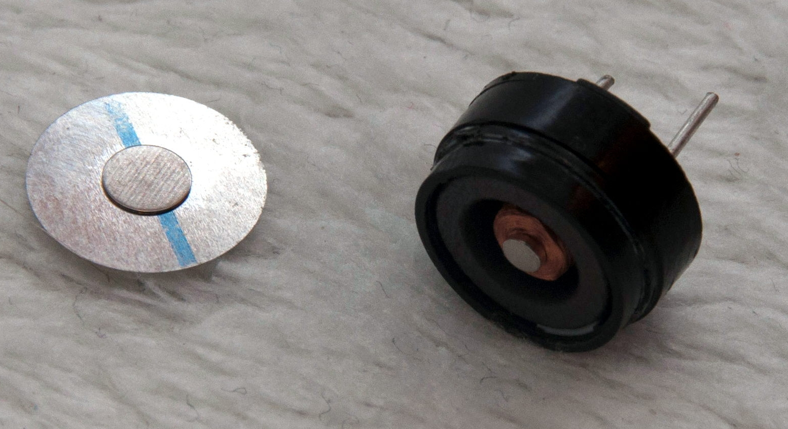
A “piezo” buzzer that was assumed to have no significant magnetic field, but in fact contained a magnet.
The other interesting problems were less straightforward and were related to the digital compass, or magnetometer. The first problem was that the piezo buzzers [Jan] sourced contained no actual piezo elements. They contained magnets – which interfered with the operation of the digital compass. After solving that, still more compass problems arose. When testing the final units in the field, the compass readings were not as expected and [Jan] had no idea why.
After careful troubleshooting, the culprit was found: the AA cells on the other side of the circuit board. Every AA cell has a faint (and slightly different) magnetic field, and the proximity and placement of the cells with respect to the magnetometer was causing the deviation. Happily, the fix was simple once the problem was understood: calibrate the compass every time new batteries are inserted.
If you’re interested in the Navigation Thing, check out the github repository. And on the topic of actual piezoelectric devices, piezos are implemented in a variety of clever ways. There are even piezo transformers and piezo vacuum pumps.
Well all know cellular automata from Conway’s Game of Life which simulates cellular evolution using rules based on the state of all eight adjacent cells. [Gavin] has been having fun playing with elementary cellular automata in his spare time. Unlike Conway’s Game, elementary automata uses just the left and right neighbors of a cell to determine the next cell ahead in the row. Despite this comparative simplicity, some really complex patterns emerge, including a Turing-complete one.
[Gavin] started off doing the calculations by hand for fun. He made some nice worksheets for this. As we can easily imagine, doing the calculations by hand got boring fast. It wasn’t long before his thoughts turned to automating his cellular automata. So, he put together an automatic cellular automator. (We admit, we are having a bit of fun with this.)
This could have been a quick software project but half the fun is seeing the simulations on a purpose-built ecosystem. The files to build the device are hosted on Thingiverse. Like other cellular automata projects, it uses LED matrices to display the data. An Arduino acts as the brain and some really cool retro switches from the world’s most ridiculously organized electronics collection finish the look of the project.
To use, enter the starting condition with the switches at the bottom. The code on the Arduino then computes and displays the pattern on the matrix. Pretty cool and way faster than doing it by hand.
This is a guest post by the EasyEDA team. I would like to thank EasyEDA for providing this tutorial for everyone to enjoy. All information within this post was provided by EasyEDA.
Description
None of us could deny the fact that we would love with to play with LED’s and lighting stuff. I love to play with LED’s and create attractive lighting effects. This project was a result of such an attempt where I created a stunning RGB light effect using the popular development platform Arduino Nano. Let’s see the circuit, code and instruction on building this project:
No libraries are required for this project. The Arduino IDE can be downloaded from the Arduino website. Here is the download link.
ARDUINO CODE:
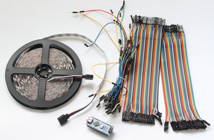
Preparing the LED strips
Cut down the LED strips into 10 single pieces. Make sure you cut them into equal halves and make sure that only the copper conduction plate in the strip is cut. Making a wrong cut disrupts the electrical conductivity between the LED’s. After cutting down into separate strips, you will need to connect each strip using a Dupont wire connectors.
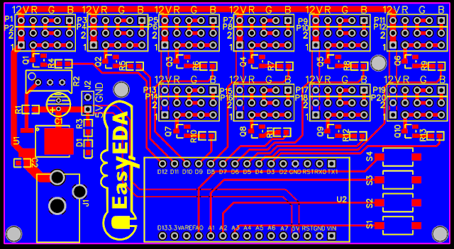
I have made a custom control board that incorporates an Arduino Nano. The control board is used to boost the incoming signal from Arduino and lights up the corresponding LED strips.
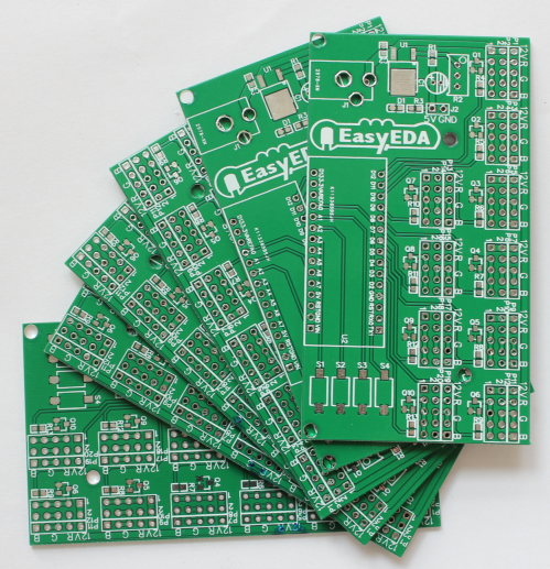
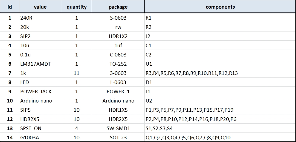
I used a free Online circuit and PCB designing platform called EasyEDA to develop my control board. It is pretty easy to use especially because of the large library of parts to choose from. Once the design is complete, you have the option to order it through EasyEDA. They offers great prices on custom PCB manufacturing. I have added 10 connection points for 10 LED strips. Each RGB LED strip is controlled by one of the Arduino Nano digital pins.. Transistors Q1,Q2,Q3….Q10 act as a switch for these LED strips for controlling 12V strips via a 5V signal from the Arduino. And switches S1,S2..S4 were added to be able to select the effect on the strip. The schematic can be seen below:
Schematic
You can access the actual EasyEDA schematic by clicking on the image below:
After completing the PCB design, you can click on the Fabrication icon.
You will then have access to the PCB order page which will allow you to download your PCB Gerber files that can be sent to any manufacturer. However it is a lot easier (and cheaper) to order it directly from EasyEDA. Here you can select:
the number of PCBs you want to order
the number of copper layers you need
the PCB thickness
copper weight
and even the PCB color
After you’ve selected all of the options, click “Save to Cart” and complete you order. You will then get your PCBs shipped a few days later.
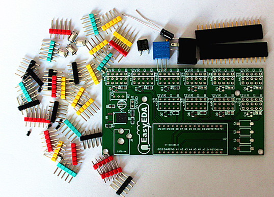
Connect the LED strips through the connection points in the board. Make sure that you connect these correctly (push the connectors all the way onto the pin), because the chances of a short increase significantly with the number of wires connected. Once all the connections are done all that left is to install your Arduino Nano (pre-programmed with the Arduino code above), and to power the PCB with a 12V power supply.


