Posts with «led» label

Super simple controller for Motorcycle LED lights

For automobiles, especially motorcycles, auxiliary lighting that augments the headlights can be quite useful, particularly when you need to drive/ride through foggy conditions and poorly lit or unlit roads and dirt tracks. Most primary lighting on vehicles still relies on tungsten filament lamps which have very poor efficiency. The availability of cheap, high-efficiency LED modules helps add additional lighting to the vehicle without adding a lot of burden on the electrical supply. If you want to add brightness control, you need to either buy a dimmer module, or roll your own. [PatH] from WhiskeyTangoHotel choose the latter route, and built a super simple LED controller for his KLR650 bike.

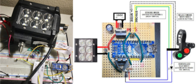
He chose a commonly available 18 W light bar module containing six 3 W LEDs. He then decided to build a microcontroller based dimmer to offer 33%, 50% and 100% intensities. And since more code wasn’t going to cost him anything extra, he added breathing and strobe modes. The hardware is as barebones as possible, consisting of an Arduino Nano, linear regulator, power MOSFET and control switch, with a few discretes thrown in. The handlebar mounted control switch is a generic motorcycle accessory that has two push buttons (horn, headlight) and a slide switch (turn indicators). One cycles through the various brightness modes on the pushbutton, while the slide switch activates the Strobe function. A status indicator LED is wired up to the Nano and installed on the handlebar control switch. It provides coded flashes to indicate the selected mode.

It’s a pity that the “breathing” effect is covered under a patent, at least for the next couple of years, so be careful if you plan to use that mode while on the road. And the Strobe mode — please don’t use it — like, Ever. It’s possible to induce a seizure which won’t be nice for everyone involved. Unless you are in a dire emergency and need to attract someone’s attention for help.


Filed under: led hacks
Hack a Day 09 Sep 09:00

Spice Up Your Bench With 3D Printed Dancing Springs

Not all projects are made equal. Some are designed to solve a problem while others are just for fun. Entering the ranks of the most useless machines is a project by [Vladimir Mariano] who created the 3D Printed Dancing Springs. It is a step up from 3D printing a custom slinky and will make a fine edition to any maker bench.

The project uses 3D printed coils made of transparent material that is mounted atop geared platforms and attached to a fixed frame. The gears are driven by a servo motor. The motor rotates the gears and the result is a distortion in the spring. This distortion is what the dancing is all about. To add to the effect, [Vladimir Mariano] uses RGB LEDs controlled by an ATmega32u4.

You can’t dance without music. So [Vladimir] added a MEMs microphone to pick up noise levels which are used to control the servo and lights. The code, STL files and build instructions are available on the website for you to follow along. If lights and sound are your things, you must check out the LED Illuminated Isomorphic Keyboard from the past.


Filed under: musical hacks
Hack a Day 30 Jul 06:00
arduino  diy  led  musical hacks  neopixel  slinky  sound  toy  

This Model Parisian Building Is Actually a Binary Clock

Four creators fixed an Arduino powered LED binary clock inside a wooden model of a Parisian building to create a fancy addition to any home.

Read more on MAKE

The post This Model Parisian Building Is Actually a Binary Clock appeared first on Make: DIY Projects and Ideas for Makers.

Ever hear of the Ford Cylon?

OK, we haven’t heard of a Ford Cylon either. However, there is now a Mustang Cobra out there that has been given a famous Cylon characteristic. [Monta Elkins] picked himself up an aftermarket third brake light assembly, hacked it, and installed it on said Mustang.

The brake light assembly contains 12 LEDs, which unfortunately, are not individually addressable. Additionally, by the looks of it, the brake light housing was not meant to be opened up. That didn’t get [Monta] down though. There’s more than one way to skin a cat, but he chose to use a hot knife to open the assembly, which worked quite well. A rotary cutter tool was used to cut the traces between the LEDs allowing them to be individually controlled with an Arduino. A Bluetooth module allows him to control the new brake light from his smartphone. There are different modes (including a special mode that he shows off at the end of the video) that can be selected via a Bluetooth Terminal app.

There is no schematic or code link in the video itself or the description, but [Monta] did hit the high points. Therefore, it shouldn’t be too hard to replicate.

This isn’t the first brake light hack we’ve featured. This one goes way beyond just animated lightsThis one requires no programming. Rather wear your brake light? We’ve got your back(pack).


Filed under: car hacks, led hacks
Hack a Day 26 May 03:00

Pi Time – A Fabric RGB Arduino Clock

Pi Time is a psychedelic clock made out of fabric and Neopixels, controlled by an Arduino UNO. The clock started out as a quilted Pi symbol. [Chris and Jessica] wanted to make something more around the Pi and added some RGB lights. At the same time, they wanted to make something useful, that’s when they decided to make a clock using Neopixels.

Neopixels, or WS2812Bs, are addressable RGB LEDs , which can be controlled individually by a microcontroller, in this case, an Arduino. The fabric was quilted with a spiral of numbers (3.1415926535…) and the actual reading of the time is not how you are used to. To read the clock you have to recall the visible color spectrum or the rainbow colors, from red to violet. The rainbow starts at the beginning of the symbol Pi in the center, so the hours will be either red, yellow, or orange, depending on how many digits are needed to tell the time. For example, when it is 5:09, the 5 is red, and the 9 is yellow. When it’s 5:10, the 5 is orange, the first minute (1) is teal, and the second (0) is violet. The pi symbol flashes every other second.

There are simpler and more complicated ways to perform the simple task of figuring out what time it is…

We are not sure if the digits are lighted up according to their first appearance in the Pi sequence or are just random as the video only shows the trippy LEDs, but the effect is pretty nice:


Filed under: Arduino Hacks, led hacks
Hack a Day 17 Apr 03:00

Maker Spotlight: Cynthia Cho

Who on Earth Needs a Ninja Timer?

John Edgar Park builds a giant 7-segment display timer for a Ninja obstacle course.

Read more on MAKE

The post Who on Earth Needs a Ninja Timer? appeared first on Make: DIY Projects and Ideas for Makers.

Prextron CHAIN BLOCKS - Arduino Nano controlled Ultrasonic sensor that switches a motor wirelessly using 433MHz RF modules and a relay board.


Description

In this tutorial, I will be evaluating Prextron CHAIN blocks – a new system that allows you to connect your sensors and actuators to an Arduino NANO using clever 3D-printed prototyping boards that can be stacked sideways. This very modular system makes it easy to connect, disconnect and replace project components, and eliminate the “rats nest of wires” common to many advanced Arduino projects. CHAIN BLOCKS are open, which means that you can incorporate any of your sensors or actuators to these prototyping boards, and you can decide which specific pin on Arduino you plan to use. The CHAIN BLOCK connections prevent or reduce common connection mistakes, which make them ideal for class-room projects and learning activities.

I am going to set up a project to put these CHAIN BLOCKs to the test:
When I place my hand in-front of an Ultrasonic sensor, the Arduino will transmit a signal wirelessly to another Arduino, and consequently turn on a motor.


Parts Required:

You need the following Prextron Chain Blocks


Please note: You may need to solder the module wires to the CHAIN BLOCK protoboard.


Arduino Libraries and IDE

This project does not use any libraries. However, you will need to upload Arduino code to the Arduino. For this you will need the Arduino IDE which can be obtained from the official Arduino website:
https://www.arduino.cc/en/main/software


ARDUINO CODE: RF Transmitter


ARDUINO CODE: RF Receiver


Fritzing diagrams for Transmitter


Fritzing diagrams for Receiver


Concluding comments

The purpose of this project was to evaluate Prextron CHAIN BLOCKs and put them to the test. Here is what I thought of CHAIN BLOCKS at the time of evaluation. Some of my points mentioned below may no longer apply to the current product. It may have evolved / improved since then. So please take that into consideration


What I liked about Chain Blocks

  • The design is simple, the product is simple.
  • Once the Chain Blocks were all assembled, they were very easy to connect to each other.
  • I can really see the benefit of Chain Blocks in a teaching environment, because it simplifies the connection process, and reduces connection mixups.
  • It was good to see that the blocks come in different colours, which means that you can set up different colour schemes for different types of modules.
  • You can incorporate pretty much any sensor or Actuator into the Chain block which is very appealing.
  • You also have the flexibility of choosing which pins you plan to use on the Arduino.
  • Projects look a lot neater, because you no longer have the rats nest of wires.
  • The Blocks lock into each other which means that they are much easier to transport/carry.


What I did not like about Chain Blocks

  • In most cases, the Chain Block protoboard lanes were not numbered, which increased the chances of making mistakes when soldering
  • The need to solder modules to the protoboard, may be a discouragement for some people.
  • I would have liked a choice of different size Chain blocks. Some of the sensors did not fit nicely into the Square blocks.
  • Prextron really need to work on their website if they plan to get serious with this product: Webpage has incomplete functionality or irrelevant links etc etc.


Thank you very much to Prextron for providing the CHAIN BLOCKS used in this tutorial, and allowing me to try out their product. If you are interested in trying them yourself, then make sure to visit them at:


If you like this page, please do me a favour and show your appreciation :

 
Visit my ArduinoBasics Google + page.
Follow me on Twitter by looking for ScottC @ArduinoBasics.
I can also be found on Pinterest and Instagram.
Have a look at my videos on my YouTube channel.


The Best of Both Worlds: Arduino + 555 Should Confuse Commenters

Hardly a week goes by that some Hackaday post doesn’t elicit one of the following comments:

That’s stupid! Why use an Arduino when you could do the same thing with a 555?

And:

That’s stupid! Why use a bunch of parts when you can use an Arduino?

However, we rarely see those two comments on the same post. Until now. [ZHut] managed to bring these two worlds together by presenting how to make an Arduino blink an LED in conjunction with a 555 timer. We know, we know. It is hard to decide how to comment about this. You can consider it while you watch the video, below.

On the plus side, there probably is a use case for this. The LED will blink with absolutely no intervention from the Arduino. You could put the Arduino in deep sleep, if you wanted to and that LED will still blink. With a little work, you could probably adapt this idea to any number of circuits out of the 555 playbook, like a PWM generator, for example.

There’s almost nothing a 555 can’t do. If you want to see what’s under its expressionless face, this teardown is an interesting read. We just hope the comment section doesn’t overload like a Star Trek computer being asked by Captain Kirk to compute every digit of pi.


Filed under: Arduino Hacks
Hack a Day 03 Mar 03:00