Posts with «led» label

Blinky LED Bike Bag

Bicycle riders can never be too visible: the more visible you are, the less chance there is someone will hit you. That’s the idea behind the Arduibag, a neat open-source project from [Michaël D’Auria] and [Stéphane De Graeve]. The project combines a joystick that mounts on the handlebars with a dot matrix LED display in a backpack. By moving the joystick, the user can indicate things such as that they are turning, stopping, say thank you or show a hazard triangle to warn of an accident.

The whole project is built from simple components, such as an Adafruit LED matrix and a Bluno (an Arduino-compatible board with built-in Bluetooth 4.0) combined with a big battery that drives the LED matrix. This connects to the joystick, which is in a 3D printed case that clips onto the handlebars for easy use. It looks like a fairly simple build, with the larger components being mounted on a board that fits into the backpack and holds everything in place. You then add a clear plastic cover to part of the backpack over the LED matrix, and you are ready to hit the road, hopefully without actually hitting the road.

Like any good project, [Michaël] and [Stéphane] aren’t finished with it yet: they are also looking for ways to improve it. In particular, they want to reduce the number of batteries, as there is currently a large battery that drives the display and another smaller one that drives the Arduino.


Filed under: Arduino Hacks, wearable hacks
Hack a Day 13 Mar 18:00

Banish Dangerous Shadows Under Kitchen Cabinets

[nebulous] has a lot of problems with his kitchen cabinets. Aside from a noted lack of micro-controllers, he was especially suspicious of the dark spaces under them. Anything could be hiding there.

The core of the project is a $10 Arduino-compatible esp8266 board from digistump. The board is powered by the five volt regulator of an L298N motor driver module hooked to a power-supply. All this controls a set-of LED strips adhered to the underside of the cabinets with the traditionally bad adhesive strips with which they come standard. We can predict an hour spent bent awkwardly cursing at them, a hot-glue gun in one hand, in [nebulous]’s future. The whole set-up is housed in a SparkFun cardboard box above the microwave. You can barely tell it’s not a commercial product.

We’re not certain if we like a future where even our cabinetry has an IP address. However, this is a good weekend project that could make all our cabinetry brighter, safer, and more connected.


Filed under: home hacks, led hacks

Go Behind the Scenes of Installing an Interactive LED Art Exhibit

Nick Squires details his time spent using his maker skills to produce an interactive art installation and performance.

Read more on MAKE

The post Go Behind the Scenes of Installing an Interactive LED Art Exhibit appeared first on Make: DIY Projects and Ideas for Makers.

Visualizing “data visualization” with Leds and bubbles

“Data transparency” is a project by Jiayu Liu, a designer and media artist, interested in physical data visualisation and interactive code. The installation runs on Arduino Mega: when the microphone senses a person’s blow, it transforms it in a Led animation and then activates the bubble machine for 8 seconds. The project is not aiming to visualize any specific data but “data visualization” itself:

In my point of view, data is not dissimilar to a conclusion of our past, and we need it for our future. When we see a data from a computer, it is something that has already happened. We use intelligent methods of computing science to analyze the data so that to predict the future. We are living in a world of data, and data is like a language objectively describing our past. In this work, I take more attention on rethinking and recalibrating the role of data in our lives, and the relationship between the virtual world we build as a main method of data storing, analyzing and visualization and ourselves.

Also, I am thinking of that it is better to make sense of the role of data visualization before really visualizing it. Finally, I found a good perspective to see how data connects with our lives, which is Time.
Therefore, the project is not aiming to visualize any specific data but what I am trying to visualize is the “data visualization” itself. I would like to bring a new experience to the viewer in different space. So I want to create a interesting play space and bubble game to the viewer . Let them have a really funny and relaxing experience.

Take a look at the “making of” video below to see it in action:

The Newest Graphing Calculator Game

Certainly everyone remembers passing time in a boring high school class playing games on a graphing calculator. Whether it was a Mario-esque game, Tetris, or BlockDude, there are plenty of games out there for pretty much all of the graphing calculators that exist. [Christopher], [Tim], and their colleagues from Cemetech took their calculator game a little bit farther than we did, and built something that’ll almost surely disrupt whatever class you’re attempting to pay attention in: They built a graphing calculator whac-a-mole game.

This game isn’t the standard whac-a-mole game, though, and it isn’t played on the calculator’s screen. Instead of phyiscal “moles” the game uses LEDs and light sensors enclosed in a box to emulate the function of the moles. In order to whack a mole, the player only needs to interrupt the light beam which can be done with any physical object. The team made extensive use of the ArTICL library which allows graphing calculators to interface with microcontrollers like the MSP432 that they used, and drove the whole thing with a classic TI-84.

This project is a fun way to show what can be done with a graphing calculator and embedded electronics, and it was a big hit at this past year’s World Maker Faire. Calculators are versatile in other ways as well. We’ve seen them built with open hardware and free software, And we’ve even seen them get their own Wi-Fi.


Filed under: handhelds hacks

Cricket Scoreboard is a Big Win for Novice Hackers

The game of cricket boggles most Americans in the same way our football perplexes the rest of the world. We won’t even pretend to understand what a “wicket” or an “over” is, but apparently it’s important enough to keep track of that so an English cricket club decided to build their own electronic scoreboard for their – pitch? Field? Help us out here.

This scoreboard build was undertaken by what team member [Ian] refers to as some “middle-aged blokes from Gloucestershire” with no previous electronics experience. That’s tough enough to deal with, but add to it virtually no budget, a huge physical size for the board, exposure to the elements, and a publicly visible project where failure would be embarrassingly obvious, and this was indeed an intimidating project to even consider. Yet despite the handicaps, they came up with a great rig, with a laser-cut acrylic cover for a professional look. A Raspberry Pi runs the LED segments and allows WiFi connections from a laptop or phone in the stands. They’ve even recently upgraded to solar power for the system.

And we’ll toot our own horn here, since this build was inspired at least in part by a Hackaday post. The builders have a long list of other links that inspired or instructed them, and we think that says something powerful about the hacker community that we’ve all been building – a group with no previous experience manages a major build with the guidance of seasoned hackers. That’s something to feel good about.


Filed under: misc hacks, Raspberry Pi
Hack a Day 24 Jan 12:01

Create Big Music Mashups on This Enormous MIDI Sequencer Board

A picture might be worth a thousand words, but for an interactive sound work called GRIDI a picture is worth infinite midi loops!

Read more on MAKE

The post Create Big Music Mashups on This Enormous MIDI Sequencer Board appeared first on Make: DIY Projects, How-Tos, Electronics, Crafts and Ideas for Makers.

How to Sequence LEDs to Music: A Tutorial by Freaklabs

Akiba of Freaklabs helped design sequenced lighting like those used in the Wrecking Crew Orchestra shows

Read more on MAKE

The post How to Sequence LEDs to Music: A Tutorial by Freaklabs appeared first on Make: DIY Projects, How-Tos, Electronics, Crafts and Ideas for Makers.

Arduino LED Light Box

Description

Long straight lines of LED luminescence is nice, but sometimes you may want to light up something that has an unusual shape, or is not so linear. This is where the 12mm diffused flat digital RGB LED Pixels can come into play. This cool strand of 25 NeoPixels fit nicely into 12mm pre-drilled holes of any material you like.

This tutorial is dedicated to making a LED Light Box. I wanted the box to be equally as interesting during the day as it was at night. If you decide you make your own, feel free to be as creative as you want !! However, if you lack artistic acumen, you may need to source a minion or two.


Arduino Libraries and IDE

Before you start to hook up any components, upload the following sketch to the Arduino microcontroller. I am assuming that you already have the Arduino IDE installed on your computer. If not, the IDE can be downloaded from here.

The FastLED library is useful for simplifying the code for programming the NeoPixels. The latest "FastLED library" can be downloaded from here. I used FastLED library version 3.0.3 in this project.

If you have a different LED strip or your NeoPixels have a different chipset, make sure to change the relevant lines of code to accomodate your hardware. I would suggest you try out a few of the FastLED library examples before using the code below, so that you become more familiar with the library, and will be better equipped to make the necessary changes.

If you have a single strand of 25 Neopixels with the WS8201 chipset, then you will not have to make any modification below.


ARDUINO CODE:

Arduino Code Description

The code above will generate a randomised raindrop pattern on the NeoPixel LED Light box, however I have written code for a few more LED animations. These animations were written specifically for this light-box setup. In other words, once you have hooked everything up, you will be able to upload these other LED animations to the Arduino board without any further modification to the hardware/wiring, and yet experience a totally different light effect. You can find the code for the other animation effects by clicking on the links below:

  1. Breathing effect
  2. Ripple effect
  3. Clock effect
  4. Rotation effect
  5. Sweep effect
  6. Spiral effect
  7. Lightning effect
  8. Paparazzi in the Rain effect

Hooking it up:

Power requirements

Each Neopixel LED can draw up to 60 milliamps at maximum brightness (white). ie. 20 mA for each colour (red, green and blue). Therefore you should not try to power the LED strand directly from the Arduino, because the strand will draw too much current and damage the microcontroller(and possibly your USB port too). The LED strand will therefore need to be powered by a separate power supply. The power supply must supply the correct voltage (5V DC) and must also be able to supply sufficient current (1.5A or greater per strand of 25 LEDs).

Excessive voltage will damage or destroy your Neopixel strand. The LEDs will only draw as much current as they need, however your power supply must provide at least 1.5A or greater for each strand. If you chain two strands together, you will need a 5V 3A power supply.

Neopixel strand connection

There are 25 Neopixel LEDs per strand. Four of the wires at each end of the strand are terminated with a JST connector. The red wire is for power (VCC), blue wire for ground (GND), yellow wire is for Data, and green wire for Clock. A spare red wire (VCC) and a spare blue wire (GND) are attached to the ends of each strand for convenience, however, I did not use either. Please double check the colour of your wires... they may be different.

If you want to attach the LED strand to a breadboard, you can cut the JST connector off and use the Neopixel strand wires. Alternatively, if you would prefer to preserve the JST connector, you can simply insert jumper wires (or some male header pins) into the JST connector, and then plug them into the breadboard as required.

Each neopixel LED is individually controllable using two pins on your Arduino. The strand is directional. i.e. There is an INPUT side and an OUTPUT side. The strand should be connected such that wires from the microcontroller are attached to the INPUT side of the first neopixel. The arrows on each LED show the direction of data flow from INPUT to OUTPUT. The arrow on the first NeoPixel should be pointing towards the second NeoPixel, NOT towards the breadboard.

Other considerations

As a precaution, you should use a large capacitor across the + and - terminals of the power supply to prevent the initial onrush of current from damaging the Neopixels. I used a 4700uF 16V Electrolytic capacitor for this purpose. According to Adafruit, a 1000uF 6.3V capacitor (or higher) will also do the trick. You may also want to consider a 330 ohm resistor between the Arduino Digital pin and the strand's DATA pin.

If you want to power the Arduino using the regulated 5V external power supply. Disconnect the USB cable from the Arduino, and then connect the positive terminal of the power supply to the 5V pin on the Arduino. Be warned however, that excess voltage at this pin could damage your Arduino, because the 5V regulator will be bypassed.
 
Providing the USB cable is NOT connected to the Arduino, it should now be safe to plug the power supply into the wall. This setup will allow you to power the Neopixel strand and the Arduino using the same power supply.
 
WARNING: Never change any connections while the circuit is powered.

For more information about these NeoPixel strands, you may want to visit the Adafruit site. Adafruit was the source for most of these NeoPixel Strand precautions.


Fritzing diagram

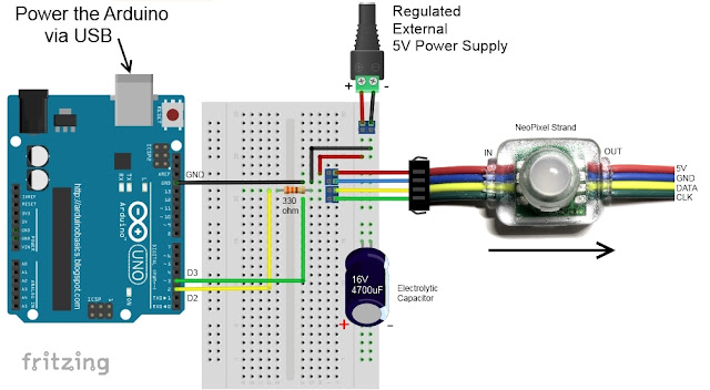
The following diagram demonstrates how to connect the NeoPixel Strand to the Arduino and to the External 5V power supply.


This diagram was created using Fritzing


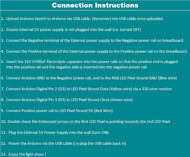
Connection Instructions

These instructions will help to guide you through the process of connecting your NeoPixel strand to the Arduino, and to the external power supply. The instructions assume that you will be powering the Arduino via a USB cable.


LightBox assembly

You will need to drill a 12mm hole into the craft timber box for each LED on the strand. It is worth taking the time to make accurate measurements before drilling the holes.
 
I made 12 holes for the outside circle pattern (12cm diameter), 6 holes for the inside circle pattern (8cm diameter), and a hole in the centre. I also made two holes at the front of the box, two on the left side, and two on the right side. I made one last hole at the back of the box for the 2.1mm DC power line socket.
 
Therefore you should have a total of 26 holes in the box. 25 of the holes are for the Neopixel LEDs and one for the external power supply socket.

The lid of the box is about 19.5cm x 14.5cm long, which makes for a very tight squeeze. Probably too tight, because you have to account for the inner dimensions of the box. The inside of the box is used to house the Arduino, breadboard, the chipset side of the LEDs and cables/components. The inner dimensions of the box are 18cm x 13cm. Therefore, the housing for the LED chipset PCB (1.8cm x 2.5cm) prevented the box from closing. I used a Dremel to carve out the space required to close the lid.

Each LED is approximately 8cm apart on the strand, however, if you are really keen, you could cut the wires and extend them to any distance you require. But keep in mind that each LED is mounted on a small PCB (with a WS2801 chipset).You will therefore need to leave a minimum of 2cm between each 12mm hole to accomodate the size of the PCB+LED. If you plan carefully, you can probably squeeze a couple of LEDs within a distance of 1cm... but I would recommend that you give yourself a bit more room, because the PCBs are not square, and there is a good chance that you will have to start all over again.

In hindsight, I could have made the circle patterns a bit smaller, however I don't know if I could have packed these LEDs any closer. The diameter of the inner circle pattern must be at least 2cm smaller than the outer circle pattern. So I think "a bigger box" would have been the best option.

Once all of the holes have been drilled, paint and decorate the box to suit your style.

When the paint is dry, insert the LEDs into the drilled holes in number order.
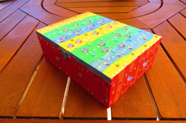
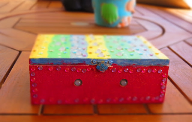
You can see the end result below.


Project Pictures

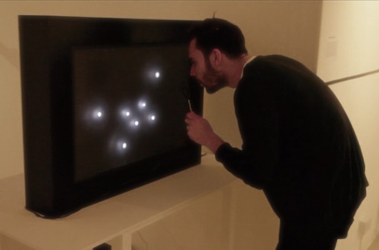
These pictures show the Light box after it has been drilled and painted. The LEDs have been inserted into their respective holes, and all wires + Arduino + breadboard are hidden within the box.


Concluding comments

Once you start writing LED animations for the NeoPixel Lightbox, it is very hard to stop. The colour combinations


If you like this page, please do me a favour and show your appreciation :

 
Visit my ArduinoBasics Google + page.
Follow me on Twitter by looking for ScottC @ArduinoBasics.
I can also be found on Pinterest and Instagram.
Have a look at my videos on my YouTube channel.


This project would not have been possible without OpenLab's collaborative effort.
Please visit their site for more cool projects.


However, if you do not have a google profile...
Feel free to share this page with your friends in any way you see fit.

Arduino LED Light Box

Description

Long straight lines of LED luminescence is nice, but sometimes you may want to light up something that has an unusual shape, or is not so linear. This is where the 12mm diffused flat digital RGB LED Pixels can come into play. This cool strand of 25 RGB LED pixels fit nicely into 12mm pre-drilled holes of any material you like.

This tutorial is dedicated to making a LED Light Box. I wanted the box to be equally as interesting during the day as it was at night. If you decide you make your own, feel free to be as creative as you want !! However, if you lack artistic acumen, you may need to source a minion or two.


Arduino Libraries and IDE

Before you start to hook up any components, upload the following sketch to the Arduino microcontroller. I am assuming that you already have the Arduino IDE installed on your computer. If not, the IDE can be downloaded from here.

The FastLED library is useful for simplifying the code for programming the RGB LED pixels. The latest "FastLED library" can be downloaded from here. I used FastLED library version 3.0.3 in this project.

If you have a different LED strip or your RGB LED pixels have a different chipset, make sure to change the relevant lines of code to accomodate your hardware. I would suggest you try out a few of the FastLED library examples before using the code below, so that you become more familiar with the library, and will be better equipped to make the necessary changes.

If you have a single strand of 25 RGB LED pixels with the WS8201 chipset, then you will not have to make any modification below.


ARDUINO CODE:

Arduino Code Description

The code above will generate a randomised raindrop pattern on the Arduino LED Light box, however I have written code for a few more LED animations. These animations were written specifically for this light-box setup. In other words, once you have hooked everything up, you will be able to upload these other LED animations to the Arduino board without any further modification to the hardware/wiring, and yet experience a totally different light effect. You can find the code for the other animation effects by clicking on the links below:

  1. Breathing effect
  2. Ripple effect
  3. Clock effect
  4. Rotation effect
  5. Sweep effect
  6. Spiral effect
  7. Lightning effect
  8. Paparazzi in the Rain effect

Hooking it up:

Power requirements

Each LED pixel can draw up to 60 milliamps at maximum brightness (white). ie. 20 mA for each colour (red, green and blue). Therefore you should not try to power the LED strand directly from the Arduino, because the strand will draw too much current and damage the microcontroller(and possibly your USB port too). The LED strand will therefore need to be powered by a separate power supply. The power supply must supply the correct voltage (5V DC) and must also be able to supply sufficient current (1.5A or greater per strand of 25 LEDs).

Excessive voltage will damage or destroy your LED pixel strand. The LEDs will only draw as much current as they need, however your power supply must provide at least 1.5A or greater for each strand. If you chain two strands together, you will need a 5V 3A power supply.

RGB LED pixel strand connection

There are 25 LED pixels per strand. Four of the wires at each end of the strand are terminated with a JST connector. The red wire is for power (VCC), blue wire for ground (GND), yellow wire is for Data, and green wire for Clock. A spare red wire (VCC) and a spare blue wire (GND) are attached to the ends of each strand for convenience, however, I did not use either. Please double check the colour of your wires... they may be different.

If you want to attach the LED strand to a breadboard, you can cut the JST connector off and use the LED pixel strand wires. Alternatively, if you would prefer to preserve the JST connector, you can simply insert jumper wires (or some male header pins) into the JST connector, and then plug them into the breadboard as required.

Each LED pixel is individually controllable using two pins on your Arduino. The strand is directional. i.e. There is an INPUT side and an OUTPUT side. The strand should be connected such that wires from the microcontroller are attached to the INPUT side of the first LED pixel. The arrows on each LED show the direction of data flow from INPUT to OUTPUT. The arrow on the first LED pixel should be pointing towards the second LED pixel, NOT towards the breadboard.

Other considerations

As a precaution, you should use a large capacitor across the + and - terminals of the power supply to prevent the initial onrush of current from damaging the RGB LED pixels. I used a 4700uF 16V Electrolytic capacitor for this purpose. According to Adafruit, a 1000uF 6.3V capacitor (or higher) will also do the trick. You may also want to consider a 330 ohm resistor between the Arduino Digital pin and the strand's DATA pin.

If you want to power the Arduino using the regulated 5V external power supply. Disconnect the USB cable from the Arduino, and then connect the positive terminal of the power supply to the 5V pin on the Arduino. Be warned however, that excess voltage at this pin could damage your Arduino, because the 5V regulator will be bypassed.
 
Providing the USB cable is NOT connected to the Arduino, it should now be safe to plug the power supply into the wall. This setup will allow you to power the RGB LED pixel strand and the Arduino using the same power supply.
 
WARNING: Never change any connections while the circuit is powered.

For more information about these RGB LED pixel strands, you may want to visit the Adafruit site. Adafruit was the source for most of these RGB LED pixel Strand precautions.


Fritzing diagram

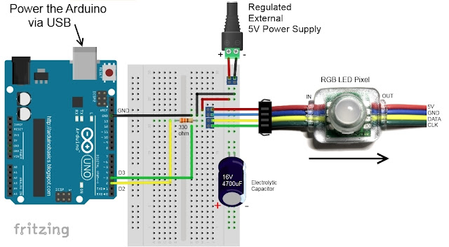
The following diagram demonstrates how to connect the RGB LED pixel Strand to the Arduino and to the External 5V power supply.


This diagram was created using Fritzing


Connection Instructions

These instructions will help to guide you through the process of connecting your RGB LED pixel strand to the Arduino, and to the external power supply. The instructions assume that you will be powering the Arduino via a USB cable.


LightBox assembly

You will need to drill a 12mm hole into the craft timber box for each LED on the strand. It is worth taking the time to make accurate measurements before drilling the holes.
 
I made 12 holes for the outside circle pattern (12cm diameter), 6 holes for the inside circle pattern (8cm diameter), and a hole in the centre. I also made two holes at the front of the box, two on the left side, and two on the right side. I made one last hole at the back of the box for the 2.1mm DC power line socket.
 
Therefore you should have a total of 26 holes in the box. 25 of the holes are for the RGB LED pixel LEDs and one for the external power supply socket.
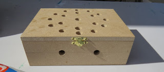
The lid of the box is about 19.5cm x 14.5cm long, which makes for a very tight squeeze. Probably too tight, because you have to account for the inner dimensions of the box. The inside of the box is used to house the Arduino, breadboard, the chipset side of the LEDs and cables/components. The inner dimensions of the box are 18cm x 13cm. Therefore, the housing for the LED chipset PCB (1.8cm x 2.5cm) prevented the box from closing. I used a Dremel to carve out the space required to close the lid.

Each LED is approximately 8cm apart on the strand, however, if you are really keen, you could cut the wires and extend them to any distance you require. But keep in mind that each LED is mounted on a small PCB (with a WS2801 chipset).You will therefore need to leave a minimum of 2cm between each 12mm hole to accomodate the size of the PCB+LED. If you plan carefully, you can probably squeeze a couple of LEDs within a distance of 1cm... but I would recommend that you give yourself a bit more room, because the PCBs are not square, and there is a good chance that you will have to start all over again.

In hindsight, I could have made the circle patterns a bit smaller, however I don't know if I could have packed these LEDs any closer. The diameter of the inner circle pattern must be at least 2cm smaller than the outer circle pattern. So I think "a bigger box" would have been the best option.

Once all of the holes have been drilled, paint and decorate the box to suit your style.

When the paint is dry, insert the LEDs into the drilled holes in number order.
You can see the end result below.


Project Pictures

These pictures show the Light box after it has been drilled and painted. The LEDs have been inserted into their respective holes, and all wires + Arduino + breadboard are hidden within the box.



Concluding comments

Once you start writing LED animations for the RGB LED pixel Lightbox, it is very hard to stop. The colour combinations


If you like this page, please do me a favour and show your appreciation :

 
Visit my ArduinoBasics Google + page.
Follow me on Twitter by looking for ScottC @ArduinoBasics.
I can also be found on Pinterest and Instagram.
Have a look at my videos on my YouTube channel.


This project would not have been possible without OpenLab's collaborative effort.
Please visit their site for more cool projects.


However, if you do not have a google profile...
Feel free to share this page with your friends in any way you see fit.