Posts with «led» label

New Project: 3D Print a Supersized Seven-Segment Clock

Building your own clock is practically a rite of passage as a Maker. 3D-print this Arduino-based desktop clock with a jumbo seven-segment LED display that glows from within.

Read more on MAKE

The post 3D Print a Supersized Seven-Segment Clock appeared first on Make: DIY Projects, How-Tos, Electronics, Crafts and Ideas for Makers.

Experimenting with Arduino and IKEA DIODER LED Strips

Introduction

A few weeks ago I found a DIODER LED strip set from a long-ago trek to IKEA, and considered that something could be done with it.  So in this article you can see how easy it is to control the LEDs using an Arduino or compatible board with ease… opening it up to all sorts of possibilities.

This is not the most original project – however things have been pretty quiet around here, so I thought it was time to share something new with you. Furthermore the DIODER control PCB has changed, so this will be relevant to new purchases. Nevertheless, let’s get on with it.

So what is DIODER anyhow? 

As you can see in the image below, the DIODER pack includes four RGB LED units each with nine RGB LEDs per unit. A controller box allows power and colour choice, a distribution box connects between the controller box and the LED strips, and the whole thing is powered by a 12V DC plugpack:

The following is a quick video showing the DIODER in action as devised by IKEA:


Thankfully the plugpack keeps us away from mains voltages, and includes a long detachable cable which connects to the LED strip distribution box. The first thought was to investigate the controller, and you can open it with a standard screwdriver. Carefully pry away the long-side, as two clips on each side hold it together…


… which reveals the PCB. Nothing too exciting here – you can see the potentiometer used for changing the lighting effects, power and range buttons and so on:

Our DIODER has the updated PCB with the Chinese market microcontroller. If you have an older DIODER with a Microchip PIC – you can reprogram it yourself.

The following three MOSFETs are used to control the current to each of the red, green and blue LED circuits. These will be the key to controlling the DIODER’s strips – but are way too small for me to solder to. The original plan was to have an Arduino’s PWM outputs tap into the MOSFET’s gates – but instead I will use external MOSFETs.

So what’s a MOSFET?

In the past you may have used a transistor to switch higher current from an Arduino, however a MOSFET is a better solution for this function. The can control large voltages and high currents without any effort. We will use N-channel MOSFETs, which have three pins – Source, Drain and Gate. When the Gate is HIGH, current will flow into the Drain and out of the Source:

A simplistic explanation is that it can be used like a button – and when wiring your own N-MOSFET a 10k resistor should be used between Gate and Drain to keep the Gate low when the Arduino output is set to LOW (just like de-bouncing a button). To learn more about MOSFETS – get yourself a copy of “The Art of Electronics“. It is worth every cent.

However being somewhat time poor (lazy?), I have instead used a Freetronics NDrive Shield for Arduino – which contains six N-MOSFETs all on one convenient shield  – with each MOSFET’s Gate pin connected to an Arduino PWM output.

So let’s head back to the LED strips for a moment, in order to determine how the LEDs are wired in the strip. Thanks to the manufacturer – the PCB has the markings as shown below:

They’re 12V LEDs in a common-anode configuration. How much current do they draw? Depends on how many strips you have connected together…

For the curious I measured each colour at each length, with the results in the following table:

So all four strips turned on, with all colours on – the strips will draw around 165 mA of current at 12V. Those blue LEDs are certainly thirsty.

Moving on, the next step is to connect the strips to the MOSFET shield. This is easy thanks to the cable included in the DIODER pack, just chop the white connector off as shown below:

By connecting an LED strip to the other end of the cable you can then determine which wire is common, and which are the cathodes for red, green and blue.

The plugpack included with the DIODER pack can be used to power the entire project, so you will need cut the DC plug (the plug that connects into the DIODER’s distribution box) off the lead, and use a multimeter to determine which wire is negative, and which is positive.

Connect the negative wire to the GND terminal on the shield, and the positive wire to the Vin terminal.  Then…

  • the red LED wire to the D3 terminal,
  • the green LED wire to the D9 terminal,
  • and the blue LED wire to the D10 terminal.

Finally, connect the 12V LED wire (anode) into the Vin terminal. Now double-check your wiring. Then check it again.

Testing

Now to run a test sketch to show the LED strip can easily be controlled. We’ll turn each colour on and off using PWM (Pulse-Width Modulation) – a neat way to control the brightness of each colour. The following sketch will pulse each colour in turn, and there’s also a blink function you can use.

// Controlling IKEA DIODER LED strips with Arduino and Freetronics NDRIVE N-MOSFET shield
// CC by-sa-nc John Boxall 2015 - tronixstuff.com 
// Components from tronixlabs.com

#define red 3
#define green 9
#define blue 10
#define delaya 2

void setup() 
{
  pinMode(red, OUTPUT);
  pinMode(green, OUTPUT);
  pinMode(blue, OUTPUT);
}

void blinkRGB()
{
  digitalWrite(red, HIGH);
  delay(1000);
  digitalWrite(red, LOW);
  digitalWrite(green, HIGH);
  delay(1000);
  digitalWrite(green, LOW);
  digitalWrite(blue, HIGH);
  delay(1000);
  digitalWrite(blue, LOW);
}

void pulseRed()
{
  for (int i=0; i<256; i++)
  {
    analogWrite(red,i);
    delay(delaya);
  }
  for (int i=255; i>=0; --i)
  {
    analogWrite(red,i);
    delay(delaya);
  }
}

void pulseGreen()
{
  for (int i=0; i<256; i++)
  {
    analogWrite(green,i);
    delay(delaya);
  }
  for (int i=255; i>=0; --i)
  {
    analogWrite(green,i);
    delay(delaya);
  }
}

void pulseBlue()
{
  for (int i=0; i<256; i++)
  {
    analogWrite(blue,i);
    delay(delaya);
  }
  for (int i=255; i>=0; --i)
  {
    analogWrite(blue,i);
    delay(delaya);
  }
}

void loop()
{
  pulseRed();
  pulseGreen();
  pulseBlue();
}

Success. And for the non-believers, watch the following video:

Better LED control

As always, there’s a better way of doing things and one example of LED control is the awesome FASTLED library by Daniel Garcia and others. Go and download it now – https://github.com/FastLED/FastLED. Apart from our simple LEDS, the FASTLED library is also great with WS2812B/Adafruit NeoPixels and others.

One excellent demonstration included with the library is the AnalogOutput sketch, which I have supplied below to work with our example hardware:

#include <FastLED.h>

// Example showing how to use FastLED color functions
// even when you're NOT using a "pixel-addressible" smart LED strip.
//
// This example is designed to control an "analog" RGB LED strip
// (or a single RGB LED) being driven by Arduino PWM output pins.
// So this code never calls FastLED.addLEDs() or FastLED.show().
//
// This example illustrates one way you can use just the portions 
// of FastLED that you need.  In this case, this code uses just the
// fast HSV color conversion code.
// 
// In this example, the RGB values are output on three separate
// 'analog' PWM pins, one for red, one for green, and one for blue.
 
#define REDPIN   3
#define GREENPIN 9
#define BLUEPIN  10

// showAnalogRGB: this is like FastLED.show(), but outputs on 
// analog PWM output pins instead of sending data to an intelligent,
// pixel-addressable LED strip.
// 
// This function takes the incoming RGB values and outputs the values
// on three analog PWM output pins to the r, g, and b values respectively.
void showAnalogRGB( const CRGB& rgb)
{
  analogWrite(REDPIN,   rgb.r );
  analogWrite(GREENPIN, rgb.g );
  analogWrite(BLUEPIN,  rgb.b );
}


// colorBars: flashes Red, then Green, then Blue, then Black.
// Helpful for diagnosing if you've mis-wired which is which.
void colorBars()
{
  showAnalogRGB( CRGB::Red );   delay(500);
  showAnalogRGB( CRGB::Green ); delay(500);
  showAnalogRGB( CRGB::Blue );  delay(500);
  showAnalogRGB( CRGB::Black ); delay(500);
}

void loop() 
{
  static uint8_t hue;
  hue = hue + 1;
  // Use FastLED automatic HSV->RGB conversion
  showAnalogRGB( CHSV( hue, 255, 255) );
  
  delay(20);
}


void setup() {
  pinMode(REDPIN,   OUTPUT);
  pinMode(GREENPIN, OUTPUT);
  pinMode(BLUEPIN,  OUTPUT);

  // Flash the "hello" color sequence: R, G, B, black.
  colorBars();
}

You can see this in action through the following video:

Control using a mobile phone?

Yes – click here to learn how.

Conclusion

So if you have some IKEA LED strips, or anything else that requires more current than an Arduino’s output pin can offer – you can use MOSFETs to take over the current control and have fun. And finally a plug for my own store – tronixlabs.com – offering a growing range and Australia’s best value for supported hobbyist electronics from adafruit, DFRobot, Freetronics, Seeed Studio and much much more.

As always, have fun and keep checking into tronixstuff.com. Why not follow things on twitterGoogle+, subscribe  for email updates or RSS using the links on the right-hand column, or join our forum – dedicated to the projects and related items on this website.

Experimenting with Arduino and IKEA DIODER LED Strips

Introduction

A few weeks ago I found a DIODER LED strip set from a long-ago trek to IKEA, and considered that something could be done with it.  So in this article you can see how easy it is to control the LEDs using an Arduino or compatible board with ease… opening it up to all sorts of possibilities.

This is not the most original project – however things have been pretty quiet around here, so I thought it was time to share something new with you. Furthermore the DIODER control PCB has changed, so this will be relevant to new purchases. Nevertheless, let’s get on with it.

So what is DIODER anyhow? 

As you can see in the image below, the DIODER pack includes four RGB LED units each with nine RGB LEDs per unit. A controller box allows power and colour choice, a distribution box connects between the controller box and the LED strips, and the whole thing is powered by a 12V DC plugpack:

The following is a quick video showing the DIODER in action as devised by IKEA:


Thankfully the plugpack keeps us away from mains voltages, and includes a long detachable cable which connects to the LED strip distribution box. The first thought was to investigate the controller, and you can open it with a standard screwdriver. Carefully pry away the long-side, as two clips on each side hold it together…


… which reveals the PCB. Nothing too exciting here – you can see the potentiometer used for changing the lighting effects, power and range buttons and so on:

Our DIODER has the updated PCB with the Chinese market microcontroller. If you have an older DIODER with a Microchip PIC – you can reprogram it yourself.

The following three MOSFETs are used to control the current to each of the red, green and blue LED circuits. These will be the key to controlling the DIODER’s strips – but are way too small for me to solder to. The original plan was to have an Arduino’s PWM outputs tap into the MOSFET’s gates – but instead I will use external MOSFETs.

So what’s a MOSFET?

In the past you may have used a transistor to switch higher current from an Arduino, however a MOSFET is a better solution for this function. The can control large voltages and high currents without any effort. We will use N-channel MOSFETs, which have three pins – Source, Drain and Gate. When the Gate is HIGH, current will flow into the Drain and out of the Gate:

A simplistic explanation is that it can be used like a button – and when wiring your own N-MOSFET a 10k resistor should be used between Gate and Drain to keep the Gate low when the Arduino output is set to LOW (just like de-bouncing a button). To learn more about MOSFETS – get yourself a copy of “The Art of Electronics“. It is worth every cent.

However being somewhat time poor (lazy?), I have instead used a Freetronics NDrive Shield for Arduino – which contains six N-MOSFETs all on one convenient shield  – with each MOSFET’s Gate pin connected to an Arduino PWM output.

So let’s head back to the LED strips for a moment, in order to determine how the LEDs are wired in the strip. Thanks to the manufacturer – the PCB has the markings as shown below:

They’re 12V LEDs in a common-anode configuration. How much current do they draw? Depends on how many strips you have connected together…

For the curious I measured each colour at each length, with the results in the following table:

So all four strips turned on, with all colours on – the strips will draw around 165 mA of current at 12V. Those blue LEDs are certainly thirsty.

Moving on, the next step is to connect the strips to the MOSFET shield. This is easy thanks to the cable included in the DIODER pack, just chop the white connector off as shown below:

By connecting an LED strip to the other end of the cable you can then determine which wire is common, and which are the cathodes for red, green and blue.

The plugpack included with the DIODER pack can be used to power the entire project, so you will need cut the DC plug (the plug that connects into the DIODER’s distribution box) off the lead, and use a multimeter to determine which wire is negative, and which is positive.

Connect the negative wire to the GND terminal on the shield, and the positive wire to the Vin terminal.  Then…

  • the red LED wire to the D3 terminal,
  • the green LED wire to the D9 terminal,
  • and the blue LED wire to the D10 terminal.

Finally, connect the 12V LED wire (anode) into the Vin terminal. Now double-check your wiring. Then check it again.

Testing

Now to run a test sketch to show the LED strip can easily be controlled. We’ll turn each colour on and off using PWM (Pulse-Width Modulation) – a neat way to control the brightness of each colour. The following sketch will pulse each colour in turn, and there’s also a blink function you can use.

// Controlling IKEA DIODER LED strips with Arduino and Freetronics NDRIVE N-MOSFET shield
// CC by-sa-nc John Boxall 2015 - tronixstuff.com 
// Components from tronixlabs.com

#define red 3
#define green 9
#define blue 10
#define delaya 2

void setup() 
{
  pinMode(red, OUTPUT);
  pinMode(green, OUTPUT);
  pinMode(blue, OUTPUT);
}

void blinkRGB()
{
  digitalWrite(red, HIGH);
  delay(1000);
  digitalWrite(red, LOW);
  digitalWrite(green, HIGH);
  delay(1000);
  digitalWrite(green, LOW);
  digitalWrite(blue, HIGH);
  delay(1000);
  digitalWrite(blue, LOW);
}

void pulseRed()
{
  for (int i=0; i<256; i++)
  {
    analogWrite(red,i);
    delay(delaya);
  }
  for (int i=255; i>=0; --i)
  {
    analogWrite(red,i);
    delay(delaya);
  }
}

void pulseGreen()
{
  for (int i=0; i<256; i++)
  {
    analogWrite(green,i);
    delay(delaya);
  }
  for (int i=255; i>=0; --i)
  {
    analogWrite(green,i);
    delay(delaya);
  }
}

void pulseBlue()
{
  for (int i=0; i<256; i++)
  {
    analogWrite(blue,i);
    delay(delaya);
  }
  for (int i=255; i>=0; --i)
  {
    analogWrite(blue,i);
    delay(delaya);
  }
}

void loop()
{
  pulseRed();
  pulseGreen();
  pulseBlue();
}

Success. And for the non-believers, watch the following video:

Better LED control

As always, there’s a better way of doing things and one example of LED control is the awesome FASTLED library by Daniel Garcia and others. Go and download it now – https://github.com/FastLED/FastLED. Apart from our simple LEDS, the FASTLED library is also great with WS2812B/Adafruit NeoPixels and others.

One excellent demonstration included with the library is the AnalogOutput sketch, which I have supplied below to work with our example hardware:

#include <FastLED.h>

// Example showing how to use FastLED color functions
// even when you're NOT using a "pixel-addressible" smart LED strip.
//
// This example is designed to control an "analog" RGB LED strip
// (or a single RGB LED) being driven by Arduino PWM output pins.
// So this code never calls FastLED.addLEDs() or FastLED.show().
//
// This example illustrates one way you can use just the portions 
// of FastLED that you need.  In this case, this code uses just the
// fast HSV color conversion code.
// 
// In this example, the RGB values are output on three separate
// 'analog' PWM pins, one for red, one for green, and one for blue.
 
#define REDPIN   3
#define GREENPIN 9
#define BLUEPIN  10

// showAnalogRGB: this is like FastLED.show(), but outputs on 
// analog PWM output pins instead of sending data to an intelligent,
// pixel-addressable LED strip.
// 
// This function takes the incoming RGB values and outputs the values
// on three analog PWM output pins to the r, g, and b values respectively.
void showAnalogRGB( const CRGB& rgb)
{
  analogWrite(REDPIN,   rgb.r );
  analogWrite(GREENPIN, rgb.g );
  analogWrite(BLUEPIN,  rgb.b );
}


// colorBars: flashes Red, then Green, then Blue, then Black.
// Helpful for diagnosing if you've mis-wired which is which.
void colorBars()
{
  showAnalogRGB( CRGB::Red );   delay(500);
  showAnalogRGB( CRGB::Green ); delay(500);
  showAnalogRGB( CRGB::Blue );  delay(500);
  showAnalogRGB( CRGB::Black ); delay(500);
}

void loop() 
{
  static uint8_t hue;
  hue = hue + 1;
  // Use FastLED automatic HSV->RGB conversion
  showAnalogRGB( CHSV( hue, 255, 255) );
  
  delay(20);
}


void setup() {
  pinMode(REDPIN,   OUTPUT);
  pinMode(GREENPIN, OUTPUT);
  pinMode(BLUEPIN,  OUTPUT);

  // Flash the "hello" color sequence: R, G, B, black.
  colorBars();
}

You can see this in action through the following video:

Conclusion

So if you have some IKEA LED strips, or anything else that requires more current than an Arduino’s output pin can offer – you can use MOSFETs to take over the current control and have fun. And finally a plug for my own store – tronixlabs.com – offering a growing range and Australia’s best value for supported hobbyist electronics from adafruit, DFRobot, Freetronics, Seeed Studio and much much more.

As always, have fun and keep checking into tronixstuff.com. Why not follow things on twitterGoogle+, subscribe  for email updates or RSS using the links on the right-hand column, or join our forum – dedicated to the projects and related items on this website.

The post Experimenting with Arduino and IKEA DIODER LED Strips appeared first on tronixstuff.

The Living Orb Glows Bright When the Sun Goes Down

Artist Daric Gill used an Arduino, LEDs, and solar power to transform this wooden desk into a Living Orb.

Read more on MAKE

The post The Living Orb Glows Bright When the Sun Goes Down appeared first on Make: DIY Projects, How-Tos, Electronics, Crafts and Ideas for Makers.

“Arduino Borealis” Combines LEDs and Paint

[Stef Cohen] decided to combine three different artistic mediums for her latest project. Those are painting, electronics, and software. The end goal was to recreate the aurora borealis, also known as the northern lights, in a painting.

The first step was to make the painting. [Stef] began with a shadow box. A shadow box is sort of like a picture frame that is extra deep. A snowy scene was painted directly onto the front side of the glass plate of the shadow box using acrylic paint. [Stef] painted the white, snowy ground along with some pine trees. The sky was left unpainted, in order to allow light to shine through from inside of the shadow box. A sheet of vellum paper was fixed to the inside of the glass pane. This serves to diffuse the light from the LEDs that would eventually be placed inside the box.

Next it was time to install the electronics. [Stef] used an off-the-shelf RGB LED matrix from Adafruit. The matrix is configured with 16 rows of 32 LEDs each. This was controlled with an Arduino Uno. The LED matrix was mounted inside the shadow box, behind the vellum paper. The Arduino code was easily written using Adafruit’s RGB Matrix Panel library.

To get the aurora effect just right, [Stef] used a clever trick. She took real world photographs of the aurora and pixelated them using Photoshop. She could then sample the color of each pixel to ensure that each LED was the appropriate color. Various functions from the Adafruit library were used to digitally paint the aurora into the LED matrix. Some subtle animations were also included to give it an extra kick.


Filed under: Arduino Hacks, led hacks

New Project: LED Matrix Dessert Tray

Everyone loves dessert, but what if they could light up and play animations? I'll show you how to make a dessert tray with a built-in LED matrix.

Read more on MAKE

The post LED Matrix Dessert Tray appeared first on Make: DIY Projects, How-Tos, Electronics, Crafts and Ideas for Makers.

Giant Fog-Breathing Robotic Crow Shoots Lasers

Artist David Cranmer's "Stakcgrox" is a 3.5 meter tall robotic crow with a rotating head and glowing eyes that shoot lasers.

Read more on MAKE

The post Giant Fog-Breathing Robotic Crow Shoots Lasers appeared first on Make: DIY Projects, How-Tos, Electronics, Crafts and Ideas for Makers.

NeoPixel Heart Beat Display


Project Description


In this project, your heart will control a mesmerising LED sequence on a 5 metre Neopixel LED strip with a ws2812B chipset. Every heart beat will trigger a LED animation that will keep you captivated and attached to your Arduino for ages. The good thing about this project is that it is relatively easy to set up, and requires no soldering. The hardest part is downloading and installing the FastLED library into the Arduino IDE, but that in itself is not too difficult. The inspiration and idea behind this project came from Ali Murtaza, who wanted to know how to get an LED strip to pulse to his heart beat.
 
Have a look at the video below to see this project in action.


The Video


Parts Required:


Power Requirements

Before you start any LED strip project, the first thing you will need to think about is POWER. According to the Adafruit website, each individual NeoPixel LED can draw up to 60 milliamps at maximum brightness - white. Therefore the amount of current required for the entire strip will be way more than your Arduino can handle. If you try to power this LED strip directly from your Arduino, you run the risk of damaging not only your Arduino, but your USB port as well. The Arduino will be used to control the LED strip, but the LED strip will need to be powered by a separate power supply. The power supply you choose to use is important. It must provide the correct voltage, and must able to supply sufficient current.
 

Operating Voltage (5V)

The operating voltage of the NeoPixel strip is 5 volts DC. Excessive voltage will damage/destroy your NeoPixels.

Current requirements (9.0 Amps)

OpenLab recommend the use of a 5V 10A power supply. Having more Amps is OK, providing the output voltage is 5V DC. The LEDs will only draw as much current as they need. To calculate the amount of current this 5m strip can draw with all LEDs turned on at full brightness - white:

30 NeoPixel LEDs x 60mA x 5m = 9000mA = 9.0 Amps for a 5 metre strip.

Therefore a 5V 10A power supply would be able to handle the maximum current (9.0 Amps) demanded by a 5m NeoPixel strip containing a total of 150 LEDs.


Arduino Libraries and IDE


Before you start to hook up any components, upload the following sketch to the Arduino microcontroller. I am assuming that you already have the Arduino IDE installed on your computer. If not, the IDE can be downloaded from here.
 
The FastLED library is useful for simplifying the code for programming the NeoPixels. The latest "FastLED library" can be downloaded from here. I used FastLED library version 3.0.3 in this project.
 
If you have a different LED strip or your NeoPixels have a different chipset, make sure to change the relevant lines of code to accomodate your hardware. I would suggest you try out a few of the FastLED library examples before using the code below, so that you become more familiar with the library, and will be better equipped to make the necessary changes. If you have a 5 metre length of the NeoPixel 30 LED/m strip with the ws2812B chipset, then you will not have to make any modification below.
 

ARDUINO CODE:


1
2
3
4
5
6
7
8
9
10
11
12
13
14
15
16
17
18
19
20
21
22
23
24
25
26
27
28
29
30
31
32
33
34
35
36
37
38
39
40
41
42
43
44
45
46
47
48
49
50
51
52
53
54
55
56
57
58
59
60
61
62
63
64
65
66
67
68
69
70
71
72
73
74
75
76
77
78
79
80
81
82
83
84
85
86
87
88
89
90
91
92
93
94
95
96
97
98
99
100
101
102
103
104
105
106
107
108
109
110
111
112
113
114
115
116
117
118
119
120
121
122
123
124
125
126
127
128
129
130
131
132
133
134
135
136
137
138
139
140
/* ================================================================================================ Project: NeoPixel Heart Beat Display Neopixel chipset: ws2812B (30 LED/m strip) Author: Scott C Created: 8th July 2015 Arduino IDE: 1.6.4 Website: http://arduinobasics.blogspot.com/p/arduino-basics-projects-page.html Description: This sketch will display a heart beat on a 5m Neopixel LED strip. Requires a Grove Ear-clip heart rate sensor and a Neopixel strip. This project makes use of the FastLED library: http://fastled.io/ You may need to modify the code below to accomodate your specific LED strip. See the FastLED library site for more details. ================================================================================================== */ //This project needs the FastLED library - link in the description. #include "FastLED.h" //The total number of LEDs being used is 150 #define NUM_LEDS 150 // The data pin for the NeoPixel strip is connected to digital Pin 6 on the Arduino #define DATA_PIN 6 //Attach the Grove Ear-clip heart rate sensor to digital pin 2 on the Arduino. #define EAR_CLIP 2 //Initialise the LED array CRGB leds[NUM_LEDS]; //Initialise the global variables used to control the LED animation int ledNum = 0; //Keep track of the LEDs boolean beated = false; //Used to identify when the heart has beated int randomR = 0; //randomR used to randomise the fade-out of the LEDs //================================================================================================ // setup() : Is used to initialise the LED strip //================================================================================================ void setup() { FastLED.addLeds<NEOPIXEL,DATA_PIN>(leds, NUM_LEDS); //Set digital pin 2 (Ear-clip heart rate sensor) as an INPUT pinMode(EAR_CLIP, INPUT);} //================================================================================================ // loop() : Take readings from the Ear-clip sensor, and display the animation on the LED strip //================================================================================================ void loop() { //If the Ear-clip sensor moves from LOW to HIGH, call the beatTriggered method if(digitalRead(EAR_CLIP)>0){ //beatTriggered() is only called if the 'beated' variable is false. //This prevents multiple triggers from the same beat. ifbeated){ beatTriggered(); } } else { beated = false; //Change the 'beated' variable to false when the Ear-clip heart rate sensor is reading LOW. } //Fade the LEDs by 1 unit/cycle, when the heart is at 'rest' (i.e. between beats) fadeLEDs(5);} //================================================================================================ // beatTriggered() : This is the LED animation sequence when the heart beats //================================================================================================ void beatTriggered(){ //Ignite 30 LEDs with a red value between 0 to 255 for(int i = 0; i<30; i++){ //The red channel is randomised to a value between 0 to 255 leds[ledNum].r=random8(); FastLED.show(); //Call the fadeLEDs method after every 3rd LED is lit. if(ledNum%3==0){ fadeLEDs(5); } //Move to the next LED ledNum++; //Make sure to move back to the beginning if the animation falls off the end of the strip if(ledNum>(NUM_LEDS-1)){ ledNum=0; } } //Ignite 20 LEDS with a blue value between 0 to 120 for(int i = 0; i<20; i++){ //The blue channel is randomised to a value between 0 to 120 leds[ledNum].b=random8(120); FastLED.show(); //Call the fadeLEDs method after every 3rd LED is lit. if(ledNum%3==0){ fadeLEDs(5); } //Move to the next LED ledNum++; //Make sure to move back to the beginning if the animation falls off the end of the strip if(ledNum>(NUM_LEDS-1)){ ledNum=0; } } //Change the 'beated' variable to true, until the Ear-Clip sensor reads LOW. beated=true;} //================================================================================================ // fadeLEDs() : The fading effect of the LEDs when the Heart is resting (Ear-clip reads LOW) //================================================================================================ void fadeLEDs(int fadeVal){ for (int i = 0; i<NUM_LEDS; i++){ //Fade every LED by the fadeVal amount leds[i].fadeToBlackBy( fadeVal ); //Randomly re-fuel some of the LEDs that are currently lit (1% chance per cycle) //This enhances the twinkling effect. if(leds[i].r>10){ randomR = random8(100); if(randomR<1){ //Set the red channel to a value of 80 leds[i].r=80; //Increase the green channel to 20 - to add to the effect leds[i].g=20; } } } FastLED.show();}


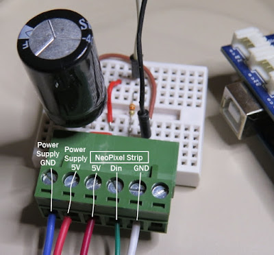
NeoPixel Strip connection

The NeoPixel strip is rolled up when you first get it. You will notice that there are wires on both sides of the strip. This allows you to chain LED strips together to make longer strips. The more LEDs you have, the more current you will need. Connect your Arduino and power supply to the left side of the strip, with the arrows pointing to the right. (i.e. the side with the "female" jst connector).


NeoPixel Strip Wires

There are 5 wires that come pre-attached to either side of the LED strip.


You don't have to use ALL FIVE wires, however you will need at least one of each colour: red, white & green.


Fritzing sketch

The following diagram will show you how to wire everything together
 
(click to enlarge)

Arduino Power considerations

Please note that the Arduino is powered by a USB cable.
If you plan to power the Arduino from your power supply, you will need to disconnect the USB cable from the Arduino FIRST, then connect a wire from the 5V line on the Power supply to the VIN pin on the Arduino. Do NOT connect the USB cable to the Arduino while the VIN wire is connected.


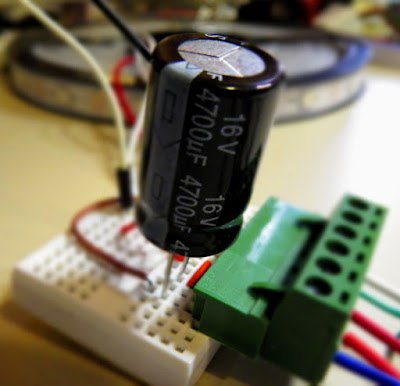
Large Capacitor

Adafruit also recommend the use of a large capacitor across the + and - terminals of the LED strip to "prevent the initial onrush of current from damaging the pixels". Adafruit recommends a capacitor that is 1000uF, 6.3V or higher. I used a 4700uF 16V Electrolytic Capacitor.


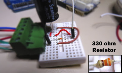
Resistor on Data Pin

Another recommendation from Adafruit is to place a "300 to 500 Ohm resistor" between the Arduino's data pin and the data input on the first NeoPixel to prevent voltage spikes that can damage the first pixel. I used a 330 Ohm resistor.


Grove Ear-clip heart rate sensor connection

The Grove Base shield makes it easy to connect Grove modules to the Arduino. If you have a Grove Base shield, you will need to connect the Ear-clip heart rate sensor to Digital pin 2 as per the diagram below.


Completed construction

Once you have everything connected, you can plug the USB cable into the Arduino, and turn on the LED power supply. Attach the ear-clip to your ear (or to your finger) and allow a few seconds to allow the sensor to register your pulse. The LED strip will light up with every heart beat with an animation that moves from one end of the strip to the other in just three heart beats. When the ear-clip is not connected to your ear or finger, the LEDs should remain off. However, the ear clip may "trigger" a heart beat when opening or closing the clip.
 
Here is a picture of all the components (fully assembled).


Concluding comments


This very affordable LED strip allows you to create amazing animations over a greater distance. I thought that having less LEDs per metre would make the animations look "jittery", but I was wrong, they look amazing. One of the good things about this strip is the amount of space between each Neopixel, allowing you to easily cut and join the strip to the size and shape you need.
 
This LED strip is compatible with the FastLED library, which makes for easy LED animation programming. While I used this LED strip to display my heart beat, you could just as easily use it to display the output of any other sensor attached to the Arduino.


If you like this page, please do me a favour and show your appreciation :

 
Visit my ArduinoBasics Google + page.
Follow me on Twitter by looking for ScottC @ArduinoBasics.
I can also be found on Pinterest and Instagram.
Have a look at my videos on my YouTube channel.


This project would not have been possible without OpenLab's collaborative effort.
Please visit their site for more cool projects.


However, if you do not have a google profile...
Feel free to share this page with your friends in any way you see fit.

NeoPixel Heart Beat Display


Project Description


In this project, your heart will control a mesmerising LED sequence on a 5 metre Neopixel LED strip with a ws2812B chipset. Every heart beat will trigger a LED animation that will keep you captivated and attached to your Arduino for ages. The good thing about this project is that it is relatively easy to set up, and requires no soldering. The hardest part is downloading and installing the FastLED library into the Arduino IDE, but that in itself is not too difficult. The inspiration and idea behind this project came from Ali Murtaza, who wanted to know how to get an LED strip to pulse to his heart beat.
 
Have a look at the video below to see this project in action.


The Video


Parts Required:


Power Requirements

Before you start any LED strip project, the first thing you will need to think about is POWER. According to the Adafruit website, each individual NeoPixel LED can draw up to 60 milliamps at maximum brightness - white. Therefore the amount of current required for the entire strip will be way more than your Arduino can handle. If you try to power this LED strip directly from your Arduino, you run the risk of damaging not only your Arduino, but your USB port as well. The Arduino will be used to control the LED strip, but the LED strip will need to be powered by a separate power supply. The power supply you choose to use is important. It must provide the correct voltage, and must able to supply sufficient current.
 

Operating Voltage (5V)

The operating voltage of the NeoPixel strip is 5 volts DC. Excessive voltage will damage/destroy your NeoPixels.

Current requirements (9.0 Amps)

OpenLab recommend the use of a 5V 10A power supply. Having more Amps is OK, providing the output voltage is 5V DC. The LEDs will only draw as much current as they need. To calculate the amount of current this 5m strip can draw with all LEDs turned on at full brightness - white:

30 NeoPixel LEDs x 60mA x 5m = 9000mA = 9.0 Amps for a 5 metre strip.

Therefore a 5V 10A power supply would be able to handle the maximum current (9.0 Amps) demanded by a 5m NeoPixel strip containing a total of 150 LEDs.


Arduino Libraries and IDE


Before you start to hook up any components, upload the following sketch to the Arduino microcontroller. I am assuming that you already have the Arduino IDE installed on your computer. If not, the IDE can be downloaded from here.
 
The FastLED library is useful for simplifying the code for programming the NeoPixels. The latest "FastLED library" can be downloaded from here. I used FastLED library version 3.0.3 in this project.
 
If you have a different LED strip or your NeoPixels have a different chipset, make sure to change the relevant lines of code to accomodate your hardware. I would suggest you try out a few of the FastLED library examples before using the code below, so that you become more familiar with the library, and will be better equipped to make the necessary changes. If you have a 5 metre length of the NeoPixel 30 LED/m strip with the ws2812B chipset, then you will not have to make any modification below.
 

ARDUINO CODE:


1
2
3
4
5
6
7
8
9
10
11
12
13
14
15
16
17
18
19
20
21
22
23
24
25
26
27
28
29
30
31
32
33
34
35
36
37
38
39
40
41
42
43
44
45
46
47
48
49
50
51
52
53
54
55
56
57
58
59
60
61
62
63
64
65
66
67
68
69
70
71
72
73
74
75
76
77
78
79
80
81
82
83
84
85
86
87
88
89
90
91
92
93
94
95
96
97
98
99
100
101
102
103
104
105
106
107
108
109
110
111
112
113
114
115
116
117
118
119
120
121
122
123
124
125
126
127
128
129
130
131
132
133
134
135
136
137
138
139
140
/* ================================================================================================ Project: NeoPixel Heart Beat Display Neopixel chipset: ws2812B (30 LED/m strip) Author: Scott C Created: 8th July 2015 Arduino IDE: 1.6.4 Website: http://arduinobasics.blogspot.com/p/arduino-basics-projects-page.html Description: This sketch will display a heart beat on a 5m Neopixel LED strip. Requires a Grove Ear-clip heart rate sensor and a Neopixel strip. This project makes use of the FastLED library: http://fastled.io/ You may need to modify the code below to accomodate your specific LED strip. See the FastLED library site for more details. ================================================================================================== */ //This project needs the FastLED library - link in the description. #include "FastLED.h" //The total number of LEDs being used is 150 #define NUM_LEDS 150 // The data pin for the NeoPixel strip is connected to digital Pin 6 on the Arduino #define DATA_PIN 6 //Attach the Grove Ear-clip heart rate sensor to digital pin 2 on the Arduino. #define EAR_CLIP 2 //Initialise the LED array CRGB leds[NUM_LEDS]; //Initialise the global variables used to control the LED animation int ledNum = 0; //Keep track of the LEDs boolean beated = false; //Used to identify when the heart has beated int randomR = 0; //randomR used to randomise the fade-out of the LEDs //================================================================================================ // setup() : Is used to initialise the LED strip //================================================================================================ void setup() { FastLED.addLeds<NEOPIXEL,DATA_PIN>(leds, NUM_LEDS); //Set digital pin 2 (Ear-clip heart rate sensor) as an INPUT pinMode(EAR_CLIP, INPUT);} //================================================================================================ // loop() : Take readings from the Ear-clip sensor, and display the animation on the LED strip //================================================================================================ void loop() { //If the Ear-clip sensor moves from LOW to HIGH, call the beatTriggered method if(digitalRead(EAR_CLIP)>0){ //beatTriggered() is only called if the 'beated' variable is false. //This prevents multiple triggers from the same beat. ifbeated){ beatTriggered(); } } else { beated = false; //Change the 'beated' variable to false when the Ear-clip heart rate sensor is reading LOW. } //Fade the LEDs by 1 unit/cycle, when the heart is at 'rest' (i.e. between beats) fadeLEDs(5);} //================================================================================================ // beatTriggered() : This is the LED animation sequence when the heart beats //================================================================================================ void beatTriggered(){ //Ignite 30 LEDs with a red value between 0 to 255 for(int i = 0; i<30; i++){ //The red channel is randomised to a value between 0 to 255 leds[ledNum].r=random8(); FastLED.show(); //Call the fadeLEDs method after every 3rd LED is lit. if(ledNum%3==0){ fadeLEDs(5); } //Move to the next LED ledNum++; //Make sure to move back to the beginning if the animation falls off the end of the strip if(ledNum>(NUM_LEDS-1)){ ledNum=0; } } //Ignite 20 LEDS with a blue value between 0 to 120 for(int i = 0; i<20; i++){ //The blue channel is randomised to a value between 0 to 120 leds[ledNum].b=random8(120); FastLED.show(); //Call the fadeLEDs method after every 3rd LED is lit. if(ledNum%3==0){ fadeLEDs(5); } //Move to the next LED ledNum++; //Make sure to move back to the beginning if the animation falls off the end of the strip if(ledNum>(NUM_LEDS-1)){ ledNum=0; } } //Change the 'beated' variable to true, until the Ear-Clip sensor reads LOW. beated=true;} //================================================================================================ // fadeLEDs() : The fading effect of the LEDs when the Heart is resting (Ear-clip reads LOW) //================================================================================================ void fadeLEDs(int fadeVal){ for (int i = 0; i<NUM_LEDS; i++){ //Fade every LED by the fadeVal amount leds[i].fadeToBlackBy( fadeVal ); //Randomly re-fuel some of the LEDs that are currently lit (1% chance per cycle) //This enhances the twinkling effect. if(leds[i].r>10){ randomR = random8(100); if(randomR<1){ //Set the red channel to a value of 80 leds[i].r=80; //Increase the green channel to 20 - to add to the effect leds[i].g=20; } } } FastLED.show();}


NeoPixel Strip connection

The NeoPixel strip is rolled up when you first get it. You will notice that there are wires on both sides of the strip. This allows you to chain LED strips together to make longer strips. The more LEDs you have, the more current you will need. Connect your Arduino and power supply to the left side of the strip, with the arrows pointing to the right. (i.e. the side with the "female" jst connector).


NeoPixel Strip Wires

There are 5 wires that come pre-attached to either side of the LED strip.


You don't have to use ALL FIVE wires, however you will need at least one of each colour: red, white & green.


Fritzing sketch

The following diagram will show you how to wire everything together
 
(click to enlarge)

Arduino Power considerations

Please note that the Arduino is powered by a USB cable.
If you plan to power the Arduino from your power supply, you will need to disconnect the USB cable from the Arduino FIRST, then connect a wire from the 5V line on the Power supply to the 5V pin on the Arduino. Do NOT connect the USB cable to the Arduino while the 5V wire is connected to the Arduino.


Large Capacitor

Adafruit also recommend the use of a large capacitor across the + and - terminals of the LED strip to "prevent the initial onrush of current from damaging the pixels". Adafruit recommends a capacitor that is 1000uF, 6.3V or higher. I used a 4700uF 16V Electrolytic Capacitor.


Resistor on Data Pin

Another recommendation from Adafruit is to place a "300 to 500 Ohm resistor" between the Arduino's data pin and the data input on the first NeoPixel to prevent voltage spikes that can damage the first pixel. I used a 330 Ohm resistor.


Grove Ear-clip heart rate sensor connection

The Grove Base shield makes it easy to connect Grove modules to the Arduino. If you have a Grove Base shield, you will need to connect the Ear-clip heart rate sensor to Digital pin 2 as per the diagram below.


Completed construction

Once you have everything connected, you can plug the USB cable into the Arduino, and turn on the LED power supply. Attach the ear-clip to your ear (or to your finger) and allow a few seconds to allow the sensor to register your pulse. The LED strip will light up with every heart beat with an animation that moves from one end of the strip to the other in just three heart beats. When the ear-clip is not connected to your ear or finger, the LEDs should remain off. However, the ear clip may "trigger" a heart beat when opening or closing the clip.
 
Here is a picture of all the components (fully assembled).


Concluding comments


This very affordable LED strip allows you to create amazing animations over a greater distance. I thought that having less LEDs per metre would make the animations look "jittery", but I was wrong, they look amazing. One of the good things about this strip is the amount of space between each Neopixel, allowing you to easily cut and join the strip to the size and shape you need.
 
This LED strip is compatible with the FastLED library, which makes for easy LED animation programming. While I used this LED strip to display my heart beat, you could just as easily use it to display the output of any other sensor attached to the Arduino.


If you like this page, please do me a favour and show your appreciation :

 
Visit my ArduinoBasics Google + page.
Follow me on Twitter by looking for ScottC @ArduinoBasics.
I can also be found on Pinterest and Instagram.
Have a look at my videos on my YouTube channel.


This project would not have been possible without OpenLab's collaborative effort.
Please visit their site for more cool projects.


However, if you do not have a google profile...
Feel free to share this page with your friends in any way you see fit.

Send HEX values to Arduino

FIVE MINUTE TUTORIAL

Project Description: Sending Hex values to an Arduino UNO


This simple tutorial will show you how to send Hexadecimal values from a computer to an Arduino Uno. The "Processing" programming language will be used to send the HEX values from the computer when a mouse button is pressed. The Arduino will use these values to adjust the brightness of an LED.


Learning Objectives


  • To Send Hexadecimal (Hex) values from a computer to the Arduino
  • Trigger an action based on the press of a mouse button
  • Learn to create a simple Computer to Arduino interface
  • Use Arduino's PWM capabilities to adjust brightness of an LED
  • Learn to use Arduino's analogWrite() function
  • Create a simple LED circuit


Parts Required:


Fritzing Sketch


The diagram below will show you how to connect an LED to Digital Pin 10 on the Arduino.
Don't forget the 330 ohm resistor !


Arduino Sketch


The latest version of Arduino IDE can be downloaded here.
 
  1
2
3
4
5
6
7
8
9
10
11
12
13
14
15
16
17
18
19
20
21
22
23
24
25
26
27
28
29
30
31
/* ==================================================================================================================================================
         Project: 5 min tutorial: Send Hex from computer to Arduino
          Author: Scott C
         Created: 21th June 2015
     Arduino IDE: 1.6.4
         Website: http://arduinobasics.blogspot.com/p/arduino-basics-projects-page.html
     Description: Arduino Sketch used to adjust the brightness of an LED based on the values received
                  on the serial port. The LED needs to be connected to a PWM pin. In this sketch
                  Pin 10 is used, however you could use Pin 3, 5, 6, 9, or 11 - if you are using an Arduino Uno.
===================================================================================================================================================== */

byte byteRead; //Variable used to store the byte received on the Serial Port
int ledPin = 10; //LED is connected to Arduino Pin 10. This pin must be PWM capable.

void setup() {
 Serial.begin(9600); //Initialise Serial communication with the computer
 pinMode(ledPin, OUTPUT); //Set Pin 10 as an Output pin
 byteRead = 0;                   //Initialise the byteRead variable to zero.
}

void loop() {
  if(Serial.available()) {
    byteRead = Serial.read(); //Update the byteRead variable with the Hex value received on the Serial COM port.
  }
  
  analogWrite(ledPin, byteRead); //Use PWM to adjust the brightness of the LED. Brightness is determined by the "byteRead" variable.
}


Processing Sketch


The latest version of the Processing IDE can be downloaded here.
 
  1
2
3
4
5
6
7
8
9
10
11
12
13
14
15
16
17
18
19
20
21
22
23
24
25
26
27
28
29
30
31
32
33
34
35
36
37
38
39
40
41
42
43
/* ==================================================================================================================================================
         Project: 5 min tutorial: Send Hex from computer to Arduino
          Author: Scott C
         Created: 21th June 2015
  Processing IDE: 2.2.1
         Website: http://arduinobasics.blogspot.com/p/arduino-basics-projects-page.html
     Description: Processing Sketch used to send HEX values from computer to Arduino when the mouse is pressed.
                  The alternating values 0xFF and 0x00 are sent to the Arduino Uno to turn an LED on and off.
                  You can send any HEX value from 0x00 to 0xFF. This sketch also shows how to convert Hex strings
                  to Hex numbers.
===================================================================================================================================================== */

import processing.serial.*; //This import statement is required for Serial communication

Serial comPort;                       //comPort is used to write Hex values to the Arduino
boolean toggle = false; //toggle variable is used to control which hex variable to send
String zeroHex = "00"; //This "00" string will be converted to 0x00 and sent to Arduino to turn LED off.
String FFHex = "FF"; //This "FF" string will be converted to 0xFF and sent to Arduino to turn LED on.

void setup(){
    comPort = new Serial(this, Serial.list()[0], 9600); //initialise the COM port for serial communication at a baud rate of 9600.
    delay(2000);                      //this delay allows the com port to initialise properly before initiating any communication.
    background(0); //Start with a black background.
    
}


void draw(){ //the draw() function is necessary for the sketch to compile
    //do nothing here //even though it does nothing.
}


void mousePressed(){ //This function is called when the mouse is pressed within the Processing window.
  toggle = ! toggle;                   //The toggle variable will change back and forth between "true" and "false"
  if(toggle){ //If the toggle variable is TRUE, then send 0xFF to the Arduino
     comPort.write(unhex(FFHex)); //The unhex() function converts the "FF" string to 0xFF
     background(0,0,255); //Change the background colour to blue as a visual indication of a button press.
  } else {
    comPort.write(unhex(zeroHex)); //If the toggle variable is FALSE, then send 0x00 to the Arduino
    background(0); //Change the background colour to black as a visual indication of a button press.
  }
}


The Video


The tutorial above is a quick demonstration of how to convert Hex strings on your computer and send them to an Arduino. The Arduino can use the values to change the brightness of an LED as shown in this tutorial, however you could use it to modify the speed of a motor, or to pass on commands to another module. Hopefully this short tutorial will help you with your project. Please let me know how it helped you in the comments below.


If you like this page, please do me a favour and show your appreciation :

 
Visit my ArduinoBasics Google + page.
Follow me on Twitter by looking for ScottC @ArduinoBasics.
I can also be found on Pinterest and Instagram.
Have a look at my videos on my YouTube channel.


However, if you do not have a google profile...
Feel free to share this page with your friends in any way you see fit.