Posts with «led» label

MacGyvered Optoisolator is a Great Introduction
Sometimes the best way to learn about a technology is to just build something yourself. That’s what [Dan] did with his DIY optoisolator. The purpose of an optoisolator is to allow two electrical systems to communicate with each other without being electrically connected. Many times this is done to prevent noise from one circuit from bleeding over into another.

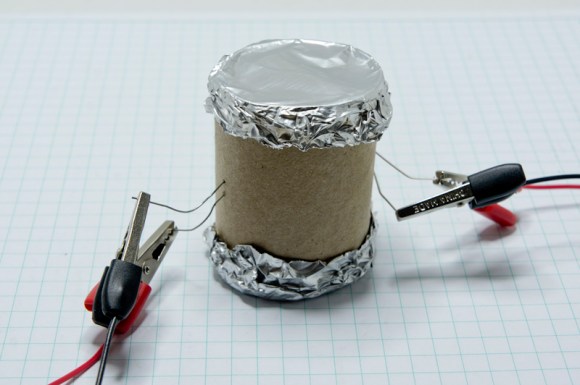
[Dan] built his incredibly simple optoisolator using just a toilet paper tube, some aluminum foil, an LED, and a photo cell. The electrical components are mounted inside of the tube and the ends of the tube are sealed with foil. That’s all there is to it. To test the circuit, he configured an Arduino to send PWM signals to the LED inside the tube at various pulse widths. He then measured the resistance on the other side and graphed the resulting data. The result is a curve that shows the LED affects the sensor pretty drastically at first, but then gets less and less effective as the frequency of the signal increases.

[Dan] then had some more fun with his project by testing it on a simple temperature controller circuit. An Arduino reads a temperature sensor and if the temperature rises above a certain value, it turns on a fan to cool the sensor off again. [Dan] first graphed the sensor data with no fan hooked up. He only used ambient air to cool things down. The resulting graph is a pretty smooth curve. Next he hooked the fan up and tried again. This time the graph went all kinds of crazy. Every time the fan turned on, it created a bunch of electrical noise that prevented the Arduino from getting an accurate analog reading of the temperature sensor.

The third test was to remove the motor circuit and move it to its own bread board. The only thing connecting the Arduino circuit to the fan was a wire for the PWM signal and also a common ground. This smoothed out the graph but it was still a bit… lumpy. The final test was to isolate the fan circuit from the temperature sensor and see if it helped the situation. [Dan] hooked up his optoisolator and tried again. This time the graph was nice and smooth, just like the original graph.

While this technology is certainly not new or exciting, it’s always great to see someone learning by doing. What’s more is [Dan] has made all of his schematics and code readily available so others can try the same experiment and learn it for themselves.


Filed under: Arduino Hacks

The Arduweenie

This is the tell-all guide to #Arduweenie, a bewitching maker project brought to you by Tenaya Hurst of Rogue Making and dog hunter LLC.  My project is a wire frame in the shape of a dachshund dog wrapped with a 5 meter long RGB LED strip which I program.  That’s […]

Read more on MAKE

MAKE » Arduino 16 Sep 13:01

LEDs Turn This Paper Map into a Tram Tracker

Public transit can be a wonderful thing. It can also be annoying if the trains are running behind schedule. These days, many public transit systems are connected to the Internet. This means you can check if your train will be on time at any moment using a computer or smart phone. [Christoph] wanted to take this concept one step further for the Devlol hackerspace is Linz, Austria, so he built himself an electronic tracking system (Google translate).

[Christoph] started with a printed paper map of the train system. This was placed inside what began as an ordinary picture frame. Then, [Christoph] strung together a series of BulletPixel2 LEDs in parallel. The BulletPixel2 LEDs are 8mm tri-color LEDs that also contain a small controller chip. This allows them to be controlled serially using just one wire. It’s similar to having an RGB LED strip, minus the actual strip. [Christoph] used 50 LEDs when all was said and done. The LEDs were mounted into the photo frame along the three main train lines; red, green, and blue. The color of the LED obviously corresponds to the color of the train line.

The train location data is pulled from the Internet using a Raspberry Pi. The information must be pulled constantly in order to keep the map accurate and up to date. The Raspberry Pi then communicates with an Arduino Uno, which is used to actually control the string of LEDs. The electronics can all be hidden behind the photo frame, out of site. The final product is a slick “radar” for the local train system.


Filed under: Arduino Hacks, Raspberry Pi

Arduino Powered Digital Kaleidoscope

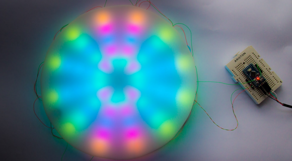
[Jose's] latest project brings an old visual effect toy up to date with digital electronics. Most of us are familiar with inexpensive kaleidoscope toys. Some of us have even built cheap versions of them with paper tubes, mirrors, and beads. [Jose] wanted to try to recreate the colorful pattern effects created by a kaleidoscope using an Arduino and an addressable LED strip.

The build is actually pretty simple. The base is a disc of PVC cut to just a few inches in diameter. [Jose] started with an addressable LED strip containing 60 LEDs. He then cut it into 12 sections, each containing five LEDs. The smaller strips were then mounted to the disc, similar to spokes on a bicycle wheel. The LED strip already has an adhesive backing, so that part was trivial.

The final step was to add some kind of diffuser screen. The LED strips on their own are not all that interesting. The diffuser allows the light to blend together, forming interesting patterns that are more reminiscent of the patterns you might see in a real kaleidoscope. Without the diffuser you would just see individual points of light, rather than blended color patterns.

The whole thing is controlled by a small Arduino. [Jose] has made the code available at the bottom of his blog post. Be sure to watch the video of the system in action below.


Filed under: Arduino Hacks
Hack a Day 06 Sep 12:00

What Everyone Needs: An Eight-Foot LED Light Staff

Hackaday.io blogger 'Risknc' updates his Light Staff prototype, much to the excitement of the LARPing community. It is a 8-foot staff filled with High Intensity LEDs that put on quite a show.

Read more on MAKE

A Custom Bicycle Dashboard

If you’re not satisfied with the lightweight digital speedometer that you can buy at your local bike shop, why not build your own bicycle dashboard using various electrical components and wood? DJ decided to do just that, and gives instructions with an electrical schematic, parts list, and Arduino sketch, in […]

Read more on MAKE

MAKE » Arduino 21 Aug 19:01

Voice Controlled RGB LED Lamp

[Saurabh] wanted a quick project to demonstrate how easy it can be to build devices that are voice controlled. His latest Instructable does just that using an Arduino and Visual Basic .Net.

[Saurabh] decided to build a voice controlled lamp. He knew he wanted it to change colors as well as be energy-efficient. It also had to be easy to control. The obvious choice was to use an RGB LED. The LED on its own wouldn’t be very interesting. He needed something to diffuse the light, like a lampshade. [Saurabh] decided to start with an empty glass jar. He filled the jar with gel wax, which provides a nice surface to diffuse the light.

The RGB LED was mounted underneath the jar’s screw-on cover. [Saurabh] soldered a 220 ohm current limiting resistor to each of the three anodes of the LED. A hole was drilled in the cap so he’d have a place to run the wires. The LED was then hooked up to an Arduino Leonardo.

The Arduino sketch has several built-in functions to set all of the colors, and also fade. [Saurabh] then wrote a control interface using Visual Basic .Net. The interface allows you to directly manipulate the lamp, but it also has built-in voice recognition functionality. This allows [Saurabh] to use his voice to change the color of the lamp, turn it off, or initiate a fading routing. You can watch a video demonstration of the voice controls below.


Filed under: Arduino Hacks, led hacks

3D Printed Bracelet Illuminates On The Beat

Maker Michael Barretta created an LED bracelet that is responsive to sound by combining the technology of light organs and Adafruit’s GEMMA microcontroller. The result is groovy.

Read more on MAKE

MAKE » Arduino 15 Aug 23:01

Teaching the Word Clock Some New Tricks

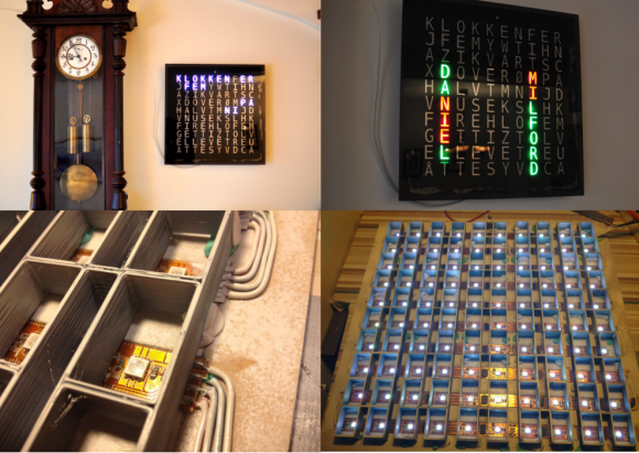
[Joakim] has built a clock that spells out the time in words. Wait a second – word clock, what is this, 2009? Word clocks are one of those projects that have become timeless. When we see a build that stands out, we make sure to write it up. [Joakim's] clock is special for a number of reasons. The time is spelled out in Norwegian, and since the clock is a birthday gift for [Daniel], [Joakim] added the his full name to the clock’s repertoire.

One of the hard parts of word clock design is controlling light spill. [Joakim] used a simple 3D printed frame to box each LED in. This keeps the spill under control and makes everything easier to read. The RGB LED’s [Joakim] used are also a bit different from the norm. Rather than the WS2812 Neopixel, [Joakim] used LPD8806 LED strips. On the controller side [Joakim] may have gone a bit overboard in his choice of an Arduino Yun, but he does put the ATmega328 and Embedded Linux machine to good use.

The real magic happens at boot. [Daniel's] name lights up in red, with various letters going green as each step completes. A green ‘D’ indicates an IP address was obtained from the router’s DHCP server. ‘N’ switches to green when four NTP servers have been contacted, and the Linux processor is reasonably sure it has the correct time. The last letter to change will be the ‘E’, which reports ambient light.

[Joakim] added a web interface to trigger his new features, such as a rainbow color palette, or the ability to show minutes by changing the color of the letters K,L,O,K. The final result is a slick package, which definitely brings a 2009 era design up to 2014 standards!


Filed under: Arduino Hacks, clock hacks

POV Display Does it on the Cheap

[Sholto] hacked together this ultra low-budget spinning display. He calls it a zoetrope, but we think it’s actually an LED based Persistence Of Vision (POV) affair. We’ve seen plenty of POV devices in the past, but this one proves that a hack doesn’t have to be expensive or pretty to work!

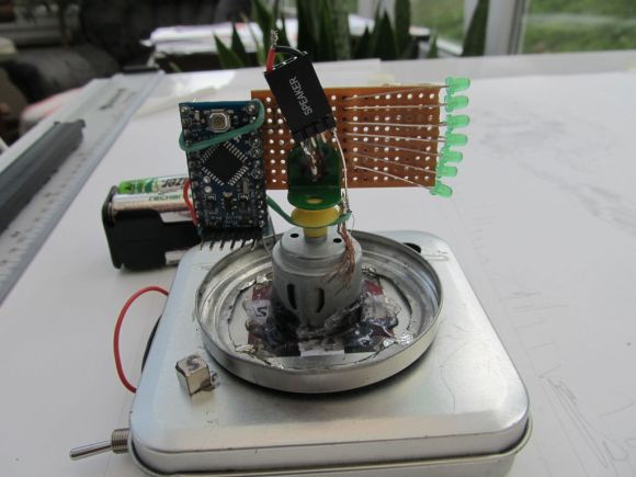
The major parts of the POV display were things that [Sholto] had lying around. A couple of candy tins, a simple brushed hobby motor, an Arduino Pro Mini, 7 green LEDs, and an old hall effect sensor were all that were required. Fancy displays might use commercial slip rings to transfer power, but [Sholto] made it work on the cheap!

The two tins provide a base for the display and the negative supply for the Arduino. The tins are soldered together and insulated from the motor, which is hot glued into the lower tin. A paper clip contacts the inside of the lid, making the entire assembly a slip ring for the negative side of the Arduino’s power supply. Some copper braid rubbing on the motor’s metal case forms the positive side.

[Sholto] chose his resistors to slightly overdrive his green LEDs. This makes the display appear brighter in POV use. During normal operation, the LEDs won’t be driven long enough to cause damage. If the software locks up with LEDs on though, all bets are off!

[Sholto] includes software for a pretty darn cool looking “saw wave” demo, and a simple numeric display. With a bit more work this could make a pretty cool POV clock, at least for as long as the motor brushes hold up!

[via Instructables]


Filed under: led hacks