Posts with «led» label

Hacking the Macetech RGB Shades

Some of the more in-your-face pieces of wearable technology are macetech’s RGB Shades and LED Matrix Shades. They’re shutter shade sunglasses with a twist: the front surface is crammed with individually controllable LEDs. It’s an attention-grabbing effect, and the person wearing the Shades can see through the LED array just […]

Read more on MAKE

MAKE » Arduino 18 Jul 22:02
arduino  general  led  macetech  music  rgb  shades  

Future’s so Bright, I Gotta Wear LED Shades

You can buy the new LED Matrix Shades from macetech on their online store. Or build the original version, now available as an open source design.

Read more on MAKE

Arduino-Controlled LED Chandelier Made With Mini Jars

Could your humble abode use a little microcontrolled LED pizzaz? Why not class up the joint with a stunning arduino-controlled chandelier made from jars using this brilliant tutorial?

Read more on MAKE

MAKE » Arduino 10 Jul 15:01

Glo-Mo: Designing a High Tech Dance

“To me, the lights were artwork of themselves. There were the dancers dancing under art, with art on their bodies, so it just brought the whole picture together,” said Danielle Sampson, a dance teacher at Grand Center Arts Academy. I attend Grand Center Arts Academy, a school for the fine […]

Read more on MAKE

Custom Electronics and LED Panels Brighten Up a Nightclub

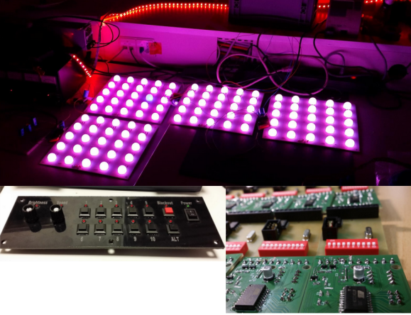
When [Robert] is presented with a challenge, he doesn’t back down. His friend dreamed of reusing some old LED panels by mounting them to the ceiling of the friend’s night club. Each panel consists of a grid of five by five red, green, and blue LEDs for a total of 75 LEDs per panel. It sounded like a relatively simple task but there were a few caveats. First, the controller box that came with the panels could only handle 16 panels and the friend wanted to control 24 of them. Second, the only input device for the controller was an infrared remote. The friend wanted an easy way for DJ’s to control the color of the panels and the infrared remote was not going to cut it. Oh yea, he also gave [Robert] just three weeks to make this happen.

[Robert] started out by building a circuit that could be duplicated to control each panel. The brain of this circuit is an ATtiny2313. For communication between panels, [Robert] chose to go with the DMX protocol. This was a good choice considering DMX is commonly used to control stage lighting effects. The SN75176 IC was chosen to handle this communication. In his haste to get this PCB manufactured [Robert] failed to realize that the LED panels were designed common cathode, as opposed to his 25 shiny new PCB’s which were designed to work with a common anode design. To remedy this, he switched out all of the n-channel MOSFET with p-channel MOSFET. He also spent a couple of hours manually cutting through traces and rewiring the board. After all of this, he discovered yet another problem. The LED’s were being powered from the same 5V source as the microcontroller. This lead to power supply issues resulting in the ATtiny constantly resetting. The solution was to add some capacitors.

Click past the break for more on [Robert's] LED panels.

As for software, [Robert] completely filled the ATtiny’s memory. He used three channels to control red, green, and blue. He added a fourth channel to control pre-designed animation effects such as fading, strobe, and random color. The DIP switches are normally used to set the address of the panel, but there is a second option to put the panel into standalone mode. In this mode, the switches are used to program the panel to perform specific effects with no DMX controller required.

Now that the panels were all designed and functioning, [Robert] still needed a way to control them. He used the laser cutter at Shackspace hackerspace to design the actual panel face and then mounted a bunch of buttons, switches, and potentiometers to it. All of those things were connected to a Teensy3 using perfboard and a hand wired circuit. Another SN75176 IC was used for the DMX communication from the control panel. The control panel allows the DJ to change between different pre-built animation effects, color effects, and also change the speed of the animations to match the speed of the music.


Filed under: led hacks
Hack a Day 31 May 12:00

The Centurion Project: LED Helmet

7 meters of RGB LEDs crammed onto a centurion’s helmet? It makes perfect sense once you see it in action. When you’re a creative developer with a name like Roman, you’re bound to find yourself recreating things from antiquity. Roman Cory found his inevitable foray into ancient Roman culture resulted […]

Read more on MAKE

MAKE » Arduino 01 May 16:01
arduino  costuming  general  led  music  

Teach kids how colors are made with the color machine

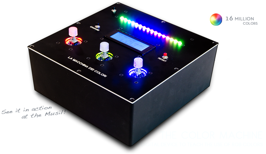
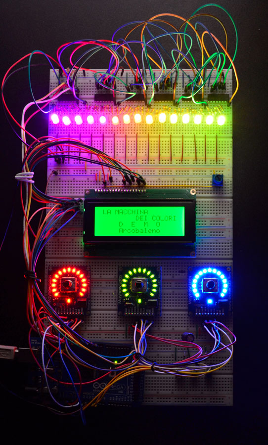
The Color Machine (La macchina dei colori, in Italian language) is a tool to teach children about the use and the operation of RGB color coding, which is used in all digital devices (TVs, smartphones, computers, etc.). It was created with Arduino Mega by an italian duo composed by Fabio Ghidini and Stefano Guerrini:

Using 3 knobs you can increase the percentages of red, green and blue separately, and the LED strip at the top of the machine lights up consistently with the color mix choosen.

The Color Machine has 4 different operating modes: “let’s create colors”, “guess the color”, “the names of the colors” and “demo”. Under the guidance of a teacher, children can play and learn at the same time to recreate colors with additive synthesis. This device is currently used in the educational workshops of Musil – Museum of Industry and Labour of Rodengo Saiano (Italy).


This is the first propotype:

Arduino Blog 09 Apr 11:05

Ninth day of freshman design seminar

The astute reader of this blog may notice that there was no “eighth day of freshman design seminar” post.  I was sick last Wednesday and unable to attend class, so I had the group tutor (a senior in bioengineering) take the class and have them discuss possible projects to take on.  I asked them to turn in proposals yesterday, but forgot to collect them—I’ll collect them tomorrow.  We’re about halfway through the course, so it is time for students to start on their projects.

I returned two homeworks yesterday: the colorimeter design and the RGB LED resistor sizing.

The colorimeter designs were not very good, lacking necessary details, but were somewhat better than previous spectrometer attempts. I think I’ll try reversing the order of those assignments in future, as the colorimeter is a simpler device. The biggest problem with the designs is that most of them were pieced together from web pages, with no citations.  Two of them were blatantly copied from Science Buddies, which has a decent design, but the students did not cite the source. I yelled “Cite your sources!” at the class, and explained that I could have flunked several of them out for plagiarism, and that in an upper-division course I would have. I hope they get the message, so that they don’t fail out later on. I decided not to prosecute academic integrity cases in this 2-unit, optional course, though I am making the science-buddy copyists redo the assignment.

I then explained to students the mistake I had made in the photodiode explanations (see Lying to my students) and corrected the understanding of the “open-circuit voltage” spec from the photodiode datasheets. I think that the students are a little more comfortable about finding things on datasheets now—I hope that lasts for them.

We then went over one of the RGB LED datasheets and did the resistor sizing for it.  About a third of the class had done a decent job on that assignment, and I cleared up the common mistakes:

  • If a battery is used in a schematic, both ends need to be connected.  Other options are to use +5v and Gnd port symbols, or a +5V DC voltage source symbol.
  • The LED diode must be forward biased (with a large current flow), and the triangular shape of the diode symbol shows which way conventional current flows.
  • The voltage needed for determining the resistance is the voltage across the resistor, not the voltage across the diode, so it is 5v–VF, not VF.

I think I managed to get these points across—I relied fairly heavily on asking the students to do each step, so I’m pretty sure that at least half the class can now size a resistor for an LED.

Finally we could get to some new material. I wanted to show them how to program an Arduino, so we built up the standard blinking-LED first example for an Arduino.  To make it a little more interesting, I started with a true statement—I did not know whether the LED on pin 13 was hooked up with the anode or the cathode connected to pin 13.  We looked at the two possible circuits and how they would behave differently when the pin was high and when it was low.  I then explained “void setup()”, “void loop()”, and “pinMode(13,OUTPUT);”.  I had the students come up with the body of loop, feeding them the important constructs (digitalWrite and delay) only once they had expressed the action they wanted.  We ended up with a loop that help pin 13 high for a second and low for ¼ second.  After I typed in the program we had written, I showed them how to select the appropriate board type and download it to the Arduino.  The light blinked, and the students were able to figure out from the pattern of on and off that the LED was connected between pin 13 and GND (with a series resistor), with the anode towards pin 13.

I ran out of time and material at about the same time (a first for this quarter), and assigned the students to read about Arduino programming from the Arduino reference website, with particular attention to “if”, “while”, “pinMode”, “digitalWrite”, “digitalRead”, “analogRead”, and the timer functions.  I expect to go over some analogRead stuff in class tomorrow, and assign a small programming assignment over the weekend, probably using “Serial”.


Filed under: freshman design seminar Tagged: Arduino, bioengineering, colorimeter, engineering education, LED, photodiode

PIR Sensor (Part 2)


In this tutorial we will connect our HC-SR501 PIR (movement) Sensor to an Arduino UNO. The PIR sensor will be powered by the Arduino and when movement is detected, the PIR sensor will send a signal to Digital Pin 2. The Arduino will respond to this signal by illuminating the LED attached to Pin 13.

PIR Sensor (Part 1) : Showed that this sensor can be used in isolation (without an Arduino). However, I will still demonstrate how you can attach this sensor to the Arduino so that we can move forward to more advanced objectives and concepts.


Video


Parts Required


Fritzing Sketch


Arduino Sketch


 1
2
3
4
5
6
7
8
9
10
11
12
13
14
/*Simple PIR sketch: Written by ScottC, 19th Dec 2013

http://arduinobasics.blogspot.com/

----------------------------------------------------*/

void setup(){
pinMode(13,OUTPUT);
pinMode(2,INPUT);
}

void loop(){
digitalWrite(13,digitalRead(2));
}


The sketch above reads the signal coming in from the PIR sensor on Pin 2, and if it reads HIGH, it light up the LED attached to Pin 13. If it reads LOW, it will turn the LED off. This is all controlled by line 13 in the Arduino Sketch above.

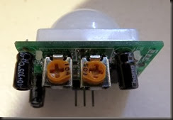
The following table helps to identify the purpose of the potentiometers on the PIR sensor. Most people say they use trial and error. I will attempt to reduce the mystery of these components on the PIR board.


104 (Left) – Max


LED on = 20 sec
LED off = 3 sec

When you move the 104 labelled potentiometer all the way to the left (max position), the LED will remain on for 20 seconds after movement is detected. The 20 seconds is independent of the other potentiometer (105) setting. When the LED turns off, it will remain off for 3 seconds before the sensor will trigger again from any further movement.


104 (Right) – Min


LED on = 1 sec
LED off = 3 sec

When you move the 104 labelled potentiometer all the way to the right (min position), the LED will remain on for 1 second after movement is detected. When the LED turns off, it will remain off for 3 seconds before the sensor will trigger again from any further movement.


105 (Left) – Max


Most sensitive – Detects movement from over 10 steps away.

The 105 labelled potentiometer controls the sensitivity of the PIR sensor. When in the left position, the PIR sensor is most sensitive and small amounts of movement will trigger the sensor. It detected my movement (ie a single step to the left of right) from over 10 steps away from the sensor. I was very impressed.


105 (Right) – Min


Least sensitive: Need significant movement for sensor to trigger. Detects movement from about 4 steps away.

When the 105 labelled potentiometer is twisted to the right, the PIR sensor becomes a lot less sensitive. I needed to take much bigger steps to the left or right to trigger the sensor (about 3 times the size compared to the left position). It also had a lot more trouble detecting movement occurring further away. It only really started to detect my movement when I was about 4 steps away from it. 

My preferred combination was 104-Right (min) + 105-Left (max), which meant that the sensor would remain on for only a short period of time, and detect any subtle movements in the room. This combination is displayed below:


I have not tested to see how it performs over a very long period with this setting, and whether it would suffer from false positive readings, but that could easily be fixed by turning the 105 labelled potentiometer a bit more to the right.