Posts with «led» label

Kit Review – Altronics 3 Digit Counter Module

Introduction

In this review we examine the three digit counter module kit from Altronics. The purpose of this kit is to allow you to … count things. You feed it a pulse, which it counts on the rising edge of the signal. You can have it count up or down, and each kit includes three digits.

You can add more digits, in groups of three with a maximum of thirty digits. Plus it’s based on simple digital electronics (no microcontrollers here) so there’s some learning afoot as well. Designed by Graham Cattley the kit was first described in the now-defunct (thanks Graham) January 1998 issue of Electronics Australia magazine.

Assembly

The kit arrives in the typical retail fashion:

And includes the magazine article reprint along with Altronics’ “electronics reference sheet” which covers many useful topics such as resistor colour codes, various formulae, PCB track widths, pinouts and more. There is also a small addendum which uses two extra (and included) diodes for input protection on the clock signal:

The counter is ideally designed to be mounted inside an enclosure of your own choosing, so everything required to build a working counter is included however that’s it:

No IC sockets, however I decided to live dangerously and not use them – the ICs are common and easily found. The PCBs have a good solder mask and silk screen:

With four PCBs (one each for a digit control and one for the displays) the best way to start was to get the common parts out of the way and fitted, such as the current-limiting resistors, links, ICs, capacitors and the display module. The supplied current-limiting resistors are for use with a 9V DC supply, however details for other values are provided in the instructions:

At this point you put one of the control boards aside, and then start fitting the other two to the display board. This involves holding the two at ninety degrees then soldering the PCB pads to the SIL pins on the back of the display board. Starting with the control board for the hundreds digit first:

… at this stage you can power the board for a quick test:

… then fit the other control board for the tens digit and repeat:

Now it’s time to work with the third control board. This one looks after the one’s column and also a few features of the board. Several functions such as display blanking, latch (freeze the display while still counting) and gate (start or stop counting) can be controlled and require resistors fitted to this board which are detailed in the instructions.

Finally, several lengths of wire (included) are soldered to this board so that they can run through the other two to carry signals such as 5V, GND, latch, reset, gate and so on:

These wires can then be pulled through and soldered to the matching pads once the last board has been soldered to the display board:

 You also need to run separate wires between the carry-out and clock-in pins between the digit control boards (the curved ones between the PCBs):

For real-life use you also need some robust connections for the power, clock, reset lines, etc., however for demonstration use I just used alligator clips. Once completed a quick power-up showed the LEDs all working:

How it works

Each digit is driven by a common IC pairing – the  4029 (data sheet) is a presettable up/down counter with a BCD (binary-coded decimal) output which feeds a 4511 (data sheet) that converts the BCD signal into outputs for a 7-segment LED display. You can count at any readable speed, and I threw a 2 kHz square-wave at the counter and it didn’t miss a beat. By default the units count upwards, however by setting one pin on the board LOW you can count downwards.

Operation

Using the counters is a simple matter of connecting power, the signal to count and deciding upon display blanking and the direction of counting. Here’s a quick video of counting up, and here it is counting back down.

Conclusion

This is a neat kit that can be used to count pulses from almost anything. Although some care needs to be taken when soldering, this isn’t anything that cannot be overcome without a little patience and diligence. So if you need to count something, get one ore more of these kits from Altronics. Full-sized images are available on flickr. And while you’re here – are you interested in Arduino? Check out my new book “Arduino Workshop” from No Starch Press – also shortly available from Altronics.

In the meanwhile have fun and keep checking into tronixstuff.com. Why not follow things on twitterGoogle+, subscribe  for email updates or RSS using the links on the right-hand column? And join our friendly Google Group – dedicated to the projects and related items on this website. Sign up – it’s free, helpful to each other –  and we can all learn something.

The post Kit Review – Altronics 3 Digit Counter Module appeared first on tronixstuff.

Tronixstuff 18 Nov 06:55

Project – LED Cube Spectrum Analyzer

Introduction

A few weeks ago I was asked about creating a musical-effect display with an RGB LED cube kit from Freetronics, and with a little work this was certainly possible using the MSGEQ7 spectrum analyser IC. In this project we’ll create a small add-on PCB containing the spectrum analyser circuit and show how it can drive the RGB LED cube kit.

Assumed knowledge

To save repeating myself, please familiarise yourself with the MSGEQ7 spectrum aanalyserIC in Chapter 48 of our Arduino tutorials. And learn more about the LED cube from our review and the product page.

You can get MSGEQ7 ICs from various sources, however they had varying results. We now recommend using the neat module from Tronixlabs.

The circuit

The LED cube already has an Arduino Leonardo-compatible built in to the main PCB, so all you need to do is build a small circuit that contains the spectrum analyzer which connects to the I/O pins on the cube PCB and also has audio input and output connections. First, consider the schematic:

For the purposes of this project our spectrum analyser will only display the results from one channel of audio – if you want stereo, you’ll need two! And note that the strobe, reset and DCOUT pins on the MSGEQ7 are labelled with the connections to the cube PCB. Furthermore the pinouts for the MSGEQ7 don’t match the physical reality – here are the pinouts from the MSGEQ7 data sheet (.pdf):

The circuit itself will be quite small and fit on a small amount of stripboard or veroboard. There is plenty of room underneath the cube to fit the circuit if so desired:

With a few moments you should be able to trace out your circuit to match the board type you have, remember to double-check before soldering. You will also need to connect the audio in point after the 1000 pF capacitor to a source of audio, and also pass it through so you can connect powered speakers, headphones, etc.

One method of doing so would be to cut up a male-female audio extension lead, and connect the shield to the GND of the circuit, and the signal line to the audio input on the circuit. Or if you have the parts handy and some shielded cable, just make your own input and output leads:

Be sure to test for shorts between the signal and shield before soldering to the circuit board. When finished, you should have something neat that you can hide under the cube or elsewhere:

Double-check your soldering for shorts and your board plan, then fit to the cube along with the audio source and speakers (etc).

Arduino Sketch

The sketch has two main functions – the first is to capture the levels from the MSGEQ7 and put the values for each frequency band into an array, and the second function is to turn on LEDs that represent the level for each band. If you’ve been paying attention you may be wondering how we can represent seven frequency bands with a 4x4x4 LED cube. Simple – by rotating the cube 45 degrees you can see seven vertical columns of LEDs:

So when looking from the angle as shown above, you have seven vertical columns, each with four levels of LEDs. Thus the strength of each frequency can be broken down into four levels, and then the appropriate LEDs turned on.

After this is done for each band, all the LEDs are turned off and the process repeats. For the sake of simplicity I’ve used the cube’s Arduino library to activate the LEDs, which also makes the sketch easier to fathom. The first example sketch only uses one colour:

// Freetronics CUBE4: and MSGEQ7 spectrum analyser
// MSGEQ7 strobe on A4, reset on D5, signal into A0

#include "SPI.h"
#include "Cube.h"
Cube cube;

int res = 5; // reset pins on D5
int left[7]; // store band values in these arrays
int band;

void setup()
{
  pinMode(res, OUTPUT); // reset
  pinMode(A4, OUTPUT); // strobe
  digitalWrite(res,LOW); 
  digitalWrite(A4,HIGH); 
  cube.begin(-1, 115200);
  Serial.begin(9600);
}

void readMSGEQ7()
// Function to read 7 band equalizers
{
  digitalWrite(res, HIGH);
  digitalWrite(res, LOW);
  for(band=0; band <7; band++)
  {
    digitalWrite(A4,LOW); // strobe pin on the shield - kicks the IC up to the next band 
    delayMicroseconds(30); // 
    left[band] = analogRead(0); // store band reading
    digitalWrite(A4,HIGH); 
  }
}

void loop()
{
  readMSGEQ7();

  for (band = 0; band < 7; band++)
  {
    // div each band strength into four layers, each band then one of the odd diagonals 

    // band one ~ 63 Hz
    if (left[0]>=768) { 
      cube.set(3,3,3, BLUE); 
    } 
    else       
      if (left[0]>=512) { 
      cube.set(3,3,2, BLUE); 
    } 
    else   
      if (left[0]>=256) { 
      cube.set(3,3,1, BLUE); 
    } 
    else       
      if (left[0]>=0) { 
      cube.set(3,3,0, BLUE); 
    } 

    // band two ~ 160 Hz
    if (left[1]>=768) 
    { 
      cube.set(3,2,3, BLUE); 
      cube.set(2,3,3, BLUE);      
    }  
    else
      if (left[1]>=512) 
      { 
        cube.set(3,2,2, BLUE); 
        cube.set(2,3,2, BLUE);      
      } 
      else   
        if (left[1]>=256) 
      { 
        cube.set(3,2,1, BLUE); 
        cube.set(2,3,1, BLUE);      
      } 
      else   
        if (left[1]>=0) 
      { 
        cube.set(3,2,0, BLUE); 
        cube.set(2,3,0, BLUE);      
      } 

    // band three ~ 400 Hz
    if (left[2]>=768) 
    { 
      cube.set(3,1,3, BLUE); 
      cube.set(2,2,3, BLUE);      
      cube.set(1,3,3, BLUE);            
    }  
    else
      if (left[2]>=512) 
      { 
        cube.set(3,1,2, BLUE); 
        cube.set(2,2,2, BLUE);      
        cube.set(1,3,2, BLUE);            
      } 
      else   
        if (left[2]>=256) 
      { 
        cube.set(3,1,1, BLUE); 
        cube.set(2,2,1, BLUE);      
        cube.set(1,3,1, BLUE);            
      } 
      else   
        if (left[2]>=0) 
      { 
        cube.set(3,1,0, BLUE); 
        cube.set(2,2,0, BLUE);      
        cube.set(1,3,0, BLUE);            
      } 

    // band four ~ 1 kHz
    if (left[3]>=768) 
    { 
      cube.set(3,0,3, BLUE); 
      cube.set(2,1,3, BLUE);      
      cube.set(1,2,3, BLUE);            
      cube.set(0,3,3, BLUE);                  
    }  
    else
      if (left[3]>=512) 
      { 
        cube.set(3,0,2, BLUE); 
        cube.set(2,1,2, BLUE);      
        cube.set(1,2,2, BLUE);            
        cube.set(0,3,2, BLUE);                        
      } 
      else   
        if (left[3]>=256) 
      { 
        cube.set(3,0,1, BLUE); 
        cube.set(2,1,1, BLUE);      
        cube.set(1,2,1, BLUE);      
        cube.set(0,3,1, BLUE);                        
      } 
      else   
        if (left[3]>=0) 
      { 
        cube.set(3,0,0, BLUE); 
        cube.set(2,1,0, BLUE);      
        cube.set(1,2,0, BLUE);            
        cube.set(0,3,0, BLUE);                        
      } 

    // band five  ~ 2.5 kHz
    if (left[4]>=768) 
    { 
      cube.set(2,0,3, BLUE); 
      cube.set(1,1,3, BLUE);      
      cube.set(0,2,3, BLUE);            
    }  
    else
      if (left[4]>=512) 
      { 
        cube.set(2,0,2, BLUE); 
        cube.set(1,1,2, BLUE);      
        cube.set(0,2,2, BLUE);            
      } 
      else   
        if (left[4]>=256) 
      { 
        cube.set(2,0,1, BLUE); 
        cube.set(1,1,1, BLUE);      
        cube.set(0,2,1, BLUE);      
      } 
      else   
        if (left[4]>=0) 
      { 
        cube.set(2,0,0, BLUE); 
        cube.set(1,1,0, BLUE);      
        cube.set(0,2,0, BLUE);            
      } 

    // band six   ~ 6.25 kHz
    if (left[5]>=768) 
    { 
      cube.set(1,0,3, BLUE); 
      cube.set(0,1,3, BLUE);      
    }  
    else
      if (left[5]>=512) 
      { 
        cube.set(1,0,2, BLUE); 
        cube.set(0,1,2, BLUE);      
      } 
      else   
        if (left[5]>=256) 
      { 
        cube.set(1,0,1, BLUE); 
        cube.set(0,1,1, BLUE);      
      } 
      else   
        if (left[5]>=0) 
      { 
        cube.set(1,0,0, BLUE); 
        cube.set(0,1,0, BLUE);      
      } 

    // band seven  ~ 16 kHz
    if (left[6]>=768) 
    { 
      cube.set(0,0,3, BLUE); 
    }  
    else
      if (left[6]>=512) 
      { 
        cube.set(0,0,2, BLUE); 
      } 
      else   
        if (left[6]>=256) 
      { 
        cube.set(0,0,1, BLUE); 
      } 
      else   
        if (left[6]>=0) 
      { 
        cube.set(0,0,0, BLUE); 
      } 
  }
  // now clear the CUBE, or if that's too slow - repeat the process but turn LEDs off
  cube.all(BLACK);
}

… and a quick video demonstration:

For a second example, we’ve used various colours:

// Freetronics CUBE4: and MSGEQ7 spectrum analyser
// MSGEQ7 strobe on A4, reset on D5, signal into A0
// now in colour!

#include "SPI.h"
#include "Cube.h"
Cube cube;

int res = 5; // reset pins on D5
int left[7]; // store band values in these arrays
int band;
int additional=0;

void setup()
{
  pinMode(res, OUTPUT); // reset
  pinMode(A4, OUTPUT); // strobe
  digitalWrite(res,LOW); 
  digitalWrite(A4,HIGH); 
  cube.begin(-1, 115200);
  Serial.begin(9600);
}

void readMSGEQ7()
// Function to read 7 band equalizers
{
  digitalWrite(res, HIGH);
  digitalWrite(res, LOW);
  for(band=0; band <7; band++)
  {
    digitalWrite(A4,LOW); // strobe pin on the shield - kicks the IC up to the next band 
    delayMicroseconds(30); // 
    left[band] = analogRead(0) + additional; // store band reading
    digitalWrite(A4,HIGH); 
  }
}

void loop()
{
  readMSGEQ7();

  for (band = 0; band < 7; band++)
  {
    // div each band strength into four layers, each band then one of the odd diagonals 

    // band one ~ 63 Hz
    if (left[0]>=768) { 
      cube.set(3,3,3, RED); 
    } 
    else       
      if (left[0]>=512) { 
      cube.set(3,3,2, YELLOW); 
    } 
    else   
      if (left[0]>=256) { 
      cube.set(3,3,1, YELLOW); 
    } 
    else       
      if (left[0]>=0) { 
      cube.set(3,3,0, BLUE); 
    } 

    // band two ~ 160 Hz
    if (left[1]>=768) 
    { 
      cube.set(3,2,3, RED); 
      cube.set(2,3,3, RED);      
    }  
    else
      if (left[1]>=512) 
      { 
        cube.set(3,2,2, YELLOW); 
        cube.set(2,3,2, YELLOW);      
      } 
      else   
        if (left[1]>=256) 
      { 
        cube.set(3,2,1, YELLOW); 
        cube.set(2,3,1, YELLOW);      
      } 
      else   
        if (left[1]>=0) 
      { 
        cube.set(3,2,0, BLUE); 
        cube.set(2,3,0, BLUE);      
      } 

    // band three ~ 400 Hz
    if (left[2]>=768) 
    { 
      cube.set(3,1,3, RED); 
      cube.set(2,2,3, RED);      
      cube.set(1,3,3, RED);            
    }  
    else
      if (left[2]>=512) 
      { 
        cube.set(3,1,2, YELLOW); 
        cube.set(2,2,2, YELLOW);      
        cube.set(1,3,2, YELLOW);            
      } 
      else   
        if (left[2]>=256) 
      { 
        cube.set(3,1,1, YELLOW); 
        cube.set(2,2,1, YELLOW);      
        cube.set(1,3,1, YELLOW);            
      } 
      else   
        if (left[2]>=0) 
      { 
        cube.set(3,1,0, BLUE); 
        cube.set(2,2,0, BLUE);      
        cube.set(1,3,0, BLUE);            
      } 

    // band four ~ 1 kHz
    if (left[3]>=768) 
    { 
      cube.set(3,0,3, RED); 
      cube.set(2,1,3, RED);      
      cube.set(1,2,3, RED);            
      cube.set(0,3,3, RED);                  
    }  
    else
      if (left[3]>=512) 
      { 
        cube.set(3,0,2, YELLOW); 
        cube.set(2,1,2, YELLOW);      
        cube.set(1,2,2, YELLOW);            
        cube.set(0,3,2, YELLOW);                        
      } 
      else   
        if (left[3]>=256) 
      { 
        cube.set(3,0,1, YELLOW); 
        cube.set(2,1,1, YELLOW);      
        cube.set(1,2,1, YELLOW);      
        cube.set(0,3,1, YELLOW);                        
      } 
      else   
        if (left[3]>=0) 
      { 
        cube.set(3,0,0, BLUE); 
        cube.set(2,1,0, BLUE);      
        cube.set(1,2,0, BLUE);            
        cube.set(0,3,0, BLUE);                        
      } 

    // band five  ~ 2.5 kHz
    if (left[4]>=768) 
    { 
      cube.set(2,0,3, RED); 
      cube.set(1,1,3, RED);      
      cube.set(0,2,3, RED);            
    }  
    else
      if (left[4]>=512) 
      { 
        cube.set(2,0,2, YELLOW); 
        cube.set(1,1,2, YELLOW);      
        cube.set(0,2,2, YELLOW);            
      } 
      else   
        if (left[4]>=256) 
      { 
        cube.set(2,0,1, YELLOW); 
        cube.set(1,1,1, YELLOW);      
        cube.set(0,2,1, YELLOW);      
      } 
      else   
        if (left[4]>=0) 
      { 
        cube.set(2,0,0, BLUE); 
        cube.set(1,1,0, BLUE);      
        cube.set(0,2,0, BLUE);            
      } 

    // band six   ~ 6.25 kHz
    if (left[5]>=768) 
    { 
      cube.set(1,0,3, RED); 
      cube.set(0,1,3, RED);      
    }  
    else
      if (left[5]>=512) 
      { 
        cube.set(1,0,2, YELLOW); 
        cube.set(0,1,2, YELLOW);      
      } 
      else   
        if (left[5]>=256) 
      { 
        cube.set(1,0,1, YELLOW); 
        cube.set(0,1,1, YELLOW);      
      } 
      else   
        if (left[5]>=0) 
      { 
        cube.set(1,0,0, BLUE); 
        cube.set(0,1,0, BLUE);      
      } 

    // band seven  ~ 16 kHz
    if (left[6]>=768) 
    { 
      cube.set(0,0,3, RED); 
    }  
    else
      if (left[6]>=512) 
      { 
        cube.set(0,0,2, YELLOW); 
      } 
      else   
        if (left[6]>=256) 
      { 
        cube.set(0,0,1, YELLOW); 
      } 
      else   
        if (left[6]>=0) 
      { 
        cube.set(0,0,0, BLUE); 
      } 
  }
  // now clear the CUBE, or if that's too slow - repeat the process but turn LEDs off
  cube.all(BLACK);
}

… and the second video demonstration:

A little bit of noise comes through into the spectrum analyser, most likely due to the fact that the entire thing is unshielded. The previous prototype used the Arduino shield from the tutorial which didn’t have this problem, so if you’re keen perhaps make your own custom PCB for this project.

xxxxxxx

Conclusion

Well that was something different and I hope you enjoyed it, and can find use for the circuit. That MSGEQ7 is a handy IC and with some imagination you can create a variety of musically-influenced displays. And if you enjoyed this article, or want to introduce someone else to the interesting world of Arduino – check out my book (now in a fourth printing!) “Arduino Workshop”.

Have fun and keep checking into tronixstuff.com. Why not follow things on twitterGoogle+, subscribe  for email updates or RSS using the links on the right-hand column, or join our forum – dedicated to the projects and related items on this website.

The post Project – LED Cube Spectrum Analyzer appeared first on tronixstuff.

Tutorial – Arduino and the TLC5940 PWM LED Driver IC

Use the Texas Instruments TLC5940 16-Channel LED Driver IC with Arduino in Chapter 57 of our Arduino Tutorials. The first chapter is here, the complete series is detailed here.

Introduction

Today we are going to examine the Texas Instruments TLC5940 16-channel LED driver IC. Our reason for doing this is to demonstrate another, easier way of driving many LEDs – and also servos.  First up, here is a few examples of the TLC5940

The TLC5940 is available in the DIP version above, and also surface-mount. It really is a convenient part, allowing you to adjust the brightness of sixteen individual LEDs via PWM (pulse-width modulation) – and you can also daisy-chain more than one TLC5940 to control even more.

During this tutorial we’ll explain how to control one or more TLC5940 ICs with LEDs and also look at controlling servos. At this point, please download a copy of the TLC5940_data_sheet (.pdf) as you will refer to it through this process. Furthermore, please download and install the TLC5940 Arduino library by Alex Leone which can be found here. If you’re not sure how to install a library, click here.

Build a TLC5940 demonstration circuit

The following circuit is the minimum required to control sixteen LEDs from your Arduino or compatible. You can use it to experiment with various functions and get an idea of what is possible. You will need:

  • An Arduino Uno or compatible board
  • 16 normal, everyday LEDs that can have a forward current of up to 20 mA
  • a 2 kΩ resistor (give or take 10%)
  • a 0.1uF ceramic and a 4.7uF electrolytic capacitor

Take note of the LED orientation – and remember the TLC5940 is a common-anode LED driver – so all the LED anodes are connected together and then to 5V:

For this particular circuit, you won’t need an external 5V power supply – however you may need one in the future. The purpose of the resistor is to control the amount of current that can flow through the LEDs. The required resistor value is calculated with the following formula:

R = 39.06 / Imax

where R (in Ohms)  is the resistor value and Imax (in Amps) is the maximum amount of current you want to flow through the LEDs. For example, if you have LEDs with a 20 mA forward current – the resistor calculation would be:

R = 39.06 / 0.02 = 1803 Ohms.

Once you have the circuit assembled – open up the Arduino IDE and upload the sketch BasicUse.pde  which is in the example folder for the TLC5940 library. You should be presented with output similar to what is shown in the following video:

Controlling the TLC5940

Now that the circuit works, how do we control the TLC5940? First, the mandatory functions – include the library at the start of the sketch with:

#include "Tlc5940.h"

and then initialise the library by placing the following into void setup():

Tlc.init(x);

x is an optional parameter – if you want to set all the channels to a certain brightness as soon as the sketch starts, you can insert a value between 0 and 4095 for in the Tlc.init() function.

Now to turn a channel/LED on or off. Each channel is numbered from 0 to 15, and each channel’s brightness can be adjusted between 0 and 4095.

This is a two-part process…

First – use one or more of the following functions to set up the required channels and respective brightness (PWM level):

Tlc.set(channel, brightness);

For example, if you wanted to have the first three channels on at full brightness, use:

Tlc.set(0, 4095);
Tlc.set(1, 4095);
Tlc.set(2, 4095);

The second part is to use the following to update the TLC5940 with the required instructions from part one:

Tlc.update();

If you want to turn off all channels at once, simply use:

Tlc.clear();

You don’t need to call a TLC.update() after the clear function. The following is a quick example sketch that sets the brightness/PWM values of all the channels to different levels:

#include "Tlc5940.h"
void setup()
{
  Tlc.init(0); // initialise TLC5940 and set all channels off
}

void loop()
{
  for (int i = 0; i < 16; i++)
  {
    Tlc.set(i, 1023);
  }
  Tlc.update();
  delay(1000);
  for (int i = 0; i < 16; i++)
  {
    Tlc.set(i, 2046);
  }
  Tlc.update();
  delay(1000);
  for (int i = 0; i < 16; i++)
  {
    Tlc.set(i, 3069);
  }
  Tlc.update();
  delay(1000);
  for (int i = 0; i < 16; i++)
  {
    Tlc.set(i, 4095);
  }
  Tlc.update();
  delay(1000);
}

and the sketch in action:

The ability to control individual brightness for each channel/LED can also be useful when controlling RGB LEDs – you can then easily select required colours via different brightness levels for each element.

Using two or more TLC5940s

You can daisy-chain quite a few TLC5940s together to control more LEDs. First – wire up the next TLC5940 to the Arduino as shown in the demonstration circuit – except connect the SOUT pin (17) of the first TLC5940 to the SIN pin (26) of the second TLC5940 – as the data travels from the Arduino, through the first TLC5940 to the second and so on. Then repeat the process if you have a third, etc. Don’t forget the resisotr that sets the current!

Next, open the file tlc_config.h located in the TLC5940 library folder. Change the value of NUM_TLCS to the number of TLC5940s you have connected together, then save the file and also delete the file Tlc5940.o also located in the same folder. Finally restart the IDE. You can then refer to the channels of the second and further TLC5940 sequentially from the first. That is, the first is 0~15, the second is 16~29, and so on.

Controlling servos with the TLC5940

As the TLC5940 generates PWM (pulse-width modulation) output, it’s great for driving servos as well. Just like LEDs – you can control up to sixteen at once. Ideal for creating spider-like robots, strange clocks or making some noise. When choosing your servo, ensure that it doesn’t draw more than 120 mA when operating (the maximum current per channel) and also heed the “Managing current and heat” section at the end of this tutorial. And use external power with servos, don’t rely on the Arduino’s 5V line.

To connect a servo is simple – the GND line connects to GND, the 5V (or supply voltage lead) connects to your 5v (or other suitable supply) and the servo control pin connects to one of the TLC5940’s outputs. Finally – and this is important – connect a 2.2kΩ resistor between the TLC5940 output pin(s) being used and 5V.

Controlling a servo isn’t that different to an LED. You need the first two lines at the start of the sketch:

#include "Tlc5940.h"
#include "tlc_servos.h"

then the following in void setup():

tlc_initServos();

Next, use the following function to select which servo (channel) to operate and the required angle (angle):

tlc_setServo(channel, angle);

Just like the LEDs you can bunch a few of these together, and then execute the command with:

Tlc.update();

So let’s see all that in action. The following example sketch sweeps four servos across 90 degrees:

#include "Tlc5940.h"
#include "tlc_servos.h"

void setup()
{
  tlc_initServos();  // Note: this will drop the PWM freqency down to 50Hz.
}

void loop()
{
  for (int angle = 0; angle < 90; angle++) {
    tlc_setServo(0, angle);
    tlc_setServo(1, angle);
    tlc_setServo(2, angle);
    tlc_setServo(3, angle);    
    Tlc.update();
    delay(5);
  }
  for (int angle = 90; angle >= 0; angle--) {
    tlc_setServo(0, angle);
    tlc_setServo(1, angle);
    tlc_setServo(2, angle);
    tlc_setServo(3, angle);    
    Tlc.update();
    delay(5);
  }
}

And the following video captures those four servos in action:


If you servos are not rotating to the correct angle – for example you ask for 180 degrees and they only rotate to 90 or thereabouts, a little extra work is required. You need to open the tlc_servos.h file located in the TLC5940 Arduino library folder and experiment with the values for SERVO_MIN_WIDTH and SERVO_MAX_WIDTH. For example change SERVO_MIN_WIDTH from 200 to 203 and SERVO_MAX_WIDTH from 400 to 560.

Managing current and heat 

As mentioned earlier, the TLC5940 can handle a maximum of 120 mA per channel. After some experimenting you may notice that the TLC5940 does get warm – and that’s ok. However there is a maximum limit to the amount of power that can be dissipated before destroying the part. If you are just using normal garden-variety LEDs or smaller servos, power won’t be a problem. However if you’re planning on using the TLC5940 to the max – please review the notes provided by the library authors.

Conclusion

Once again you’re on your way to controlling an incredibly useful part with your Arduino. Now with some imagination you can create all sorts of visual displays or have fun with many servos. And if you enjoyed the tutorial, or want to introduce someone else to the interesting world of Arduino – check out my book (now in a third printing!) “Arduino Workshop” from No Starch Press.

In the meanwhile have fun and keep checking into tronixstuff.com. Why not follow things on twitterGoogle+, subscribe  for email updates or RSS using the links on the right-hand column? And join our friendly Google Group – dedicated to the projects and related items on this website. Sign up – it’s free, helpful to each other –  and we can all learn something.

The post Tutorial – Arduino and the TLC5940 PWM LED Driver IC appeared first on tronixstuff.

Tronixstuff 21 Oct 03:47

Tutorial – Arduino and the MAX7219 LED Display Driver IC

Use the Maxim MAX7219 LED display driver with Arduino in Chapter 56 of our Arduino Tutorials. The first chapter is here, the complete series is detailed here.

Update – 4/1/15 – This article is pending a re-write, please refrain from comments and questions until the new version is published. 

Introduction

Sooner or later Arduino enthusiasts and beginners alike will come across the MAX7219 IC. And for good reason, it’s a simple and somewhat inexpensive method of controlling 64 LEDs in either matrix or numeric display form. Furthermore they can be chained together to control two or more units for even more LEDs. Overall – they’re a lot of fun and can also be quite useful, so let’s get started.

Here’s an example of a MAX7219 and another IC which is a functional equivalent, the AS1107 from Austria Microsystems. You might not see the AS1107 around much, but it can be cheaper – so don’t be afraid to use that instead:

When shopping for MAX7219s you may notice the wild price fluctuations between various sellers. We’ve researched that and have a separate article for your consideration.

 At first glance you may think that it takes a lot of real estate, but it saves some as well. As mentioned earlier, the MAX7219 can completely control 64 individual LEDs – including maintaining equal brightness, and allowing you to adjust the brightness of the LEDs either with hardware or software (or both). It can refresh the LEDs at around 800 Hz, so no more flickering, uneven LED displays.

You can even switch the display off for power saving mode, and still send it data while it is off. And another good thing – when powered up, it keeps the LEDs off, so no wacky displays for the first seconds of operation. For more technical information, here is the data sheet: MAX7219.pdf. Now to put it to work for us – we’ll demonstrate using one or more 8 x 8 LED matrix displays, as well as 8 digits of 7-segment LED numbers.

Before continuing, download and install the LedControl Arduino library as it is essential for using the MAX7219.

Controlling LED matrix displays with the MAX7219

First of all, let’s examine the hardware side of things. Here is the pinout diagram for the MAX7219:

The MAX7219 drives eight LEDs at a time, and by rapidly switching banks of eight your eyes don’t see the changes. Wiring up a matrix is very simple – if you have a common matrix with the following schematic:

connect the MAX7219 pins labelled DP, A~F to the row pins respectively, and the MAX7219 pins labelled DIG0~7 to the column pins respectively. A total example circuit with the above matrix  is as follows:

The circuit is quite straight forward, except we have a resistor between 5V and MAX7219 pin 18. The MAX7219 is a constant-current LED driver, and the value of the resistor is used to set the current flow to the LEDs. Have a look at table eleven on page eleven of the data sheet:

You’ll need to know the voltage and forward current for your LED matrix or numeric display, then match the value on the table. E.g. if you have a 2V 20 mA LED, your resistor value will be 28kΩ (the values are in kΩ). Finally, the MAX7219 serial in, load and clock pins will go to Arduino digital pins which are specified in the sketch. We’ll get to that in the moment, but before that let’s return to the matrix modules.

In the last few months there has been a proliferation of inexpensive kits that contain a MAX7219 or equivalent, and an LED matrix. These are great for experimenting with and can save you a lot of work – some examples of which are shown below:

At the top is an example from ebay, and the pair on the bottom are the units from a recent kit review. We’ll use these for our demonstrations as well.

Now for the sketch. You need the following two lines at the beginning of the sketch:

#include "LedControl.h" 
LedControl lc=LedControl(12,11,10,1);

The first pulls in the library, and the second line sets up an instance to control. The four parameters are as follows:

  1. the digital pin connected to pin 1 of the MAX7219 (“data in”)
  2. the digital pin connected to pin 13 of the MAX7219 (“CLK or clock”)
  3. the digital pin connected to pin 12 of the MAX7219 (“LOAD”)
  4. The number of MAX7219s connected.

If you have more than one MAX7219, connect the DOUT (“data out”) pin of the first MAX7219 to pin 1 of the second, and so on. However the CLK and LOAD pins are all connected in parallel and then back to the Arduino.

Next, two more vital functions that you’d normally put in void setup():

lc.shutdown(0,false);
lc.setIntensity(0,8);

The first line above turns the LEDs connected to the MAX7219 on. If you set TRUE, you can send data to the MAX7219 but the LEDs will stay off. The second line adjusts the brightness of the LEDs in sixteen stages. For both of those functions (and all others from the LedControl) the first parameter is the number of the MAX7219 connected. If you have one, the parameter is zero… for two MAX7219s, it’s 1 and so on.

Finally, to turn an individual LED in the matrix on or off, use:

lc.setLed(0,col,row,true);

which turns on an LED positioned at col, row connected to MAX7219 #1. Change TRUE to FALSE to turn it off. These functions are demonstrated in the following sketch:

#include "LedControl.h" //  need the library
LedControl lc=LedControl(12,11,10,1); // 

// pin 12 is connected to the MAX7219 pin 1
// pin 11 is connected to the CLK pin 13
// pin 10 is connected to LOAD pin 12
// 1 as we are only using 1 MAX7219

void setup()
{
  // the zero refers to the MAX7219 number, it is zero for 1 chip
  lc.shutdown(0,false);// turn off power saving, enables display
  lc.setIntensity(0,8);// sets brightness (0~15 possible values)
  lc.clearDisplay(0);// clear screen
}
void loop()
{
  for (int row=0; row<8; row++)
  {
    for (int col=0; col<8; col++)
    {
      lc.setLed(0,col,row,true); // turns on LED at col, row
      delay(25);
    }
  }

  for (int row=0; row<8; row++)
  {
    for (int col=0; col<8; col++)
    {
      lc.setLed(0,col,row,false); // turns off LED at col, row
      delay(25);
    }
  }
}

And a quick video of the results:

How about controlling two MAX7219s? Or more? The hardware modifications are easy – connect the serial data out pin from your first MAX7219 to the data in pin on the second (and so on), and the LOAD and CLOCK pins from the first MAX7219 connect to the second (and so on). You will of course still need the 5V, GND, resistor, capacitors etc. for the second and subsequent MAX7219.

You will also need to make a few changes in your sketch. The first is to tell it how many MAX7219s you’re using in the following line:

LedControl lc=LedControl(12,11,10,X);

by replacing X with the quantity. Then whenever you’re using  a MAX7219 function, replace the (previously used) zero with the number of the MAX7219 you wish to address. They are numbered from zero upwards, with the MAX7219 directly connected to the Arduino as unit zero, then one etc. To demonstrate this, we replicate the previous example but with two MAX7219s:

#include "LedControl.h" //  need the library
LedControl lc=LedControl(12,11,10,2); // 

// pin 12 is connected to the MAX7219 pin 1
// pin 11 is connected to the CLK pin 13
// pin 10 is connected to LOAD pin 12
// 1 as we are only using 1 MAX7219

void setup()
{
  lc.shutdown(0,false);// turn off power saving, enables display
  lc.setIntensity(0,8);// sets brightness (0~15 possible values)
  lc.clearDisplay(0);// clear screen

  lc.shutdown(1,false);// turn off power saving, enables display
  lc.setIntensity(1,8);// sets brightness (0~15 possible values)
  lc.clearDisplay(1);// clear screen
}

void loop()
{
  for (int row=0; row<8; row++)
  {
    for (int col=0; col<8; col++)
    {
      lc.setLed(0,col,row,true); // turns on LED at col, row
      lc.setLed(1,col,row,false); // turns on LED at col, row
      delay(25);
    }
  }

  for (int row=0; row<8; row++)
  {
    for (int col=0; col<8; col++)
    {
      lc.setLed(0,col,row,false); // turns off LED at col, row
      lc.setLed(1,col,row,true); // turns on LED at col, row      
      delay(25);
    }
  }
}

And again, a quick demonstration:

Another fun use of the MAX7219 and LED matrices is to display scrolling text. For the case of simplicity we’ll use the LedControl library and the two LED matrix modules from the previous examples.

First our example sketch – it is quite long however most of this is due to defining the characters for each letter of the alphabet and so on. We’ll explain it at the other end!

// based on an orginal sketch by Arduino forum member "danigom"
// http://forum.arduino.cc/index.php?action=profile;u=188950

#include <avr/pgmspace.h>
#include <LedControl.h>

const int numDevices = 2;      // number of MAX7219s used
const long scrollDelay = 75;   // adjust scrolling speed

unsigned long bufferLong [14] = {0}; 

LedControl lc=LedControl(12,11,10,numDevices);

prog_uchar scrollText[] PROGMEM ={
    "  THE QUICK BROWN FOX JUMPED OVER THE LAZY DOG 1234567890 the quick brown fox jumped over the lazy dog   \0"};

void setup(){
    for (int x=0; x<numDevices; x++){
        lc.shutdown(x,false);       //The MAX72XX is in power-saving mode on startup
        lc.setIntensity(x,8);       // Set the brightness to default value
        lc.clearDisplay(x);         // and clear the display
    }
}

void loop(){ 
    scrollMessage(scrollText);
    scrollFont();
}

///////////////////////////////////////////////////////////////////////////////////////////////////////////////////

prog_uchar font5x7 [] PROGMEM = {      //Numeric Font Matrix (Arranged as 7x font data + 1x kerning data)
    B00000000,	//Space (Char 0x20)
    B00000000,
    B00000000,
    B00000000,
    B00000000,
    B00000000,
    B00000000,
    6,

    B10000000,	//!
    B10000000,
    B10000000,
    B10000000,
    B00000000,
    B00000000,
    B10000000,
    2,

    B10100000,	//"
    B10100000,
    B10100000,
    B00000000,
    B00000000,
    B00000000,
    B00000000,
    4,

    B01010000,	//#
    B01010000,
    B11111000,
    B01010000,
    B11111000,
    B01010000,
    B01010000,
    6,

    B00100000,	//$
    B01111000,
    B10100000,
    B01110000,
    B00101000,
    B11110000,
    B00100000,
    6,

    B11000000,	//%
    B11001000,
    B00010000,
    B00100000,
    B01000000,
    B10011000,
    B00011000,
    6,

    B01100000,	//&
    B10010000,
    B10100000,
    B01000000,
    B10101000,
    B10010000,
    B01101000,
    6,

    B11000000,	//'
    B01000000,
    B10000000,
    B00000000,
    B00000000,
    B00000000,
    B00000000,
    3,

    B00100000,	//(
    B01000000,
    B10000000,
    B10000000,
    B10000000,
    B01000000,
    B00100000,
    4,

    B10000000,	//)
    B01000000,
    B00100000,
    B00100000,
    B00100000,
    B01000000,
    B10000000,
    4,

    B00000000,	//*
    B00100000,
    B10101000,
    B01110000,
    B10101000,
    B00100000,
    B00000000,
    6,

    B00000000,	//+
    B00100000,
    B00100000,
    B11111000,
    B00100000,
    B00100000,
    B00000000,
    6,

    B00000000,	//,
    B00000000,
    B00000000,
    B00000000,
    B11000000,
    B01000000,
    B10000000,
    3,

    B00000000,	//-
    B00000000,
    B11111000,
    B00000000,
    B00000000,
    B00000000,
    B00000000,
    6,

    B00000000,	//.
    B00000000,
    B00000000,
    B00000000,
    B00000000,
    B11000000,
    B11000000,
    3,

    B00000000,	///
    B00001000,
    B00010000,
    B00100000,
    B01000000,
    B10000000,
    B00000000,
    6,

    B01110000,	//0
    B10001000,
    B10011000,
    B10101000,
    B11001000,
    B10001000,
    B01110000,
    6,

    B01000000,	//1
    B11000000,
    B01000000,
    B01000000,
    B01000000,
    B01000000,
    B11100000,
    4,

    B01110000,	//2
    B10001000,
    B00001000,
    B00010000,
    B00100000,
    B01000000,
    B11111000,
    6,

    B11111000,	//3
    B00010000,
    B00100000,
    B00010000,
    B00001000,
    B10001000,
    B01110000,
    6,

    B00010000,	//4
    B00110000,
    B01010000,
    B10010000,
    B11111000,
    B00010000,
    B00010000,
    6,

    B11111000,	//5
    B10000000,
    B11110000,
    B00001000,
    B00001000,
    B10001000,
    B01110000,
    6,

    B00110000,	//6
    B01000000,
    B10000000,
    B11110000,
    B10001000,
    B10001000,
    B01110000,
    6,

    B11111000,	//7
    B10001000,
    B00001000,
    B00010000,
    B00100000,
    B00100000,
    B00100000,
    6,

    B01110000,	//8
    B10001000,
    B10001000,
    B01110000,
    B10001000,
    B10001000,
    B01110000,
    6,

    B01110000,	//9
    B10001000,
    B10001000,
    B01111000,
    B00001000,
    B00010000,
    B01100000,
    6,

    B00000000,	//:
    B11000000,
    B11000000,
    B00000000,
    B11000000,
    B11000000,
    B00000000,
    3,

    B00000000,	//;
    B11000000,
    B11000000,
    B00000000,
    B11000000,
    B01000000,
    B10000000,
    3,

    B00010000,	//<
    B00100000,
    B01000000,
    B10000000,
    B01000000,
    B00100000,
    B00010000,
    5,

    B00000000,	//=
    B00000000,
    B11111000,
    B00000000,
    B11111000,
    B00000000,
    B00000000,
    6,

    B10000000,	//>
    B01000000,
    B00100000,
    B00010000,
    B00100000,
    B01000000,
    B10000000,
    5,

    B01110000,	//?
    B10001000,
    B00001000,
    B00010000,
    B00100000,
    B00000000,
    B00100000,
    6,

    B01110000,	//@
    B10001000,
    B00001000,
    B01101000,
    B10101000,
    B10101000,
    B01110000,
    6,

    B01110000,	//A
    B10001000,
    B10001000,
    B10001000,
    B11111000,
    B10001000,
    B10001000,
    6,

    B11110000,	//B
    B10001000,
    B10001000,
    B11110000,
    B10001000,
    B10001000,
    B11110000,
    6,

    B01110000,	//C
    B10001000,
    B10000000,
    B10000000,
    B10000000,
    B10001000,
    B01110000,
    6,

    B11100000,	//D
    B10010000,
    B10001000,
    B10001000,
    B10001000,
    B10010000,
    B11100000,
    6,

    B11111000,	//E
    B10000000,
    B10000000,
    B11110000,
    B10000000,
    B10000000,
    B11111000,
    6,

    B11111000,	//F
    B10000000,
    B10000000,
    B11110000,
    B10000000,
    B10000000,
    B10000000,
    6,

    B01110000,	//G
    B10001000,
    B10000000,
    B10111000,
    B10001000,
    B10001000,
    B01111000,
    6,

    B10001000,	//H
    B10001000,
    B10001000,
    B11111000,
    B10001000,
    B10001000,
    B10001000,
    6,

    B11100000,	//I
    B01000000,
    B01000000,
    B01000000,
    B01000000,
    B01000000,
    B11100000,
    4,

    B00111000,	//J
    B00010000,
    B00010000,
    B00010000,
    B00010000,
    B10010000,
    B01100000,
    6,

    B10001000,	//K
    B10010000,
    B10100000,
    B11000000,
    B10100000,
    B10010000,
    B10001000,
    6,

    B10000000,	//L
    B10000000,
    B10000000,
    B10000000,
    B10000000,
    B10000000,
    B11111000,
    6,

    B10001000,	//M
    B11011000,
    B10101000,
    B10101000,
    B10001000,
    B10001000,
    B10001000,
    6,

    B10001000,	//N
    B10001000,
    B11001000,
    B10101000,
    B10011000,
    B10001000,
    B10001000,
    6,

    B01110000,	//O
    B10001000,
    B10001000,
    B10001000,
    B10001000,
    B10001000,
    B01110000,
    6,

    B11110000,	//P
    B10001000,
    B10001000,
    B11110000,
    B10000000,
    B10000000,
    B10000000,
    6,

    B01110000,	//Q
    B10001000,
    B10001000,
    B10001000,
    B10101000,
    B10010000,
    B01101000,
    6,

    B11110000,	//R
    B10001000,
    B10001000,
    B11110000,
    B10100000,
    B10010000,
    B10001000,
    6,

    B01111000,	//S
    B10000000,
    B10000000,
    B01110000,
    B00001000,
    B00001000,
    B11110000,
    6,

    B11111000,	//T
    B00100000,
    B00100000,
    B00100000,
    B00100000,
    B00100000,
    B00100000,
    6,

    B10001000,	//U
    B10001000,
    B10001000,
    B10001000,
    B10001000,
    B10001000,
    B01110000,
    6,

    B10001000,	//V
    B10001000,
    B10001000,
    B10001000,
    B10001000,
    B01010000,
    B00100000,
    6,

    B10001000,	//W
    B10001000,
    B10001000,
    B10101000,
    B10101000,
    B10101000,
    B01010000,
    6,

    B10001000,	//X
    B10001000,
    B01010000,
    B00100000,
    B01010000,
    B10001000,
    B10001000,
    6,

    B10001000,	//Y
    B10001000,
    B10001000,
    B01010000,
    B00100000,
    B00100000,
    B00100000,
    6,

    B11111000,	//Z
    B00001000,
    B00010000,
    B00100000,
    B01000000,
    B10000000,
    B11111000,
    6,

    B11100000,	//[
    B10000000,
    B10000000,
    B10000000,
    B10000000,
    B10000000,
    B11100000,
    4,

    B00000000,	//(Backward Slash)
    B10000000,
    B01000000,
    B00100000,
    B00010000,
    B00001000,
    B00000000,
    6,

    B11100000,	//]
    B00100000,
    B00100000,
    B00100000,
    B00100000,
    B00100000,
    B11100000,
    4,

    B00100000,	//^
    B01010000,
    B10001000,
    B00000000,
    B00000000,
    B00000000,
    B00000000,
    6,

    B00000000,	//_
    B00000000,
    B00000000,
    B00000000,
    B00000000,
    B00000000,
    B11111000,
    6,

    B10000000,	//`
    B01000000,
    B00100000,
    B00000000,
    B00000000,
    B00000000,
    B00000000,
    4,

    B00000000,	//a
    B00000000,
    B01110000,
    B00001000,
    B01111000,
    B10001000,
    B01111000,
    6,

    B10000000,	//b
    B10000000,
    B10110000,
    B11001000,
    B10001000,
    B10001000,
    B11110000,
    6,

    B00000000,	//c
    B00000000,
    B01110000,
    B10001000,
    B10000000,
    B10001000,
    B01110000,
    6,

    B00001000,	//d
    B00001000,
    B01101000,
    B10011000,
    B10001000,
    B10001000,
    B01111000,
    6,

    B00000000,	//e
    B00000000,
    B01110000,
    B10001000,
    B11111000,
    B10000000,
    B01110000,
    6,

    B00110000,	//f
    B01001000,
    B01000000,
    B11100000,
    B01000000,
    B01000000,
    B01000000,
    6,

    B00000000,	//g
    B01111000,
    B10001000,
    B10001000,
    B01111000,
    B00001000,
    B01110000,
    6,

    B10000000,	//h
    B10000000,
    B10110000,
    B11001000,
    B10001000,
    B10001000,
    B10001000,
    6,

    B01000000,	//i
    B00000000,
    B11000000,
    B01000000,
    B01000000,
    B01000000,
    B11100000,
    4,

    B00010000,	//j
    B00000000,
    B00110000,
    B00010000,
    B00010000,
    B10010000,
    B01100000,
    5,

    B10000000,	//k
    B10000000,
    B10010000,
    B10100000,
    B11000000,
    B10100000,
    B10010000,
    5,

    B11000000,	//l
    B01000000,
    B01000000,
    B01000000,
    B01000000,
    B01000000,
    B11100000,
    4,

    B00000000,	//m
    B00000000,
    B11010000,
    B10101000,
    B10101000,
    B10001000,
    B10001000,
    6,

    B00000000,	//n
    B00000000,
    B10110000,
    B11001000,
    B10001000,
    B10001000,
    B10001000,
    6,

    B00000000,	//o
    B00000000,
    B01110000,
    B10001000,
    B10001000,
    B10001000,
    B01110000,
    6,

    B00000000,	//p
    B00000000,
    B11110000,
    B10001000,
    B11110000,
    B10000000,
    B10000000,
    6,

    B00000000,	//q
    B00000000,
    B01101000,
    B10011000,
    B01111000,
    B00001000,
    B00001000,
    6,

    B00000000,	//r
    B00000000,
    B10110000,
    B11001000,
    B10000000,
    B10000000,
    B10000000,
    6,

    B00000000,	//s
    B00000000,
    B01110000,
    B10000000,
    B01110000,
    B00001000,
    B11110000,
    6,

    B01000000,	//t
    B01000000,
    B11100000,
    B01000000,
    B01000000,
    B01001000,
    B00110000,
    6,

    B00000000,	//u
    B00000000,
    B10001000,
    B10001000,
    B10001000,
    B10011000,
    B01101000,
    6,

    B00000000,	//v
    B00000000,
    B10001000,
    B10001000,
    B10001000,
    B01010000,
    B00100000,
    6,

    B00000000,	//w
    B00000000,
    B10001000,
    B10101000,
    B10101000,
    B10101000,
    B01010000,
    6,

    B00000000,	//x
    B00000000,
    B10001000,
    B01010000,
    B00100000,
    B01010000,
    B10001000,
    6,

    B00000000,	//y
    B00000000,
    B10001000,
    B10001000,
    B01111000,
    B00001000,
    B01110000,
    6,

    B00000000,	//z
    B00000000,
    B11111000,
    B00010000,
    B00100000,
    B01000000,
    B11111000,
    6,

    B00100000,	//{
    B01000000,
    B01000000,
    B10000000,
    B01000000,
    B01000000,
    B00100000,
    4,

    B10000000,	//|
    B10000000,
    B10000000,
    B10000000,
    B10000000,
    B10000000,
    B10000000,
    2,

    B10000000,	//}
    B01000000,
    B01000000,
    B00100000,
    B01000000,
    B01000000,
    B10000000,
    4,

    B00000000,	//~
    B00000000,
    B00000000,
    B01101000,
    B10010000,
    B00000000,
    B00000000,
    6,

    B01100000,	// (Char 0x7F)
    B10010000,
    B10010000,
    B01100000,
    B00000000,
    B00000000,
    B00000000,
    5
};

void scrollFont() {
    for (int counter=0x20;counter<0x80;counter++){
        loadBufferLong(counter);
        delay(500);
    }
}

// Scroll Message
void scrollMessage(prog_uchar * messageString) {
    int counter = 0;
    int myChar=0;
    do {
        // read back a char 
        myChar =  pgm_read_byte_near(messageString + counter); 
        if (myChar != 0){
            loadBufferLong(myChar);
        }
        counter++;
    } 
    while (myChar != 0);
}
// Load character into scroll buffer
void loadBufferLong(int ascii){
    if (ascii >= 0x20 && ascii <=0x7f){
        for (int a=0;a<7;a++){                      // Loop 7 times for a 5x7 font
            unsigned long c = pgm_read_byte_near(font5x7 + ((ascii - 0x20) * 8) + a);     // Index into character table to get row data
            unsigned long x = bufferLong [a*2];     // Load current scroll buffer
            x = x | c;                              // OR the new character onto end of current
            bufferLong [a*2] = x;                   // Store in buffer
        }
        byte count = pgm_read_byte_near(font5x7 +((ascii - 0x20) * 8) + 7);     // Index into character table for kerning data
        for (byte x=0; x<count;x++){
            rotateBufferLong();
            printBufferLong();
            delay(scrollDelay);
        }
    }
}
// Rotate the buffer
void rotateBufferLong(){
    for (int a=0;a<7;a++){                      // Loop 7 times for a 5x7 font
        unsigned long x = bufferLong [a*2];     // Get low buffer entry
        byte b = bitRead(x,31);                 // Copy high order bit that gets lost in rotation
        x = x<<1;                               // Rotate left one bit
        bufferLong [a*2] = x;                   // Store new low buffer
        x = bufferLong [a*2+1];                 // Get high buffer entry
        x = x<<1;                               // Rotate left one bit
        bitWrite(x,0,b);                        // Store saved bit
        bufferLong [a*2+1] = x;                 // Store new high buffer
    }
}  
// Display Buffer on LED matrix
void printBufferLong(){
  for (int a=0;a<7;a++){                    // Loop 7 times for a 5x7 font
    unsigned long x = bufferLong [a*2+1];   // Get high buffer entry
    byte y = x;                             // Mask off first character
    lc.setRow(3,a,y);                       // Send row to relevent MAX7219 chip
    x = bufferLong [a*2];                   // Get low buffer entry
    y = (x>>24);                            // Mask off second character
    lc.setRow(2,a,y);                       // Send row to relevent MAX7219 chip
    y = (x>>16);                            // Mask off third character
    lc.setRow(1,a,y);                       // Send row to relevent MAX7219 chip
    y = (x>>8);                             // Mask off forth character
    lc.setRow(0,a,y);                       // Send row to relevent MAX7219 chip
  }
}

The pertinent parts are at the top of the sketch – the following line sets the number of MAX7219s in the hardware:

const int numDevices = 2;

The following can be adjusted to change the speed of text scrolling:

const long scrollDelay = 75;

… then place the text to scroll in the following (for example):

prog_uchar scrollText[] PROGMEM ={
    "  THE QUICK BROWN FOX JUMPED OVER THE LAZY DOG 1234567890 the quick brown fox jumped over the lazy dog   \0"};

Finally – to scroll the text on demand, use the following:

scrollMessage(scrollText);

You can then incorporate the code into your own sketches. And a video of the example sketch in action:

Although we used the LedControl library, there are many others out there for scrolling text. One interesting example is Parola  – which is incredibly customisable. If you’re looking for a much larger device to scroll text, check out the Freetronics DMD range.

Controlling LED numeric displays with the MAX7219

Using the MAX7219 and the LedControl library you can also drive numeric LED displays – up to eight digits from the one MAX7219. This gives you the ability to make various numeric displays that are clear to read and easy to control. When shopping around for numeric LED displays, make sure you have the common-cathode type.

Connecting numeric displays is quite simple, consider the following schematic which should appear familiar by now:

The schematic shows the connections for modules or groups of up to eight digits. Each digit’s A~F and dp (decimal point) anodes connect together to the MAX7219, and each digit’s cathode connects in order as well. The MAX7219 will display each digit in turn by using one cathode at a time. Of course if you want more than eight digits, connect another MAX7219 just as we did with the LED matrices previously.

The required code in the sketch is identical to the LED matrix code, however to display individual digits we use:

lc.setDigit(A, B, C, D);

where A is the MAX7219 we’re using, B is the digit to use (from a possible 0 to 7), C is the digit to display (0~9… if you use 10~15 it will display A~F respectively) and D is false/true (digit on or off). You can also send basic characters such as a dash “-” with the following:

lc.setChar(A, B,'-',false);

Now let’s put together an example of eight digits:

#include "LedControl.h" //  need the library
LedControl lc=LedControl(12,11,10,1); // lc is our object
// pin 12 is connected to the MAX7219 pin 1
// pin 11 is connected to the CLK pin 13
// pin 10 is connected to LOAD pin 12
// 1 as we are only using 1 MAX7219
void setup()
{
  // the zero refers to the MAX7219 number, it is zero for 1 chip
  lc.shutdown(0,false);// turn off power saving, enables display
  lc.setIntensity(0,8);// sets brightness (0~15 possible values)
  lc.clearDisplay(0);// clear screen
}
void loop()
{
  for (int a=0; a<8; a++)
  {
    lc.setDigit(0,a,a,true);
    delay(100);
  }
  for (int a=0; a<8; a++)
  {
    lc.setDigit(0,a,8,1);
    delay(100);
  }
  for (int a=0; a<8; a++)
  {
    lc.setDigit(0,a,0,false);
    delay(100);
  }
  for (int a=0; a<8; a++)
  {
    lc.setChar(0,a,' ',false);
    delay(100);
  }
  for (int a=0; a<8; a++)
  {
    lc.setChar(0,a,'-',false);
    delay(100);
  }
  for (int a=0; a<8; a++)
  {
    lc.setChar(0,a,' ',false);
    delay(100);
  }
}

and the sketch in action:

Conclusion

By now you’re on your way to controlling an incredibly useful part with your Arduino. Don’t forget – there are many variations of Arduino libraries for the MAX7219, we can’t cover each one – so have fun and experiment with them. And if you enjoyed the tutorial, or want to introduce someone else to the interesting world of Arduino – check out my book (now in a third printing!) “Arduino Workshop” from No Starch Press.

In the meanwhile have fun and keep checking into tronixstuff.com. Why not follow things on twitterGoogle+, subscribe  for email updates or RSS using the links on the right-hand column? And join our friendly Google Group – dedicated to the projects and related items on this website. Sign up – it’s free, helpful to each other –  and we can all learn something.

The post Tutorial – Arduino and the MAX7219 LED Display Driver IC appeared first on tronixstuff.

Tutorial – LM3914 Dot/Bar Display Driver IC

Introduction

This is the first of three tutorials that will examine the LM391x series of LED driver ICs. In this first tutorial we cover the LM3914, then the LM3915 and LM3916 will follow. The goal of these tutorials is to have you using the parts in a small amount of time and experiment with your driver ICs, from which point you can research further into their theory and application.

Although these parts have been around for many years, the LM3914 in particular is still quite popular. It offers a simple way to display a linear voltage level using one or more groups of ten LEDs with a minimum of fuss.

With a variety of external parts or circuitry these LEDs can then represent all sorts of data, or just blink for your amusement. We’ll run through a few example circuits that you can use in your own projects and hopefully give you some ideas for the future. Originally by National Semiconductor, the LM391X series is now handled by Texas Instruments.

Getting Started

You will need the LM3914 data sheet, so please download that and keep it as a reference. So – back to basics. The LM3914 controls ten LEDs. It controls the current through the LEDs with the use of only one resistor, and the LEDs can appear in a bar graph or single ‘dot’ when in use. The LM3914 contains a ten-stage voltage divider, each stage when reached will illuminate the matching LED (and those below it in level meter mode).

Let’s consider the most basic of examples (from page two of the data sheet) – a voltmeter with a range of 0~5V:


The Vled rail is also connected to the supply voltage in our example. Pin 9 controls the bar/dot display mode – with it connected to pin 3 the LEDs will operate in bar graph mode, leave it open for dot mode. The 2.2uF capacitor is required only when “leads to the LED supply are 6″ or longer”. We’ve hooked up the circuit above, and created a 0~5V DC source via a 10kΩ potentiometer with a multimeter to show the voltage – in the following video you can see the results of this circuit in action, in both dot and bar graph mode:

Customising the upper range and LED current

Well that was exciting, however what if you want a different reference voltage? That is you want your display to have a range of 0~3 V DC? And how do you control the current flow through each LED? With maths and resistors. Consider the following formulae:

As you can see the LED current (Iled) is simple, our example is 12.5/1210 which returned 10.3 mA – and in real life 12.7 mA (resistor tolerance is going to affect the value of the calculations).

Now to calculate a new Ref Out voltage – for example  we’ll shoot for a 3 V meter, and keep the same current for the LEDs. This requires solving for R2 in the equation above, which results with R2 = -R1 + 0.8R1V. Substituting the values – R2 = -1210 + 0.8 x 1210 x 3 gives a value of 1694Ω for R2. Not everyone will have the E48 resistor range, so try and get something as close as possible. We found a 1.8 kΩ for R2 and show the results in the following video:

You can of course have larger display range values, but a supply voltage of no more than 25 V will need to be equal to or greater than that value. E.g. if you want a 0~10 V display, the supply voltage must be >= 10V DC.

Creating custom ranges

Now we’ll look at how to create  a lower range limit, so you can have displays that (for example) can range from a non-zero positive value. For example, you want to display levels between 3 and 5V DC. From the previous section, you know how to set the upper limit, and setting the lower limit is simple – just apply the lower voltage to pin 4 (Rlo).

You can derive this using a resistor divider or other form of supply with a common GND. When creating such circuits, remember that the tolerance of the resistors used in the voltage dividers will have an affect on the accuracy. Some may wish to fit trimpots, which after alignment can be set permanently with a blob of glue.

Finally, for more reading on this topic – download and review the TI application note.

Chaining multiple LM3914s

Two or more LM3914s can be chained together to increase the number of LEDs used to display the levels over an expanded range. The circuitry is similar to using two independent units, except the REFout (pin 7) from the first LM3914 is fed to the REFlo (pin 4) of the second LM3914 – whose REFout is set as required for the upper range limit. Consider the following example schematic which gave a real-world range of 0~3.8V DC:

The 20~22kΩ resistor is required if you’re using dot mode (see “Dot mode carry” in page ten of the data sheet). Moving on, the circuit above results with the following:

Where to from here?

Now you can visually represent all sorts of low voltages for many purposes. There’s more example circuits and notes in the LM3914 data sheet, so have a read through and delve deeper into the operation of the LM3914. Furthermore Dave Jones from eevblog.com has made a great video whcih describes a practical application of the LM3914:

Conclusion

As always I hope you found this useful. Don’t forget to stay tuned for the second and third instalments using the LM3915 and LM3916. Full-sized images are on flickr. And if you made it this far – check out my new book “Arduino Workshop” from No Starch Press.

In the meanwhile have fun and keep checking into tronixstuff.com. Why not follow things on twitterGoogle+, subscribe  for email updates or RSS using the links on the right-hand column? And join our friendly Google Group – dedicated to the projects and related items on this website. Sign up – it’s free, helpful to each other –  and we can all learn something.

The post Tutorial – LM3914 Dot/Bar Display Driver IC appeared first on tronixstuff.

Tronixstuff 13 Sep 15:13
bar  display  dot  driver  electronics  example  ic  led  level  lm3914  lm3915  lm3916  ti  tronixstuff  tutorial  voltmeter  

Build an Arduino-controlled Larson Scanner

Introduction

For fun and a little bit of learning, let’s make a Larson Scanner. This isn’t a new project, for example we reviewed a kit in the past – however after finding some large LEDs we decided to make our own version. We’ll use an Arduino-compatible circuit to control the LEDs, and explain both the hardware and required Arduino sketch – then build a temporary small and a more permanent large version (and a bonus project).

So what is a Larson Scanner anyway? Named in honour of Glen A. Larson the creator of television shows such as Battlestar Galactica and Knight Rider – as this kit recreates the left and right blinking motion used in props from those television shows. For example:

Making your own is quite simple, it’s just eight LEDs or lamps blinking in a certain order. If you’re not familiar with the Arduino hardware, please have a quick review of this tutorial before continuing.

Small version

If you’re just interested in whipping up a solderless breadboard or small version, it will take less than fifteen minutes. Just get an Arduino Uno or compatible board and construct the following circuit (the resistors are 560Ω):

The sketch is also very simple. There are two ways to address those digital output pins, and to save sanity and clock cycles we’re going to use port manipulation instead of many digitalWrite() functions. So for our circuit above, enter and upload the following sketch:

// Simple Arduno LED back-and-forth effects, similar to "KITT" from "Knight Rider"
// Original idea by Glen A. Larson 
// Arduino sketch - John Boxall 2013

int del=75; // delay between LED movements

void setup()
{
  DDRD = B11111111; // D0~D7 outputs
}

void loop()
{
  PORTD = B00000001; 
  delay(del);
  PORTD = B00000011; 
  delay(del);
  PORTD = B00000111;   
  delay(del);
  PORTD = B00001110; 
  delay(del);  
  PORTD = B00011100; 
  delay(del);  
  PORTD = B00111000; 
  delay(del);  
  PORTD = B01110000; 
  delay(del);  
  PORTD = B11100000; 
  delay(del);  
  PORTD = B11000000; 
  delay(del);  
  PORTD = B10000000; 
  delay(del);  
  PORTD = B11000000; 
  delay(del);  
  PORTD = B11100000; 
  delay(del);  
  PORTD = B01110000;   
  delay(del);  
  PORTD = B00111000;   
  delay(del);  
  PORTD = B00011100;   
  delay(del);  
  PORTD = B00001110;   
  delay(del);  
  PORTD = B00000111;   
  delay(del);  
  PORTD = B00000011;   
  delay(del);  
}

Notice how the ones and zeros in the byte send to PORTD (digital pins 7~0) represent the “movement” of the scanner? You’d have to agree this is a better method of addressing the LEDs. Have some fun and experiment with the patterns you can generate and also the delay. In the following video we’ve quickly demonstrated the circuit on a solderless breadboard using different delay periods:

Large Version

Now to make something more permanent, and much larger. There are many ways of completing this project, so the following version will be a design narrative that you can follow to help with planning your own. The first consideration will be the LEDs you want to use. For our example we used some Kingbright DLC2-6SRD 20mm bright red versions we had in stock:

However you can use what you have available. The key to success will be driving the LEDs at their maximum brightness without damage. So you need to find out the best forward voltage and current for the LEDs, then do some basic mathematics. From our example LEDs’ data sheet, the maximum brightness is from 60 mA of current, at just under 6 V. A quick connection to a variable power supply shows the LEDs at this setting:

We can’t get this kind of brightness from our Arduino 5V circuit, so instead we’ll increase the circuit supply voltage to 9V and use resistors to reduce the current for the LEDs. To find the resistor value, use the following:

… where Vs is the supply voltage (9), VLED is the forward voltage for the LED (5.6), and ILED is the forward current (60 mA). The value for R is 56.66 Ω – however you can’t get that value, so 68 Ω will be the closest value from the supplier. Finally, the power of the resistor required (in watts) is calculated by W = VA. So W = 3.4 (voltage drop over resistor) * 0.06 = 0.204 W. So we’ll need 68 Ω 0.25 W resistors for our LEDs. Thus instead of running the LED straight off a digital output, it will be switched on and off via a simple BC548 transistor – shown in the following schematic example:

The digital output for each LED is connected to the 1k Ω resistor and thus switches the transistor on to allow the current to flow through the LED when required. This is repeated for each LED we intend to use – which for the case of our large scanner project is six. (Why six? Someone bought a board which was too narrow for eight…) Next is the Arduino-compatible circuit. Timing isn’t critical so we’ll save components by using a ceramic resonator instead of a crystal and two capacitors. And as shown below (note that although the image on the microcontroller says ATmega168, we’ll use an ATmega328P):

(If you’re not up for making your own Arduino-compatible circuit, there’s plenty of alternative small boards you can use such as the Nano or LeoStick). Although the symbol for Y1 (the resonator) looks complex, it’s just a resonator – for example:

the centre pin goes to GND and the outside pins go to XTAL1 and XTAL2 on the microcontroller. It isn’t polarised so either direction is fine.

At this point you may also want to consider how you’ll upload and update sketches on the project. One method is to mount the microcontroller in a socket, and just yank it between an Arduino board to upload the sketch, and then put it back in the project board. If you use this method then you’ll need a microcontroller with the Arduino bootloader.  However a more civilised method is to add ICSP header pins – they’re the 2 x 3 pins you see on most boards, for example:

With which you can use a USBASP programmer to connect your board directly to a computer just like a normal Arduino. Just use Ctrl-Shift-U to upload your sketch via the programmer. Furthermore you can use bare microcontrollers without the bootloader, as all the necessary code is included with the direct upload. So if this method interests you, add the following to your circuit:

The RESET pin is connected to pin 1 of the microcontroller. Speaking of which, if you’re unsure about which pins on the ATmega328P are which, a variety of suppliers have handy labels you can stick on top, for example:

At this point it’s time to put it all together. We’re using a random piece of prototyping PCB, and your final plan will depend on your board. As an aside, check out the Lochmaster stripboard planning software if you use stripboard a lot. As mentioned earlier your final schematic will vary depending on the number of LEDs, their requirements with respect to current and your choice of Arduino platform. By now you have the knowledge to plan the circuit yourself. After some work here’s our final board:

… and the scanner in action. We used the same sketch as for the temporary version – however reduce it to six outputs (D0~5) to match the LEDs.

 Bonus project – Electronic Die

What else can you do with six LEDs? Make an electronic die! Here’s a simple sketch that simply picks a random number every five seconds. The random number generator is seeded from unused an analogue input pin.

// Simple Arduno LED die using Larson Scanner hardware described in http://wp.me/p3LK05-36m 
// John Boxall 2013

int del=5000; // delay between new rolls
int num;

byte  digits[] = { B00000001, 
                   B00000010, 
                   B00000100, 
                   B00001000,
                   B00010000,
                   B00100000 };

void setup()
{
  randomSeed(analogRead(0)); // reseed the random number generator with some noise
  DDRD = B11111111; // D0~D7 outputs
}

void rollDie()
{
  for (int i = 0; i< 20; i++)
  {
    num = random(0,6);
    PORTD = digits[num];
    delay(50);
  }
}

void pickNumber()
{
  num = random(0,5);
  PORTD = digits[num];
  delay(1000);
}

void loop()
{
  rollDie();
  pickNumber();
}

And a quick video of our die in action:

Conclusion

We hope you found this interesting and at least made a temporary scanner on a breadboard – or at least learned something. Kudos if you went ahead and made a larger one. If you made a video, share it with us in the comments. And if you made it this far – check out my new book “Arduino Workshop” from No Starch Press.

In the meanwhile have fun and keep checking into tronixstuff.com. Why not follow things on twitterGoogle+, subscribe  for email updates or RSS using the links on the right-hand column? And join our friendly Google Group – dedicated to the projects and related items on this website. Sign up – it’s free, helpful to each other –  and we can all learn something.

The post Build an Arduino-controlled Larson Scanner appeared first on tronixstuff.

Tronixstuff 22 Aug 01:13

Failed attempt at pulse oximeter

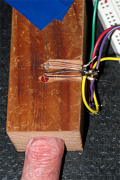
In Optical pulse monitor with little electronics  and Digital filters for pulse monitor, I developed an optical pulse monitor using an IR emitter, a phototransistor, 2 resistors, and an Arduino.  On Thursday, I decided to try to extend this to a pulse oximeter, by adding a red LED (and current-limiting resistor) as well.  Because excluding ambient light is so important, I decided to build a mount for everything out of a block of wood:

Short piece of 2×2 wood, with a 3/4″ diameter hole drilled with a Forstner bit partway through the block. Two 1/8″ holes drilled for 3mm LEDs on top, and one for a 3mm phototransistor on the bottom (lined up with the red LED). Wiring channels were cut with the same 1/8″ drill bit, and opened up a with a round riffler. Electrical tape holds the LEDs and phototransistor in place (removed here to expose the diodes).

My first test with the new setup was disappointing.  The signal from the IR LED swamped out the signal from the red LED, being at least 4 times as large. The RC discharge curves for the phototransistor for the IR signal was slow enough that I would have had to go to a very low sampling rate to see the red LED signal without interference from the discharge from the IR pulse.  I could reduce the signal for the IR LED to only twice the red output by increasing the IR current-limiting resistor to 1.5kΩ, and reduce the RC time constant of the phototransistor by reducing the pulldown resistor for it to 100kΩ The reduction in the output of the IR LED and decreased sensitivity of the phototransistor made about a 17-fold reduction in the amplitude of the IR signal, and the red signal was about a thirtieth of what I’d previously been getting for the IR signal.  Since the variation in amplitude that made up my real signal was about 10 counts before, it is substantially less than 1 count now, and is  too small to be detected even with the digital filters that I used.

I could probably solve this problem of a small signal by switching from the Arduino to the KL25Z, since going from a 10-bit ADC to a 16-bit ADC would allow a 64 times larger signal-to-noise ratio (that is, +36dB), getting me back to enough signal to be detectable even with the reductions..  I’ve ordered headers from Digi-Key for the KL25Z, so next week I’ll be able to test this.

I did do something very stupid yesterday, though in a misguided attempt to fix the problem.  I had another red LED (WP710A10ID) that was listed on the spec sheet as being much brighter than the one I’d been using (WP3A8HD), so I soldered it in.  The LED was clearly much brighter, but when I put my finger in the sensor, I got almost no red signal!  What went wrong?

A moment’s thought explained the problem to me (I just wish I had done that thinking BEFORE soldering in the LED).  Why was the new LED brighter for the same current?  It wasn’t that the LED was more efficient at generating photons, but that the wavelength of the light was shorter, and so the eye was more sensitive to it.

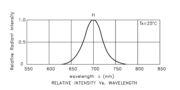
Spectrum of the WP3A8HD red LED that I first used. It has a peak at 700nm and dominant wavelength at 660nm. I believe that the “dominant wavelength” refers to the peak of the spectrum multiplied by the sensitivity of the human eye.  Spectrum copied from Kingbright preliminary specification for WP3A8HD.

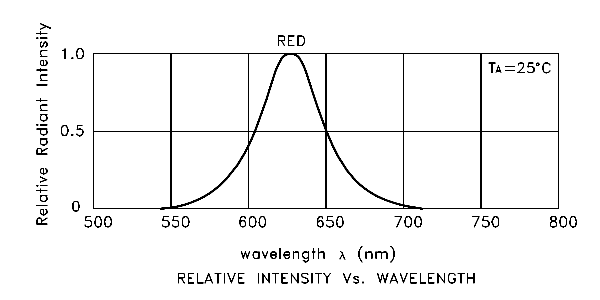
Spectrum of the WP710A10ID brighter red LED that didn’t work for me. The peak is at 627nm and the “dominant wavelength” is 617nm. The extra brightness is coming from this shorter wavelength, where the human eye is more sensitive. Image copied from the Kingbright spec sheet.

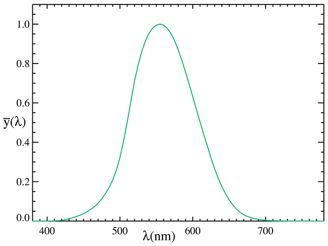
1931 CIE luminosity curve, representing a standardized sensitivity of the human eye with bright lighting (photopic vision). The peak is at 555nm. Note that there are better estimates of human eye sensitivity now available (see the discussion of newer ones in the Wikipedia article on the Luminosity function).
Image copied from Wikipedia.

The new LED is brighter, because the human eye is more sensitive to its shorter wavelength, but the optimum sensitivity of the phototransistor is at longer wavelengths, so the phototransistor is less sensitive to the new LED than to the old one.

Typical spectral sensitivity of a silicon photodiode or phototransistor. This curve does not take into account any absorption losses in the packaging of the part, which can substantially change the response. Note that the peak sensitivity is in the infrared, around 950nm, not in the green around 555nm as with the human eye. Unfortunately, Kingbright does not publish a spectral sensitivity curve for their WP3DP3B phototransistor, so this image is a generic one copied from https://upload.wikimedia.org/wikipedia/commons/4/41/Response_silicon_photodiode.svg

This sensitivity is much better matched to the IR emitter (WP710A10F3C) than to either of the red LEDs:

Spectrum for the WP710A10F3C IR emitter, copied from the Kingbright spec sheet. The peak is at 940nm with a 50nm bandwidth. There is no “dominant wavelength”, because essentially all the emissions are outside the range of the human eye.

Furthermore, blood and flesh is more opaque at the shorter wavelength, so I had more light absorbed and less sensitivity in the detector, making for a much smaller signal.

Scott Prahl’s estimate of oxyhemoglobin and deoxyhemoglobin molar extinction coefficients, copied from http://omlc.ogi.edu/spectra/hemoglobin/summary.gif
Tabulated values are available at http://omlc.ogi.edu/spectra/hemoglobin/summary.html and general discussion at http://omlc.ogi.edu/spectra/hemoglobin/
The higher the curve here the less light is transmitted. Note that 700nm has very low absorption (290), but 627nm has over twice as high an absorption (683).  Also notice that in the infrared

I had to go back to the red LED (WP3A8HD) that I started with. Here is an example of the waveform I get with that LED, dropping the sampling rate to 10Hz:

The green waveform is the voltage driving the red LED and through a 100Ω resistor. The red LED is on for the 1/30th of second that the output is low, then the IR LED is on (through a 1.5kΩ resistor) for 1/30th of a second, then both are off. THe yellow trace shows the voltage at the phototransistor emitter with a 680kΩ pulldown.
This signal seems to have too little amplitude for the variation to be detected with the Arduino (the scale is 1v/division with 0v at the bottom of the grid).

I can try increasing the signal by using 2 or more red LEDs (though the amount of current needed gets large), or I could turn down the IR signal to match the red signal and use an amplifier to get a big enough signal for the Arduino to read.  Sometimes it seems like a 4.7kΩ resistor on the IR emitter matches the output, and sometimes there is still much more IR signal received, depending on which finger I use and how I hold it in the device.

I was thinking of playing with some amplification, but I could only get a gain of about 8, and even then I’d be risking saturation of the amplifier.  I think I’ll wait until the headers come and I can try the KL25Z board—the gain of 64 from the higher resolution ADC is likely to be more useful.  If that isn’t enough, I can try adding gain also.  I could also eliminate the “off-state” and just amplify the difference between IR illumination and red illumination.  I wonder if that will let me detect the pulse, though.


Filed under: Circuits course, freshman design seminar Tagged: Arduino, biquad filter, digital filter, IIR filter, IR emitter, LED, phototransistor, pulse, pulse monitor, pulse oximeter

Failed attempt at pulse oximeter

In Optical pulse monitor with little electronics  and Digital filters for pulse monitor, I developed an optical pulse monitor using an IR emitter, a phototransistor, 2 resistors, and an Arduino.  On Thursday, I decided to try to extend this to a pulse oximeter, by adding a red LED (and current-limiting resistor) as well.  Because excluding ambient light is so important, I decided to build a mount for everything out of a block of wood:

Short piece of 2×2 wood, with a 3/4″ diameter hole drilled with a Forstner bit partway through the block. Two 1/8″ holes drilled for 3mm LEDs on top, and one for a 3mm phototransistor on the bottom (lined up with the red LED). Wiring channels were cut with the same 1/8″ drill bit, and opened up a with a round riffler. Electrical tape holds the LEDs and phototransistor in place (removed here to expose the diodes).

My first test with the new setup was disappointing.  The signal from the IR LED swamped out the signal from the red LED, being at least 4 times as large. The RC discharge curves for the phototransistor for the IR signal was slow enough that I would have had to go to a very low sampling rate to see the red LED signal without interference from the discharge from the IR pulse.  I could reduce the signal for the IR LED to only twice the red output by increasing the IR current-limiting resistor to 1.5kΩ, and reduce the RC time constant of the phototransistor by reducing the pulldown resistor for it to 100kΩ The reduction in the output of the IR LED and decreased sensitivity of the phototransistor made about a 17-fold reduction in the amplitude of the IR signal, and the red signal was about a thirtieth of what I’d previously been getting for the IR signal.  Since the variation in amplitude that made up my real signal was about 10 counts before, it is substantially less than 1 count now, and is  too small to be detected even with the digital filters that I used.

I could probably solve this problem of a small signal by switching from the Arduino to the KL25Z, since going from a 10-bit ADC to a 16-bit ADC would allow a 64 times larger signal-to-noise ratio (that is, +36dB), getting me back to enough signal to be detectable even with the reductions..  I’ve ordered headers from Digi-Key for the KL25Z, so next week I’ll be able to test this.

I did do something very stupid yesterday, though in a misguided attempt to fix the problem.  I had another red LED (WP710A10ID) that was listed on the spec sheet as being much brighter than the one I’d been using (WP3A8HD), so I soldered it in.  The LED was clearly much brighter, but when I put my finger in the sensor, I got almost no red signal!  What went wrong?

A moment’s thought explained the problem to me (I just wish I had done that thinking BEFORE soldering in the LED).  Why was the new LED brighter for the same current?  It wasn’t that the LED was more efficient at generating photons, but that the wavelength of the light was shorter, and so the eye was more sensitive to it.

Spectrum of the WP3A8HD red LED that I first used. It has a peak at 700nm and dominant wavelength at 660nm. I believe that the “dominant wavelength” refers to the peak of the spectrum multiplied by the sensitivity of the human eye.  Spectrum copied from Kingbright preliminary specification for WP3A8HD.

Spectrum of the WP710A10ID brighter red LED that didn’t work for me. The peak is at 627nm and the “dominant wavelength” is 617nm. The extra brightness is coming from this shorter wavelength, where the human eye is more sensitive. Image copied from the Kingbright spec sheet.

1931 CIE luminosity curve, representing a standardized sensitivity of the human eye with bright lighting (photopic vision). The peak is at 555nm. Note that there are better estimates of human eye sensitivity now available (see the discussion of newer ones in the Wikipedia article on the Luminosity function).
Image copied from Wikipedia.

The new LED is brighter, because the human eye is more sensitive to its shorter wavelength, but the optimum sensitivity of the phototransistor is at longer wavelengths, so the phototransistor is less sensitive to the new LED than to the old one.

Typical spectral sensitivity of a silicon photodiode or phototransistor. This curve does not take into account any absorption losses in the packaging of the part, which can substantially change the response. Note that the peak sensitivity is in the infrared, around 950nm, not in the green around 555nm as with the human eye. Unfortunately, Kingbright does not publish a spectral sensitivity curve for their WP3DP3B phototransistor, so this image is a generic one copied from https://upload.wikimedia.org/wikipedia/commons/4/41/Response_silicon_photodiode.svg

This sensitivity is much better matched to the IR emitter (WP710A10F3C) than to either of the red LEDs:

Spectrum for the WP710A10F3C IR emitter, copied from the Kingbright spec sheet. The peak is at 940nm with a 50nm bandwidth. There is no “dominant wavelength”, because essentially all the emissions are outside the range of the human eye.

Furthermore, blood and flesh is more opaque at the shorter wavelength, so I had more light absorbed and less sensitivity in the detector, making for a much smaller signal.

Scott Prahl’s estimate of oxyhemoglobin and deoxyhemoglobin molar extinction coefficients, copied from http://omlc.ogi.edu/spectra/hemoglobin/summary.gif
Tabulated values are available at http://omlc.ogi.edu/spectra/hemoglobin/summary.html and general discussion at http://omlc.ogi.edu/spectra/hemoglobin/
The higher the curve here the less light is transmitted. Note that 700nm has very low absorption (290), but 627nm has over twice as high an absorption (683).  Also notice that in the infrared

I had to go back to the red LED (WP3A8HD) that I started with. Here is an example of the waveform I get with that LED, dropping the sampling rate to 10Hz:

The green waveform is the voltage driving the red LED and through a 100Ω resistor. The red LED is on for the 1/30th of second that the output is low, then the IR LED is on (through a 1.5kΩ resistor) for 1/30th of a second, then both are off. THe yellow trace shows the voltage at the phototransistor emitter with a 680kΩ pulldown.
This signal seems to have too little amplitude for the variation to be detected with the Arduino (the scale is 1v/division with 0v at the bottom of the grid).

I can try increasing the signal by using 2 or more red LEDs (though the amount of current needed gets large), or I could turn down the IR signal to match the red signal and use an amplifier to get a big enough signal for the Arduino to read.  Sometimes it seems like a 4.7kΩ resistor on the IR emitter matches the output, and sometimes there is still much more IR signal received, depending on which finger I use and how I hold it in the device.

I was thinking of playing with some amplification, but I could only get a gain of about 8, and even then I’d be risking saturation of the amplifier.  I think I’ll wait until the headers come and I can try the KL25Z board—the gain of 64 from the higher resolution ADC is likely to be more useful.  If that isn’t enough, I can try adding gain also.  I could also eliminate the “off-state” and just amplify the difference between IR illumination and red illumination.  I wonder if that will let me detect the pulse, though.


Filed under: Circuits course, freshman design seminar Tagged: Arduino, biquad filter, digital filter, IIR filter, IR emitter, LED, phototransistor, pulse, pulse monitor, pulse oximeter

Digital filters for pulse monitor

In Optical pulse monitor with little electronics, I talked a bit about an optical pulse monitor using the Arduino and just 4 components (2 resistors, an IR emitter, and a phototransistor).  Yesterday, I had gotten as far as getting good values for resistors, doing synchronous decoding, and using a very simple low-pass IIR filter to clean up the noise.  The final result still had problems with the baseline shifting (probably due to slight movements of my finger in the sensor):

(click to embiggen) Yesterday’s plot with digital low-pass filtering, using y(t) = (x(t) + 7 y(t-1) )/8.  There is not much noise, but the baseline wobbles up and down a lot, making the signal hard to process automatically.

Today I decided to brush off my digital filter knowledge, which I haven’t used much lately, and see if I could design a filter using only small integer arithmetic on the Arduino, to clean up the signal more. I decided to use a sampling rate fs = 30Hz on the Arduino, to avoid getting any beating due to 60Hz pickup (not that I’ve seen much with my current setup). The 30Hz choice was made because I do two measurements (IR on and IR off) for each sample, so my actual measurements are at 60Hz, and should be in the same place in any noise waveform that is picked up. (Europeans with 50Hz line frequency would want to use 25Hz as their sampling frequency.)

With the 680kΩ resistor that I selected yesterday, the 30Hz sampling leaves plenty of time for the signal to charge and discharge:

The grid line in the center is at 3v. The green trace is the signal to on the positive side of the IR LED, so the LED is on when the trace is low (with 32mA current through the pullup resistor). The yellow trace is the voltage at the Arduino input pin: high when light is visible, low when it is dark. This recording was made with my middle finger between the LED and the phototransistor.

I decided I wanted to replace the low-pass filter with a passband filter, centered near 1Hz (60 beats per minute), but with a range of about 0.4Hz (24 bpm) to 4Hz (240bpm). I don’t need the passband to be particularly flat, so I decided to go with a simple 2-pole, 2-zero filter (called a biquad filter). This filter has the transfer function

To get the gain of the filter at a frequency f, you just compute , where .  Note that the z values that correspond to sinusoids are along the unit circle, from DC at up to the Nyquist frequency at .

The filter is implemented as a simple recurrence relation between the input x and the output y:

This is known as the “direct” implementation.  It takes a bit more memory than the “canonical” implementation, but has some nice properties when used with small-word arithmetic—the intermediate values never get any further from 0 than the output and input values, so there is no overflow to worry about in intermediate computations.

I tried using an online web tool to design the filter http://www-users.cs.york.ac.uk/~fisher/mkfilter/, and I got some results but not everything on the page is working.  One can’t very well complain to Tony Fisher about the maintenance, since he died in 2000. I tried using the tool at http://digitalfilter.com/enindex.html to look at filter gain, but it has an awkward x-axis (linear instead of logarithmic frequency) and was a bit annoying to use.  So I looked at results from Tony Fisher’s program, then used my own gnuplot script to look at the response for filter parameters I was interested in.

The filter program gave me one obvious result (that I should not have needed a program to realize): the two zeros need to be at DC and the Nyquist frequency—that is at ±1.  That means that the numerator of the transfer function is just , and b0=1, b1=0, and b2=–1.  The other two parameters it gave me were a2=0.4327386423 and a1=–1.3802466192.  Of course, I don’t want to use floating-point arithmetic, but small integer arithmetic, so that the only division I do is by powers of 2 (which the compiler turns into a quick shift operation).

I somewhat arbitrarily selected 32 as my power of 2 to divide by, so that my transfer function is now

and my recurrence relation is

with A1 and A2 restricted to be integers.  Rounding the numbers from Fisher’s program suggested A1=-44 and A2=14, but that centered the filter at a bit higher frequency than I liked, so I tweaked the parameters and drew plots to see what the gain function looked like.  I made one serious mistake initially—I neglected to check that the two poles were both inside the unit circle (they were real-valued poles, so the check was just applying the quadratic formula).  My first design (not the one from Fisher’s program) had one pole outside the unit circle—it looked fine on the plot, but when I implemented it, the values grew until the word size was exceeded, then oscillated all over the place.  When I realized what was wrong, I checked the stability criterion and changed the A2 value to make the pole be inside the unit circle.

I eventually ended up with A1=-48 and A2=17, which centered the filter at 1, but did not have as high an upper frequency as I had originally thought I wanted:

(click to embiggen) The gain of the filter that I ended up implementing has -3dB points at about 0.43 and 2.15 Hz.

Here is the gnuplot script I used to generate the plot—it is not fully automatic (the xtics, for example, are manually set). Click it to expand.

fs = 30	# sampling frequency
A0=32.  # multiplier (use power of 2)
b=16.

A1=-(A0+b)
A2=b+1

peak = fs/A0	# approx frequency of peak of filter

set title sprintf("Design of biquad filter, fs=%3g Hz",fs)

set key bottom center
set ylabel "gain [dB]"
unset logscale y
set yrange [-20:30]

set xlabel "frequency [Hz]"
set logscale x
set xrange [0.01:0.5*fs]

set xtics add (0.43, 2.15)
set grid xtics

j=sqrt(-1)
biquad(zinv,b0,b1,b2,a0,a1,a2) = (b0+zinv*(b1+zinv*b2))/(a0+zinv*(a1+zinv*a2))
gain(f,b0,b1,b2,a0,a1,a2) = abs( biquad(exp(j*2*pi*f/fs),b0,b1,b2,a0,a1,a2))
phase(f,b0,b1,b2,a0,a1,a2) = imag(log( biquad(exp(j*2*pi*f/fs),b0,b1,b2,a0,a1,a2)))

plot 20*log(gain(x,A0,0,-A0,  A0,A1,A2)) \
		title sprintf("%.0f (1-z^-2)/(%.0f+ %.0f z^-1 + %.0f z^-2)", \
			A0, A0, A1, A2), \
	20*log(gain(peak,A0,0,-A0,  A0,A1,A2))-3 title "approx -3dB"

I wrote a simple Arduino program to sample the phototransistor every 1/60th of a second, alternating between IR off and IR on. After each IR-on reading, I output the time, the difference between on and off readings, and the filtered difference. (click on the code box to view it)

#include "TimerOne.h"

#define rLED 3
#define irLED 5

// #define CANONICAL   // use canonical, rather than direct implementation of IIR filter
// Direct implementation seems to avoid overflow better.
// There is probably still a bug in the canonical implementation, as it is quite unstable.

#define fs (30) // sampling frequency in Hz
#define half_period (500000L/fs)  // half the period in usec

#define multiplier  32      // power of 2 near fs
#define a1  (-48)           // -(multiplier+k)
#define a2  (17)            // k+1

volatile uint8_t first_tick;    // Is this the first tick after setup?
void setup(void)
{
    Serial.begin(115200);
//    pinMode(rLED,OUTPUT);
    pinMode(irLED,OUTPUT);
//    digitalWrite(rLED,1);  // Turn RED LED off
    digitalWrite(irLED,1); // Turn IR LED off

    Serial.print("# bandpass IIR filter\n# fs=");
    Serial.print(fs);
    Serial.print(" Hz, period=");
    Serial.print(2*half_period);
    Serial.print(" usec\n#  H(z) = ");
    Serial.print(multiplier);
    Serial.print("(1-z^-2)/(");
    Serial.print(multiplier);
    Serial.print(" + ");
    Serial.print(a1);
    Serial.print("z^-1 + ");
    Serial.print(a2);
    Serial.println("z^-2)");
#ifdef CANONICAL
    Serial.println("# using canonical implementation");
#else
    Serial.println("# using direct implementation");
#endif
    Serial.println("#  microsec raw   filtered");

    first_tick=1;
    Timer1.initialize(half_period);
    Timer1.attachInterrupt(half_period_tick,half_period);
}

#ifdef CANONICAL
// for canonical implementation
 volatile int32_t w_0, w_1, w_2;
#else
// For direct implementation
 volatile int32_t x_1,x_2, y_0,y_1,y_2;
#endif

void loop()
{
}

volatile uint8_t IR_is_on=0;    // current state of IR LED
volatile uint16_t IR_off;       // reading when IR is off (stored until next tick)

void half_period_tick(void)
{
    uint32_t timestamp=micros();

    uint16_t IR_read;
    IR_read = analogRead(0);
    if (!IR_is_on)
    {   IR_off=IR_read;
        digitalWrite(irLED,0); // Turn IR LED on
        IR_is_on = 1;
        return;
    }

    digitalWrite(irLED,1); // Turn IR LED off
    IR_is_on = 0;

    Serial.print(timestamp);
    Serial.print(" ");

    int16_t x_0 = IR_read-IR_off;
    Serial.print(x_0);
    Serial.print(" ");

 #ifdef CANONICAL
    if (first_tick)
    {  // I'm not sure how to initialize w for the first tick
       w_2 = w_1 = multiplier*x_0/ (1+a1+a2);
       first_tick = 0;
    }
 #else
    if (first_tick)
    {   x_2 = x_1 = x_0;
        first_tick = 0;
    }
#endif

#ifdef CANONICAL
    w_0 = multiplier*x_0 - a1*w_1 -a2*w_2;
    int32_t y_0 = w_0 - w_2;
    Serial.println(y_0);
    w_2=w_1;
    w_1=w_0;
#else
     y_0 = multiplier*(x_0-x_2) - a1*y_1 -a2*y_2;
     Serial.println(y_0);
     y_0 /= multiplier;
     x_2 = x_1;
     x_1 = x_0;
     y_2 = y_1;
     y_1 = y_0;
#endif
}

Here are a couple of examples of the input and output of the filtering:

(click to embiggen) The input signals here are fairly clean, but different runs often get quite different amounts of light through the finger, depending on which finger is used and the alignment with the phototransistor. Note that the DC offset shifts over the course of each run.

(click to embiggen) After filtering the DC offset and the baseline shift are gone. The two very different input sequences now have almost the same range. There is a large, clean downward spike at the beginning of each pulse.

Overall, I’m pretty happy with the results of doing digital filtering here. Even a crude 2-zero, 2-pole filter using just integer arithmetic does an excellent job of cleaning up the signal.


Filed under: Circuits course, Data acquisition, freshman design seminar Tagged: Arduino, biquad filter, digital filter, IIR filter, IR emitter, LED, phototransistor, pulse, pulse monitor, pulse oximeter