Optical pulse monitor with little electronics
In yesterday’s blog post, I talked mainly about what my son did with his time yesterday, to mention the small amount of debugging help I gave him. Today I’ll post about what I did with most of my time yesterday.
This year, I am hoping to lead a 2-unit freshman design seminar for bioengineering students. (Note: I did not say “teach” here, as I’m envisioning more of a mentoring role than a specific series of exercises.) One thing I’m doing is trying to come up with design projects that freshmen with essentially no engineering skills can do as a team. They may have to learn something new (I certainly hope they do!), but they should only spend a total of 60 hours on the course, including class time. Since I want to spend some of class time on lab tours, lab safety, using the library resources, and how to work in a group effectively, there is not a lot of time left for the actual design and implementation.
One of the things I found very valuable in designing the Applied Circuits course was doing all the design labs myself, sometimes several times, in order to tweak the specs and anticipate where the students would have difficulty. I expect to do some redesign of a couple of the circuits labs this year, but that course is scheduled for Spring (and finally got official approval this week), while the (not yet approved) freshman seminar is scheduled for Winter. So I’m now experimenting with projects that I think may be suitable for the freshman design seminar.
These students cannot individually be expected to know anything useful, high school in California being what it is. As a group, though, I think I can expect a fair amount of knowledge of biology, chemistry, and physics, with perhaps a sprinkling of math and computer programming. I can’t expect any electronics knowledge, and we won’t have access to a machine shop—we may get permission for the students to use a laser cutter under supervision. We can probably get some space in an electronics lab, but maybe not in a bio lab (the dean took away the department’s only teaching lab, with a “promise” to build a bigger one—but it is unlikely to be available for the freshmen by Winter quarter—I miss our first dean of engineering, as we seem to have had a series of incompetent deans since then).
So I’m looking for projects that can essentially be built at home with minimal tools and skills, but that are interesting enough to excite students to continue to higher levels in the program. And I want them to be design projects, not kit-building or cookbook projects, with multiple possible solutions.
So far, there have been a couple of ideas suggested, both involving a small amount of electronics and some mechanical design:
- An optical growth meter for continuously monitoring a liquid culture of bacteria or yeast. The electronics here is just a light source (LED or laser diode with current-limiting resistor), a phototransistor, a current-to-voltage converter for the phototransistor (one resistor), and a data logger (like the Arduino Data Logger we use for the circuits course). The hard part is coming up with a good way to get uniform sampling of the liquid culture while it is in an incubator on a shaker table. There are lots of possible solutions: mounting stuff around flasks, immersed sensors, bending glass tubing so that the swirling culture is pumped through the tubes, external peristaltic pumps, … . Design challenges include how the parts of the apparatus that touch the culture will be sterilized, how to keep things from falling apart when they are shaken for a couple of days, and so forth. I’ve not even started trying to do a design here, though I probably should, as the mechanical design is almost all unfamiliar to me, and I’d be a good example of the cluelessness that the students would bring to the project.
- An optical pulse sensor or pulse oximeter. This is the project I decided to work on yesterday. The goal is to shine light through a finger and get a good pulse signal. (I tried this last summer, making a very uncomfortable ear clip and doing a little testing before rejecting the project for the circuits course.) If I can get good pulse signals from both red and IR light sources, I should be able to take differences or ratios and get an output proportional to blood oxygenation.
I decided yesterday to try to build a pulse monitor with almost no electronics. In particular, I wanted to try building without an op amp or other amplifier, feeding the phototransistor signal directly into an Arduino analog in. (I may switch to using the KL25Z for this project, as the higher resolution on the analog-to-digital converter means I could use smaller signals without amplification.)
A phototransistor is essentially a light-to-current converter. The current through the phototransistor is essentially linear in the amount of light, over a pretty wide range. The Arduino analog inputs are voltage sensors, so we need to convert the current to a voltage. The simplest way to do this is to put a series resistor to ground, and measure the voltage across the series resistor. The voltage we see is then the current times the resistance. Sizing the resistor is a design task—how big a current do we get with the intensity of light through the finger, and how much voltage do we need. The voltage needed can be estimated from the resolution of the analog-to-digital converter, but the amount of light is best measured empirically.
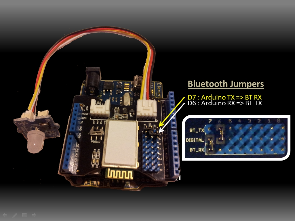
One problem that the pulse monitor faces is huge variations in ambient light. Ideally the phototransistor gets light only from LED light shining through the finger, but that is a bit hard to set up while breadboarding. Distinguishing the ambient light from the light through the finger can be difficult. Yesterday, I tried to reduce that problem by using “synchronous decoding”. That is, I turned the LED on and off, and measured the difference between the phototransistor current with the LED on and with the LED off. Using the Arduino to control the LED as well as to read the voltage is fairly easy—these are the sorts of tasks that are starter projects on the Arduino, so should be within the capabilities of the freshmen (with some learning on their part).
I also looked at the phototransistor output with my BitScope oscilloscope, so that I could see the waveform that the Arduino was sampling two points from. Here is an example waveform:
The x-axis is 20ms/division, and the y-axis 1v/division, with the center line at 2v.
I put in a 50% duty cycle (20ms on, 20ms off). The IR light is shining through my index finger.
For the above trace, I used a 680kΩ pulldown resistor to convert the current to voltage. I played a lot with different resistors yesterday, to get a feel for the tradeoffs. Such a large resistor provides a large voltage swing for a small change in current, but the parasitic capacitance makes for rather slow RC charge/discharge curves. Using larger resistors does not result in larger swings (unless the frequency of the input is reduced), because the RC time constant gets too large and the slowly changing signal does not have time to make a full swing. I tried, as an experiment, adding a unity-gain buffer, so that the BitScope and Arduino inputs would not be loading the phototransistor. This did not make much difference, so most of the parasitic capacitance is probably in the phototransistor itself. One can get faster response for a fixed change in light only by decreasing the voltage swing, which would then require amplification to get a big enough signal to be read by the Arduino. (It may be that the extra 6 bits of resolution on the KL25Z board would allow a resistor as low as 20kΩ and much faster response.)
Note that ambient light results in a DC shift of the waveform without a change in shape, until it gets bright enough that the current is more than 5v/680kΩ (about 7µA), at which point the signal gets clipped. Unfortunately, ordinary room lighting is enough to saturate the sensor with this large a series resistor. I was able to get fairly consistent readings by using the clothespin ear clip I made last summer, clamped open to make it the right size for my finger. I did even better when I put the clip and my hand into a camera bag that kept out most of the ambient light. Clearly, mechanical design for eliminating ambient light will be a big part of this design.
One might think that the 2v signal seen on the BitScope is easily big enough for pulse detection, but remember that this is not the signal we are interested in. The peak-to-peak voltage is proportional to how transparent the finger is—we are interested in the variation of that amplitude with blood flow. Here is an example plot of the sort of signal we are looking at:

(click to embiggen) The pulse here is quite visible, but is only about a 15–30 count change in the 300-count amplitude signal. Noise from discretization (and other sources) makes the signal hard to pick out auotmatically. This signal was recorded with the Arduino data logger, but only after I had modified the data logger code to turn the IR emitter on and off and report differences in the readings rather than the readings themselves. Note the sharp downward transition (increased opacity due to more blood) at the beginning of each pulse.
To get a bigger, cleaner signal, I decided to do some very crude low-pass filtering on the Arduino. I used the simplest of infinite-impulse response (IIR) filters: 
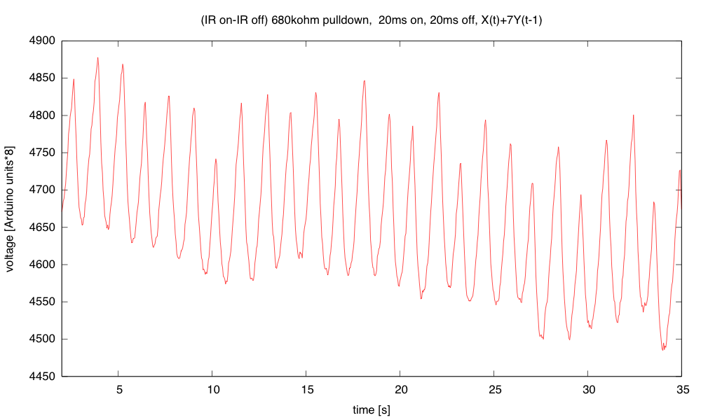
(click to embiggen) With digital low-pass filtering, the pulse signal is much cleaner, but the sharp downward transition at the start of each pulse has been rounded off by the filter. This data was not captured with the Arduino Data Logger, but by cutting and pasting from the Arduino serial monitor, which involves simpler (hence more feasible for freshmen) programming of the Arduino.
I now have a very clean pulse signal, using just the Arduino, an IR emitter, a phototransistor, and two resistors. There is still a huge offset, as the signal is 200 counts out of 4600, and the offset fluctuates slowly. To get a really good signal, I’d want to do a bandpass filter that passes 0.3Hz to 3Hz (20bpm–200bpm), but designing that digital filter would be beyond the scope of a freshman design seminar. Even the simple IIR filter is pushing a bit here.
I’m not sure how to go from here to the pulse oximeter (using both an IR and a red LED) without fancy digital filtering. Here is the circuit so far:

Although the 120Ω resistor allows up to 32mA, I didn’t believe that the Arduino outputs could actually sink that much current—20 mA is what the spec sheet allows. Checking with the BitScope, I see a 3840mV drop across the resistor, for 32mA. Note: I used pins D3 and D5 of the Arduino so that I could use pulse-width modulation (PWM) if I wanted to. (Schematic drawn with Digikey’s SchemeIt.)
Filed under: Circuits course, Data acquisition, freshman design seminar Tagged: Arduino, IR emitter, LED, phototransistor, pulse, pulse monitor, pulse oximeter


 . Because division is very slow on the Arduino, I limited myself to simple shifts for division: a= 1/2, 1/4, or 1/8. To avoid losing even more precision, I actually output
  then divided by 8 to get Y(t). I also used a 40msec sampling period, with the IR emitter on for 20ms, then off for 20msec (the waveform shown in the oscilloscope trace above).