Posts with «optocoupler» label

Less Rock, More Roll: A MIDI Barrel Piano

Strolling around a park, pedestrian zone, or tourist area in any bigger city is rarely complete without encountering the sound of a barrel organ — the perfect instrument if arm stamina and steady rotation speed are your kind of musical skills. Its less-encountered cousin, and predecessor of self-playing pianos, is the barrel piano, which follows the same playing principle: a hand-operated crank rotates a barrel, and either pins located on that barrel, or punched paper rolls encode the strings it should pluck in order to play its programmed song. [gabbapeople] thought optocouplers would be the perfect alternative here, and built a MIDI barrel piano with them.

Keeping the classic, hand-operated wheel-cranking, a 3D-printed gear mechanism rolls a paper sheet over a plexiglas fixture, but instead of having holes punched into it, [gabbapeople]’s piano has simple markings printed on them. Those markings are read by a set of Octoliner modules mounted next to each other, connected to an Arduino. The Octoliner itself has eight pairs of IR LEDs and phototransistors arranged in a row, and is normally used to build line-following robots, so reading note markings is certainly a clever alternative use for it.

Each LED/transistor pair represents a dedicated note, and to prevent false positives from neighboring lines, [gabbapeople] 3D printed little collars to isolate each of the pairs. Once the signals are read by the Arduino, they’re turned into MIDI messages to send via USB to a computer running any type of software synthesizer. And if your hands do get tired, you can also crank it with a power drill, as shown in the video after the break, along with a few playback demonstrations.

It’s always fun to see a modern twist added to old-school instruments, especially the ones that aren’t your typical MIDI controllers, like a harp, a full-scale church organ, or of course the magnificently named hurdy-gurdy. And for more of [gabbapeople]’s work, check out his split-flip weather display.


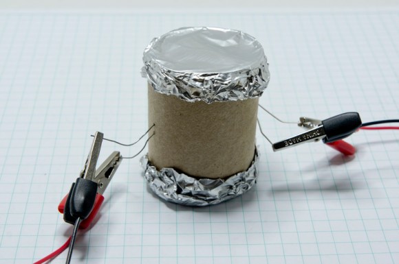
MacGyvered Optoisolator is a Great Introduction

Sometimes the best way to learn about a technology is to just build something yourself. That’s what [Dan] did with his DIY optoisolator. The purpose of an optoisolator is to allow two electrical systems to communicate with each other without being electrically connected. Many times this is done to prevent noise from one circuit from bleeding over into another.

[Dan] built his incredibly simple optoisolator using just a toilet paper tube, some aluminum foil, an LED, and a photo cell. The electrical components are mounted inside of the tube and the ends of the tube are sealed with foil. That’s all there is to it. To test the circuit, he configured an Arduino to send PWM signals to the LED inside the tube at various pulse widths. He then measured the resistance on the other side and graphed the resulting data. The result is a curve that shows the LED affects the sensor pretty drastically at first, but then gets less and less effective as the frequency of the signal increases.

[Dan] then had some more fun with his project by testing it on a simple temperature controller circuit. An Arduino reads a temperature sensor and if the temperature rises above a certain value, it turns on a fan to cool the sensor off again. [Dan] first graphed the sensor data with no fan hooked up. He only used ambient air to cool things down. The resulting graph is a pretty smooth curve. Next he hooked the fan up and tried again. This time the graph went all kinds of crazy. Every time the fan turned on, it created a bunch of electrical noise that prevented the Arduino from getting an accurate analog reading of the temperature sensor.

The third test was to remove the motor circuit and move it to its own bread board. The only thing connecting the Arduino circuit to the fan was a wire for the PWM signal and also a common ground. This smoothed out the graph but it was still a bit… lumpy. The final test was to isolate the fan circuit from the temperature sensor and see if it helped the situation. [Dan] hooked up his optoisolator and tried again. This time the graph was nice and smooth, just like the original graph.

While this technology is certainly not new or exciting, it’s always great to see someone learning by doing. What’s more is [Dan] has made all of his schematics and code readily available so others can try the same experiment and learn it for themselves.


Filed under: Arduino Hacks

Can I Control a Servo via PWM from an Optocoupler

Question: Is it possible to control this hobby servo using a PWM signal from Arduino via this optocoupler to the servo?

read more