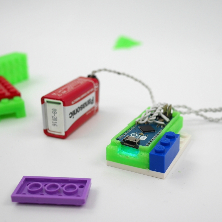
Posts with «ir» label

A Remote for CHDK Cameras Made Possible with Arduino

[AlxDroidDev] built himself a nice remote control box for CHDK-enabled cameras. If you haven’t heard of CHDK, it’s a pretty cool software modification for some Canon cameras. CHDK adds many new features to inexpensive cameras. In this case, [AlxDroidDev] is using a feature that allows the camera shutter to be activated via USB. CHDK can be run from the SD card, so no permanent modifications need to be made to the camera.

[AlxDroidDev’s] device runs off of an ATMega328p with Arduino. It operates from a 9V battery. The circuit contains an infrared receiver and also a Bluetooth module. This allows [AlxDroidDev] to control his camera using either method. The device interfaces to the camera using a standard USB connector and cable. It contains three LEDs, red, green, and blue. Each one indicates the status of a different function.

The Arduino uses Ken Shirrif’s IR Remote library to handle the infrared remote control functions. SoftwareSerial is used to connect to the Bluetooth module. The Arduino code has built-in functionality for both Canon and Nikon infrared remote controls. To control the camera via Bluetooth, [AlxDroidDev] built a custom Android application. The app can not only control the camera’s shutter, but it can also control the level of zoom.


Filed under: Arduino Hacks

Make a 3D printed LEGO-compatible Arduino Micro casing

Here we are after winter break with a new tutorial on 3d printing with Arduino Materia 101. The 5-step tutorial allows you to design a Lego-compatible case for the Arduino Micro to be used together with the power function IR-receiver mentioned in this other Tutorial.

During the lesson you’ll learn also how to make the Lego-compatible pieces accurately and easily with FreeCAD without taking all the measurements!

Follow the steps and print yours >>

Check the previous tutorials on 3d printing with Material 101

Interested in getting in touch and showing your experiments? Join Kristoffer on the Arduino forum dedicated to Materia 101 and give us your feedback.

Recently Arduino user Botberg implemented an auto-levelling bed sensor  to be  sure that the placement of the first extrusion layer is placed well and increasing the printer successes!

Smart Remote Control Doubles as Super Simple IR Sniffer

Want to sniff a remote control or other IR device's control codes? The Smart Remote Control will make quick work of that, combining an Arduino Yún with a simple solderless breadboard circuit.

Read more on MAKE

New Project: Smart Remote Control

Combine the Arduino Yún with a simple solderless breadboard circuit to create a homemade 'universal' remote control that you can navigate with your laptop or smartphone.

Read more on MAKE

Bare Bones Arduino IR Receiver

Old infrared remote controls can be a great way to interface with your projects. One of [AnalysIR's] latest blog posts goes over the simplest way to create an Arduino based IR receiver, making it easier than ever to put that old remote to good use.

Due to the popularity of their first IR receiver post, the silver bullet IR receiver, [AnalysIR] decided to write a quick post about using IR on the Arduino. The part list consists of one Arduino, two resistors, and one IR emitter. That’s right, an emitter. When an LED (IR or otherwise) is reverse biased it can act as a light sensor. The main difference when using this method is that the IR signal is not inverted as it would normally be when using a more common modulated IR receiver module. All of the Arduino code you need to get up and running is also provided. The main limitation when using this configuration, is that the remote control needs to be very close to the IR emitter in order for it to receive the signal.

What will you control with your old TV remote? It would be interesting to see this circuit hooked up so that a single IR emitter can act both as a transmitter and a receiver. Go ahead and give it a try, then let us know how it went!


Filed under: Arduino Hacks

Pair of musical hacks use sensor arrays as keyboards

This pair of musical keyboard hacks both use light to detect inputs. The pair of tips came in on the same day, which sparks talk of consipiracy theory here at Hackaday. Something in the weather must influence what types of projects people take on because we frequently see trends like this one. Video of both projects is embedded after the jump.

On the left is a light-sensitive keyboard which [Kaziem] is showing off. In this image he’s rolling a marble around on the surface. As it passes over the Cadmium Sulfide sensors (which are arranged in the pattern of white and black keys from a piano keyboard) the instrument plays pitches based on the changing light levels. [Thanks Michael via Make]

To the right is [Lex's] proximity sensor keyboard. It uses a half-dozen Infrared proximity sensor which pick up reflected light. He calls it a ‘quantised theremin’ and after seeing it in action we understand why. The overclocked Raspberry Pi playing the tones reacts differently based on distance from the keyboard itself, and hand alignment with the different sensors.


Filed under: musical hacks

Analog IR Temperature gauge


Introduction:
The IRTEMP module from Freetronics is an infrared remote temperature sensor that can be incorporated into your Arduino / microcontroller projects. It can scan a temperature between -33 to +220 C, and can be operated using a 3.3 to 5V power supply. It can be powered directly from the Arduino 5V pin.  This module can also provide an ambient temperature reading if required.
The Servo used in this project is a SG-5010 standard servo which will be utilised to display the temperature reading from the IRTEMP module.


Parts Required:
Freetronics Eleven or any compatible Arduino.
Freetronics IRTEMP module
MG-995  or SG-5010 Standard servo
Mini Breadboard 4.5cm x 3.5cm
Protoshieldand female header pins (not essential - but makes it more tidy)
9V Battery and Battery Clip
Wiresto connect it all together

Gauge parts:
Paper (to print the face of the gauge), and some glue to stick it to the wood.
MDF Standard panel (3mm width) - for the top and base of the gauge.
Galvanized bracket (25x25x40mm)
Timber screws: Hinge-long threads csk head Phillips drive (4G x 12mm)
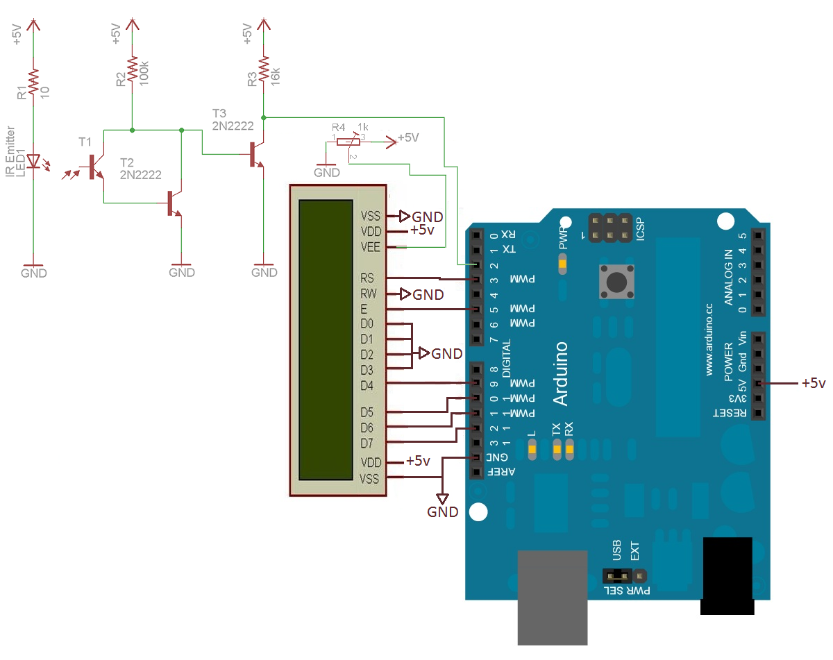


The Video:


The Arduino Sketch:


     The above sketch was created using Fritzing.


Arduino Code:
You can download the Arduino IDE from this site.

The IRTemp gauge requires a driver library to be installed into the Arduino IDE.
The latest IRTemp driver library can be found here.

 1
2
3
4
5
6
7
8
9
10
11
12
13
14
15
16
17
18
19
20
21
22
23
24
25
26
27
28
29
30
31
32
33
34
35
36
37
38
39
40
41
42
43
44
45
46
47
48
49
50
51
52
53
54
55
56
57
58
59
60
61
62
63
64
65
66
67
68
69
70
71
72
73
74
75
76
77
78
79
80
81
82
83
84
/* -------------------------------------------------------
Analog IR Temperature Gauge: written by ScottC on 1st Dec 2012.
http://arduinobasics.blogspot.com/2012/12/arduino-basics-analog-ir-temperature.html


* Some of the code was adapted from a sketch by Andy Gelme (@geekscape)
* For more information on using the IRTEMP
see www.freetronics.com/irtemp

* IRTemp library uses an Arduino interrupt:
* If PIN_CLOCK = 2, then Arduino interrupt 0 is used
* If PIN_CLOCK = 3, then Arduino interrupt 1 is used
---------------------------------------------------------*/

#include "IRTemp.h"
#include <Servo.h>

Servo servo1;
static const byte PIN_DATA = 2;
static const byte PIN_CLOCK = 3; // Must be either pin 2 or pin 3
static const byte PIN_ACQUIRE = 4;

static const bool SCALE=false; // Celcius: false, Farenheit: true

/* Used to capture the temperature from the IRTEMP sensor */
float irTemperature;
int temp;

/* The minimum and maximum temperatures on the gauge. */
static const int minTemp = -45;
static const int maxTemp = 135;


/* The servo minimum and maximum angle rotation */
static const int minAngle = 0;
static const int maxAngle = 175;
int servoPos;

IRTemp irTemp(PIN_ACQUIRE, PIN_CLOCK, PIN_DATA);


/*----------------------SETUP----------------------*/

void setup(void) {

servo1.attach(9); // turn on servo
}


/*-----------------------LOOP-----------------------*/

void loop(void) {
irTemperature = irTemp.getIRTemperature(SCALE);
printTemperature("IR", irTemperature);

/* If you want the ambient temperature instead - then use the code below. */
//float ambientTemperature = irTemp.getAmbientTemperature(SCALE);
//printTemperature("Ambient", ambientTemperature);

}

/*-----------printTemperature function---------------*/

void printTemperature(char *type, float temperature) {

temp=(int) temperature;
servoPos = constrain(map(temp, minTemp,maxTemp,minAngle,maxAngle),minAngle,maxAngle);

if (isnan(temperature)) {
//is not a number, do nothing
}
else {

/* To test the minimum angle insert the code below */
//servoPos = minAngle;

/*To test the maximum angle, insert the code below */
//servoPos = maxAngle;

/* Rotate servo to the designated position */
servo1.write(servoPos);
}
}

The code above was formatted using hilite.me

Notes:
Ambient temperature: If you want to get the ambient temperature from the IRTEMP module, then have a look at lines 58-59.
Servo Angles: You will notice on line 36, the maximum servo angle used was 175. This value was obtained through trial and error (see below).

Calibrating the servo angles
You may need to calibrate your servo in order to move through an angle of 0 to 180 degrees without straining the motor.Change the minAngle on line 35to a safe value (for example: 10), and the maxAngle on line 36 to a value like 170. Remove the comment tag (//) on line 76, and then run the sketch. Lower the minAngle until it reaches the minimum value on the gauge, making sure that the servo doesn't sound like it is straining to keep it in position.

Add the comment tag (//) back in, and then take out the comment tag for line 79. And follow a similar process, until you reach the maximum value on the gauge. Once again, make sure that the servo is not making a straining noise to hold it at that value. Make sure to add the comment tag back in, when you have finished the calibration.

In this example, the servo's minAngle value was 0, and maxAngle value was 175 after calibration, however, as you can see from the video, the physical range of the servo turned out to be 0 to 180 degrees.


The Temperature Gauge Picture

The following gauge was created in Microsoft Excel using an X-Y chart.  Data labels were manually repositioned in order to get the desired numerical effect.


Voice controlled TV

As seen in the picture there is an Arduino Uno with a protoshield on top with an IR receiver and IR LED. I undertook this project to learn how we used infra red light to control everyday devices and why it was used so often. I found that the process behind it is actually quite simple and I now have a better understanding of what is happening in the invisible infra red world. The basis of the code was taken from adafruit as this is where I mainly learnt how it all worked.

read more

A simple Arduino-based tachometer


Chris, from PyroElectro.com, proposes a comprehensive tutorial on how to make a simple, yet effective, Arduino-based tachometer.
The circuit is very simple: an IR led is coupled with an IR phototransistor to detect possible interruptions of the light beam, while the Arduino is responsible to calculate the time interval between two such events. Finally, a LCD is used to display the current RPM to the user.
To validate his project, a typical computer fan has been used in the set-up and the outcomes have demonstrated to be very close to the true RPM value (2600 +/- 100 RPMs).
The bill of materials, as well as the schematic, the source code and a detailed tutorial on how to build the circuit is available here.

[Via: PyroElectro.com]


Arduino Blog 06 Sep 20:10

Fighting over the Frat’s TV remote

[Colin Bookman] lives in a Fraternity house and apparently the remote for the cable box has a way of walking off. He figured out a method to give everyone control of the TV channel in one form or another.

The cable box can be seen perched on that shelf, and [Colin's] addition is the wooden box sitting on the floor. Inside is an Arduino board, and the cable snaking out of the enclosure is an IR LED. This give the Arduino the ability to send remote control commands to the TV box. The two arcade buttons on the front will switch the channel up or down.

But this is hardly a remote control replacement since you have to get up to use it, so he went a few steps further. The Arduino board was paired with an Ethernet shield. It serves up a web page that has a virtual keypad. So anyone with a smart phone or laptop can log into the server and start changing the channels. We’re not sure if this provides relief from a missing remote, or promotes impromptu fist fights when brothers can’t agree on what to watch. It certainly opens up the possibility of long-distance trolling as you could be sitting in class and decide to change the channel to Lifetime every ten minutes or so.

If you don’t have an Ethernet shield handy we’ve seen a similar setup that uses Bluetooth instead the network.


Filed under: home entertainment hacks