New Project: S.M.A.R.T. Alarm Clock
 Combine the Arduino Yún with a TFT Touch Shield to assemble a homemade alarm clock that automatically sets alarms based on calendar events and even emails with the correct code word. And it looks cool too!

 Combine the Arduino Yún with a TFT Touch Shield to assemble a homemade alarm clock that automatically sets alarms based on calendar events and even emails with the correct code word. And it looks cool too!
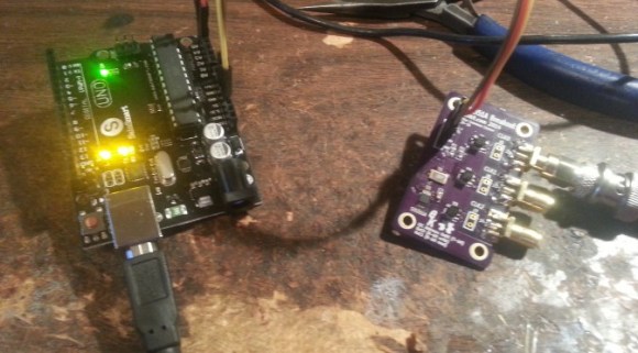
If you’re dealing with RF, you’ll probably have the need to generate a variety of clock signals. Fortunately, [Jason] has applied his knowledge to build a SI5351 library for the Arduino and a breakout board for the chip.
The SI5351 is a programmable clock generator. It can output up to eight unique frequencies at 8 kHz to 133 MHz. This makes it a handy tool for building up RF projects. [Jason]‘s breakout board provides 3 isolated clock outputs on SMA connectors. A header connects to an Arduino, which provides power and control over I2C.
If you’re looking for an application, [Jason]‘s prototype single-sideband radio shows the chip in action. This radio uses two of the SI5351 clocks: one for the VFO and one for the BFO. This reduces the part count, and could make this design quite cheap.
The Arduino library is available on Github, and you can order a SI5351 breakout board from OSHPark.


There are LED clocks, and then there are LED clocks that can blind you from 30 paces. [Stiggalicious's] LED ring clock is of the latter variety. 200 WS2812B/Neopixel RGB LEDs drive the ring clock to pupil searing levels. The clock runs on ATMega1284P, with timekeeping handled by an NXP PCF8563 real-time clock chip. Code is written in Arduino’s wiring language using Adafruit’s Neopixel library.
Building the clock with a single Printed Circuit Board (PCB) would be both expensive and wasteful. [Stiggalicious] cleverly designed his clock to be built with 8 copies of the same PCB. Each board makes up a 45° pie slice of the ring. All 8 PCBs have footprints for the CPU, clock chip, and other various discrete parts, but only the “master” section has these parts populated. 7 “slave” sections simply pass clock, data, power and ground through each LED. He used Seeedstudio’s board service to get 10 copies of his PCB made, just in case there were any mistakes.
[Stiggalicious] rolled the dice by buying exactly the 200 LEDs he needed. Either he got really lucky, or the WS2812 quality testing has improved, because only one LED had a dead blue LED.
If you’d like to find out more, [Stiggalicious] gives plenty of details in his Reddit thread. He doesn’t have a webpage setup for the clock but he’s uploaded his source code (pastebin link) and Altium schematic/PCB files (mega.nz link). We may be a bit biased, but hackaday.io would be a perfect spot for this or any other project!


Clocks have taken many forms of the years, starting with shadow clocks and sundials in Egypt around 3500 BC. Obviously, these could only tell the time while the sun was out. Water Clocks followed which could track time in the dark. Water Clocks are basically a bowl with a hole in the bottom. This bowl was set in a container filled with water. The water entered the bowl at a consistent rate and graduations on the inside of the bowl showed how much time had passed.
Mechanical clocks followed, as did quartz and the atomic clock. We have now entered a new era in time-telling, the Bamboo LED Clock. [Pascal] brings us this funky fresh chronometer all the way from Germany.
The front face is made from a bamboo pizza plate and gives the clock some modern minimalist pizzazz. A 1-meter long LED strip is attached to the circumference of the plate and contains 60 individually assignable RGB LED’s. An Arduino and Real Time Clock are responsible for the time keeping and coordination of the LED’s.
As you can see in the photo, 2 of the LED’s colors are used. The single red LED indicates the hour. The strip of blue LED’s show the minutes. If you’d like to build one of these [Pascal] has shared the Arduino code on his Instructables page.


Learn how to use MediaTek 3329-based GPS shields with Arduino in Chapter 19 of our Arduino Tutorials. The first chapter is here, the complete series is detailed here. If you have an EM406A GPS module, please visit the separate tutorial. Updated 15/01/2014
Introduction
In this instalment we will introduce and examine the use of the Global Positioning System receivers with Arduino systems. What is the GPS? In very simple terms, a fleet of satellites orbit the earth, transmitting signals from space. Your GPS receiver uses signals from these satellites to triangulate position, altitude, compass headings, etc.; and also receives a time and date signal from these satellites.
The most popular GPS belongs to the USA, and was originally for military use – however it is now available for users in the free world.
Interestingly, the US can switch off or reduce accuracy of their GPS in various regions if necessary, however many people tell me this is not an issue unless you’re in a combat zone against the US forces. For more information, have a look at Wikipedia or the USAF Space Command GPS Ops Centre site. As expected, other countries have their own GPS as well – such as Russia, China, and the EU is working on one as well.
So – how can us mere mortals take advantage of a multi-billion dollar space navigation system just with our simple Arduino? Easy – with an inexpensive GPS receiver and shield. In this tutorial we’ll use a GPS shield based on the MediaTek3329 GPS receiver from Tronixlabs.
Unlike the EM406A used in the other tutorial, the whole lot is all on one shield – and after some experimenting has better reception. Plus there’s an onboard SD card socket which we’ll use for a GPS logging device. The only catch is that you need to solder the stacking headers yourself. (update – if purchased from Tronixlabs these will be fully assembled):
![]()
Apart from the GPS shield we’ll also be using a typical Arduino-compatible LCD shield and of course an Arduino Uno or compatible. Finally before getting started, you need to set the two jumpers on the GPS shield as shown in the following image:
![]()
By doing this the serial data lines from the GPS receiver can be connected to Arduino D2 and D3 – which we will use with SoftwareSerial. The benefit of doing it this way is that you can then upload sketches without any hardware changes and also use the serial monitor and GPS at the same time. So let’s get started.
Testing your GPS shield
Simply connect your GPS shield as described above to your Arduino Uno or compatible, and upload the following sketch:
// Example 19.1

#include <SoftwareSerial.h>
SoftwareSerial GPS(2,3); // configure software serial port -

void setup()
{
  GPS.begin(9600);
  Serial.begin(9600);
}
void loop()
{
  byte a;
    if (GPS.available() > 0 )
  {
    a = GPS.read(); // get the byte of data from the GPS
    Serial.write(a);
  }
}
Note the use of SoftwareSerial in the sketch. As mentioned earlier, the GPS data is transferred to the Arduino via D2/D2 – which we set up as a software serial port.
If possible try to get your hardware close to a window, then open the serial monitor window. The first time you power up your receiver, it may take a minute or so to lock onto the available satellites, this period of time is the cold start time.
The subsequent times you power it up, the searching time is reduced somewhat as our receiver stores some energy in a supercap (very high-value capacitor) to remember the satellite data, which it will use the next time to reduce the search time (as it already has a “fair idea” where the satellites are).
Moving on, after a few moments you should be presented with a scrolling wall of text, for example:

What on Earth does all that mean? For one thing the hardware is working correctly. Excellent! Now how do we decode these space-signals… They are called NMEA codes. Let’s break down one and see what it means. For example, the line:
$GPRMC,100748.000,A,3754.9976,S,14507.0283,E,0.00,263.36,140114,,,A*70
Thankfully the data is separated by commas. This will be useful later when you log the data to a text file using the SD card, as you will then be able to use the data in a spreadsheet very easily. For more explanation about the data, here is the NMEA Reference Manual that explains them all.
Extracting the GPS data
You can’t decode all that NMEA on the fly, so thankfully there is an Arduino library to do this for us – TinyGPS. So head over to the library website, download and install the library before continuing.
Now with the same hardware from the previous example, upload the following sketch:
// Example 19.2

#include <TinyGPS.h>
#include <SoftwareSerial.h>
SoftwareSerial GPS(2,3); // configure software serial port

// Create an instance of the TinyGPS object
TinyGPS shield;

void setup()
{
  GPS.begin(9600);
  Serial.begin(9600);
}

// The getgps function will interpret data from GPS and display on serial monitor
void getgps(TinyGPS &gps)
{
  // Define the variables that will be used
  float latitude, longitude;
  // Then call this function
  shield.f_get_position(&latitude, &longitude);
  Serial.println("--------------------------------------------------------------");
  Serial.print("Lat: ");
  Serial.print(latitude,5);
  Serial.print(" Long: ");
  Serial.println(longitude,5);

  int year;
  byte month, day, hour, minute, second, hundredths;
  shield.crack_datetime(&year,&month,&day,&hour,&minute,&second,&hundredths);

  // Print data and time
  Serial.print("GMT - ");
  Serial.print(hour, DEC);
  Serial.print(":");
  if (minute<10)
  {
    Serial.print("0");
    Serial.print(minute, DEC);
  }
  else if (minute>=10)
  {
    Serial.print(minute, DEC);
  }
  Serial.print(":");
  if (second<10)
  {
    Serial.print("0");
    Serial.print(second, DEC);
  }
  else if (second>=10)
  {
    Serial.print(second, DEC);
  }
  Serial.print(" ");
  Serial.print(day, DEC);
  Serial.print("/");
  Serial.print(month, DEC);
  Serial.print("/");
  Serial.println(year, DEC);
  Serial.print("Altitude ");
  Serial.print(gps.f_altitude());
  Serial.print("m ");
  Serial.print(gps.f_speed_kmph());
  Serial.println("km/h");
}

void loop()
{
  byte a;
  if ( GPS.available() > 0 ) // if there is data coming from the GPS shield
  {
    a = GPS.read(); // get the byte of data
    if(shield.encode(a)) // if there is valid GPS data...
    {
      getgps(shield); // then grab the data and display it on the LCD
    }
  }
}
How this works is quite simple. In void loop() the sketch waits for data to come from the GPS receiver, and then checks if it’s valid GPS data. Then it passes over to the function getgps() which uses the function:
shield.f_get_position
to extract the location data and place it in two variables. Next, another function:
shield.crack_datetime
will extract the date and time data, and place them in the pre-determined variables. Finally the use of
gps.f_altitude
and
gps.f_speed_kmph
can be assigned to variables as they store the altitude and speed respectively. These functions will be commonly used across all the examples, so you can see how they can be used.
To test the sketch, position the hardware and open the serial monitor. After a moment you should be presented with the GPS data in a much more useful form, for example:

At this point you should be able to form ideas of how to harness that data and display or work with it in a more useful way. Useful hint – you can enter coordinates directly into Google Maps to see where it is, for example:

A portable GPS display
Now that you can extract the GPS data, it’s a simple matter of sending it to an LCD shield for display. Just add the LCD shield to your hardware and upload the next sketch. Be sure to change the values in the LiquidCrysal LCD… line if your shield uses different digital pins.
// Example 19.3

#include <TinyGPS.h>
#include <SoftwareSerial.h>
SoftwareSerial GPS(2,3); // configure software serial port

// Create an instance of the TinyGPS object
TinyGPS shield;

#include <LiquidCrystal.h>
LiquidCrystal lcd(8, 13, 9, 4, 5, 6, 7);

void setup()
{
  lcd.begin(16, 2);
  lcd.clear();
  lcd.print("tronixstuff.com");
  GPS.begin(9600);
  delay(1000);
  lcd.clear();
}

// The getgps function will interpret data from GPS and display on serial monitor
void getgps(TinyGPS &gps)
{
  // Define the variables that will be used
  float latitude, longitude;
  // Then call this function
  shield.f_get_position(&latitude, &longitude);
  lcd.setCursor(0,0);
  lcd.print("Lat: ");
  lcd.print(latitude,5);
  lcd.print("  ");
  lcd.setCursor(0,1);
  lcd.print("Long: ");
  lcd.print(longitude,5);
  lcd.print(" ");
}

void loop()
{
  byte a;
  if ( GPS.available() > 0 ) // if there is data coming from the GPS shield
  {
    a = GPS.read(); // get the byte of data
    if(shield.encode(a)) // if there is valid GPS data...
    {
      getgps(shield); // then grab the data and display it on the LCD
    }
  }
}
Again, position the hardware and your current position should be shown on the LCD, for example:

A GPS Clock
Armed with the same hardware you can also create a GPS clock. With this you can finally have a reference clock and end all arguments about the correct time without calling the speaking clock. Just use the same hardware from the previous example and upload the following sketch:
// Example 19.4

#include <TinyGPS.h>
#include <SoftwareSerial.h>
SoftwareSerial GPS(2,3); // configure software serial port

// Create an instance of the TinyGPS object
TinyGPS shield;

#include <LiquidCrystal.h>
LiquidCrystal lcd(8, 13, 9, 4, 5, 6, 7);

void setup()
{
  lcd.begin(16, 2);
  lcd.clear();
  lcd.print("tronixstuff.com");
  GPS.begin(9600);
  delay(1000);
  lcd.clear();
}

// The getgps function will interpret data from GPS and display on serial monitor
void getgps(TinyGPS &gps)
{
  int year;
  byte month, day, hour, minute, second, hundredths;
  shield.crack_datetime(&year,&month,&day,&hour,&minute,&second,&hundredths);

  // Print data and time
  lcd.setCursor(0,0);
  lcd.print("GMT - ");
  lcd.print(hour, DEC);
  lcd.print(":");
  if (minute<10)
  {
    lcd.print("0");
    lcd.print(minute, DEC);
  }
  else if (minute>=10)
  {
    lcd.print(minute, DEC);
  }
  lcd.print(":");
  if (second<10)
  {
    lcd.print("0");
    lcd.print(second, DEC);
  }
  else if (second>=10)
  {
    lcd.print(second, DEC);
  }

  lcd.setCursor(0,1);
  lcd.print(day, DEC);
  lcd.print("/");
  lcd.print(month, DEC);
  lcd.print("/");
  lcd.print(year, DEC);

}

void loop()
{
  byte a;
  if ( GPS.available() > 0 ) // if there is data coming from the GPS shield
  {
    a = GPS.read(); // get the byte of data
    if(shield.encode(a)) // if there is valid GPS data...
    {
      getgps(shield); // then grab the data and display it on the LCD
    }
  }
}
Now position the hardware again, and after a moment the time will appear – as shown in this video.
Unless you live in the UK or really need to know what GMT/UTC is, a little extra work is required to display your local time. First you will need to know in which time zone you are located – find it in this map.
If your time zone is positive (e.g. GMT +10) – you need to add 10 to your hour value, and if it’s over 23 you then subtract 24 to get the correct hours.
If your time zone is negative (e.g. GMT – 5) – you need to subtract 5 from your hour value, and if it’s under zero you then add 24 to get the correct hours.
GPS Speedometer
Just as with the clock, it’s easy to display the speed readings with the LCD. Using the same hardware as above, enter and upload the following sketch:
// Example 19.5

#include <TinyGPS.h>
#include <SoftwareSerial.h>
SoftwareSerial GPS(2,3); // configure software serial port

// Create an instance of the TinyGPS object
TinyGPS shield;

#include <LiquidCrystal.h>
LiquidCrystal lcd(8, 13, 9, 4, 5, 6, 7);

void setup()
{
  lcd.begin(16, 2);
  lcd.clear();
  lcd.print("tronixstuff.com");
  GPS.begin(9600);
  delay(1000);
  lcd.clear();
}

// The getgps function will interpret data from GPS and display on serial monitor
void getgps(TinyGPS &gps)
{
  int year;
  byte month, day, hour, minute, second, hundredths, kmh, mph;
  shield.crack_datetime(&year,&month,&day,&hour,&minute,&second,&hundredths);

  // Print data and time
  lcd.setCursor(0,0);
  kmh=gps.f_speed_kmph();

  lcd.print(kmh, DEC);
  lcd.print(" km/h      ");
/*
  mph = kmh * 1.6;
  lcd.print(mph, DEC);
  lcd.print(" MPH   ");
*/
}

void loop()
{
  byte a;
  if ( GPS.available() > 0 ) // if there is data coming from the GPS shield
  {
    a = GPS.read(); // get the byte of data
    if(shield.encode(a)) // if there is valid GPS data...
    {
      getgps(shield); // then grab the data and display it on the LCD
    }
  }
}
Now position the hardware again, and after a moment your speed should appear. You might get some odd readings if indoors, as the receiver needs data from several satellites to accurately determine your speed. The sketch is written for km/h, however you can replace the display lines with the section that is commented out to display miles per hour.
So at this point find a car and driver, an external power supply and go for a drive. You may find the GPS speed is quite different to the vehicle’s speedometer.
Build a GPS logging device
And for our final example, let’s make a device that captures the position, speed and time data to SD card for later analysis. The required hardware is just the GPS shield and Arduino Uno or compatible board – plus an SD memory card that is formatted to FAT16. SDXC cards may or may not work, they’re quite finicky – so try and get an older standard card.
Now enter and upload the following sketch:
// Example 19.6

#include <SD.h>
#include <TinyGPS.h>
#include <SoftwareSerial.h>
SoftwareSerial shield(2,3); // configure software serial port

// Create an instance of the TinyGPS object
TinyGPS gps;

void setup()
{
  pinMode(10, OUTPUT);
  shield.begin(9600);
  Serial.begin(9600);
  // check that the microSD card exists and can be used v
  if (!SD.begin(10)) {
    Serial.println("Card failed, or not present");
    // stop the sketch
    return;
  }
  Serial.println("SD card is ready");
}

void getgps(TinyGPS &gps)
{
  float latitude, longitude;
  int year;
  byte month, day, hour, minute, second, hundredths;

  //decode and display position data
  gps.f_get_position(&latitude, &longitude);
  File dataFile = SD.open("DATA.TXT", FILE_WRITE);
  // if the file is ready, write to it
  if (dataFile)
  {
    dataFile.print("Lat: ");
    dataFile.print(latitude,5);
    dataFile.print(" ");
    dataFile.print("Long: ");
    dataFile.print(longitude,5);
    dataFile.print(" ");
    // decode and display time data
    gps.crack_datetime(&year,&month,&day,&hour,&minute,&second,&hundredths);
    // correct for your time zone as in Project #45
    hour=hour+11;
    if (hour>23)
    {
      hour=hour-24;
    }
   if (hour<10)
    {
      dataFile.print("0");
    }
    dataFile.print(hour, DEC);
    dataFile.print(":");
    if (minute<10)
    {
      dataFile.print("0");
    }
    dataFile.print(minute, DEC);
    dataFile.print(":");
    if (second<10)
    {
      dataFile.print("0");
    }
    dataFile.print(second, DEC);
    dataFile.print(" ");
    dataFile.print(gps.f_speed_kmph());
    dataFile.println("km/h");
    dataFile.close(); // this is mandatory
    delay(10000); // record a measurement about every 10 seconds
  }
}

void loop()
{
  byte a;
  if ( shield.available() > 0 )  // if there is data coming into the serial line
  {
    a = shield.read();          // get the byte of data
    if(gps.encode(a))           // if there is valid GPS data...
    {
      getgps(gps);              // grab the data and display it on the LCD
    }
  }
}
This will append the data to a text file whose name is determine in line 34 of the sketch. If you are using a different GPS shield or a separate SD card shield you may need to change the digital pin value for the chip select line, which is found in lines 14 and 18. The data in our example is logged every ten seconds, however you can change the frequency using the delay() function in line 73.
When you’re ready to start capturing data, simply insert the card and power up the hardware. It will carry on until you turn it off, at which point the data file can be examined on a PC. As an example capture, I took the hardware for a drive, and ended with a file containing much data – for example:

For a more graphical result, you can import the data using a third-party service into Google Maps to get a better idea of the journey. But first, the text file requires a little work. Open it as a text file using a typical spreadsheet, which will then ask how to organise the columns. Delimit them with a space, for example:

Which will give you a spreadsheet of the data. Now delete all the columns except for the latitude and longitude data, and add a header row as such:

Now save that file as an .xls spreadsheet. Next, visit the GPS Visuliser website, and upload the file using the box in the centre of the page. Select “Google Maps” as the output format, and your trip will be presented – for example:

There are many options on the visualiser site, so if you end up using it a lot – consider giving them a donation.
Conclusion
Now you have some easy example sketches that demonstrate how to extract and work with data from your GPS shield. For the curious, the static GPS locations displayed in this tutorial are not our current location. And if you enjoyed this article, or want to introduce someone else to the interesting world of Arduino – check out my book (now in a third printing!) “Arduino Workshop”.

The post Tutorial – Arduino and MediaTek 3329 GPS appeared first on tronixstuff.


Introduction
The subject of our latest kit review is the “Epoch Clock” from Maniacal Labs, a new organisation started by three young lads with some interesting ideas. Regular readers will know we love a clock – so when the opportunity came to review this one, we couldn’t say no.
At this point you may be thinking “what is Epoch time anyway?”. Good question! It is the number of seconds elapsed since the first of January, 1970 (UTC) – and used by Unix-based computers as the start of their time universe. (For more on the theory of Epoch time, check out Wikipedia). For example – 1379226077 Epoch time is Sun, 15 Sep 2013 06:21:17 GMT. That’s a lot of seconds. If you’re curious, you can do more calculations with the EpochTime website.
Moving forward, this clock kit will show Epoch time in full 32-bit binary glory, using a DS1307 real-time clock IC (with backup battery) and is controlled with an ATmega328P-PU – so you can modify the code easily with the Arduino IDE or WinAVR (etc).
Assembly
The creators have spent a lot of time on not only the packaging and out-of-box-experience, but also the documentation and setup guide – so as long as you’re fine with simple through-hole soldering the kit will not present any challenges. The kit arrives in a sturdy box:

… with well packaged components. Everything is included for the finished product, as well as IC sockets, the RTC backup battery and a USB cable so you can power the clock from a USB hub:


The PCB is a good thickness, and has a clear silk-screen and solder mask:


Construction is simple, just follow the step-by-step instructions. Starting with the USB socket for power:


… then the resistors:

… the LEDs:

… all 32 of them. Note that the LEDs don’t sit flush with the PCB, so a little effort is required to keep them aligned:

Then the rest of the components just fit as expected. I’ve also added the included header pins for an FTDI programming cable and ICSP to keep my options open:

Then simply fit the battery, insert the ICs and you’re done:

Using the clock
The microcontroller is pre-programmed, so you can use the clock straight away. You will however need to set the time first. To make this incredibly easy, there is a special web page that displays the current time and Epoch time, which steps you through the process of setting the time using the buttons.
Or with some code available on the kit github page and a programming cable, you can automatically sync it to the clock. Once setup, the battery will keep the current time in the RTC nicely. The clock is powered by 5V, which is easily supplied with the included USB cable, or you can always hack in your own feed.
So what does Epoch time in 32-bit binary look like? Here’s a short video of the clock in action:
Reading the time requires converting the binary number displayed with the LEDs back to a decimal number – which is of course the Epoch count of seconds since 1/1/1970. Math teachers will love this thing.
But wait, there’s more!
If you get tired of the blinking, there’s a test function which is enabled by holding down both buttons for a second, which turns the Epoch Clock into a nifty Larson Scanner:
To create your own sketches or examine the design files in more detail, it’s all on the clock github page. From a hardware perspective you have an ATmega328P-PU development board with a DS1307 battery-backed real-time clock – with 32 LEDs. So you could also create your own kind of clock or other multi-LED blinking project without too much effort. Review the EpochClockSchematic (.pdf) to examine this in more detail.
Conclusion
I really enjoyed this kit – it was easy to assemble, I learned something new and frankly the blinking LEDs can be quite soothing. The clock would make a great for a conversation-starter in the office, or would make an ideal gift for any Sheldon Cooper-types you might be associated with. Or have competitions to see who can convert the display to normal time. After shots.
Nevertheless it’s a fun and imaginative piece of kit, fully Open Hardware-compliant – and if you’ve made it this far – get some and have fun. Full-sized images are on flickr. Interested in Arduino? Check out my new book “Arduino Workshop” from No Starch Press.

In the meanwhile have fun and keep checking into tronixstuff.com. Why not follow things on twitter, Google+, subscribe for email updates or RSS using the links on the right-hand column? And join our friendly Google Group – dedicated to the projects and related items on this website. Sign up – it’s free, helpful to each other – and we can all learn something.
[Note – The kit reviewed was a promotional consideration from Maniacal Labs]
The post Kit Review – Maniacal Labs Epoch Clock appeared first on tronixstuff.
Use the NXP PCF8563 real-time clock IC with Arduino in chapter fifty-four of our Arduino Tutorials. The first chapter is here, the complete series is detailed here.
Updated 20/08/2013
Introduction
Recently a few people have been asking about the PCF8563 real-time clock IC from NXP – so this is a tutorial on how to use it for time, date, alarm clock and square-wave generation purposes.
The PCF8563 is another inexpensive RTC that can be used with an Arduino or other platforms due to the wide operating voltage (1 to 5.5V DC), I2C interface, and very low power consumption (when powered by a backup battery it only draws 0.25 μA). If you aren’t up to speed on the I2C interface, please review the I2C tutorials before moving forward. And please download the data sheet (.pdf).
The PCF8563 is available in various chip packages, for the curious we’re using the TSSOP8 version mounted on a breakout board:

Don’t panic – you can also get it in a breadboard-friendly DIP (through-hole) package as well, and also on a pre-built module from the usual suspects.
Demonstration Circuit
If you have a pre-made module, you can skip to the next section. However if you’re making up the circuit yourself, you will need:
And here’s the schematic:

* You can skip the diodes and battery if you don’t want a backup power supply when the main power is turned off or removed. Pin 3 is for the interrupt output (we’ll consider that later) and pin 7 is for the square-wave oscillator output.
Communicating with the PCF8563
Now to get down into the land of I2C once more. When looking through the data sheet NXP mentions two bus addresses, which have the same 7-bits finished with either a 1 for read or 0 for write. However you can just bitshift it over one bit as we don’t need the R/W bit – which gives you a bus address of 0x51.
Next you need to know which registers store the time and date – check the register map (table 4) on page 7 of the data sheet:

There will be a few other registers of interest, but we’ll return to those later. For now, note that the time and date start from 0x02. And one more thing – data is stored in the BCD (binary-coded- decimal) format. But don’t panic, we have a couple of functions to convert numbers between BCD and decimal.
Writing the time and date is a simple matter of collating the seconds, minutes, hours, day of week, day of month, month and year into bytes, converting to BCD then sending them to the PCF8563 with seven Wire.write() functions. Reading the data is also easy, just set the pointer to 0x02 and request seven bytes of data – then run them through a BCD to decimal conversion. With a catch.
And that catch is the need to sort out unwanted bits. Revisit table 4 in the data sheet – if you see an x that’s an unused bit. If any of them are a 1 they will mess up the BCD-decimal conversion when reading the register, so they need to be eliminated just like a whack-a-mole. To do this, we perform an & (bitwise AND) operation on the returned byte and mask out the unwanted bits with a zero. How does that work?
Example – the byte for dayOfMonth is returned – we only need bits 5 to 0. So 6 and 7 are superfluous. If you use (dayOfMonth & B00111111) the & function will set bits 6 and 7 to zero, and leave the other bits as they were.
Now to put all that together in a demonstration sketch. It puts everything mentioned to work and simply sets the time to the PCF8563, and then returns it to the serial monitor. The data is kept in global variables declared at the start of the sketch, and the conversions between BCD and decimal are done “on the fly” in the functions used to send or retrieve data from the PCF8563. Read through the following sketch and see how it works for yourself:
// Example 54.1 - PCF8563 RTC write/read demonstration

#include "Wire.h"
#define PCF8563address 0x51

byte second, minute, hour, dayOfWeek, dayOfMonth, month, year;
String days[] = {"Sunday", "Monday", "Tuesday", "Wednesday", "Thursday", "Friday", "Saturday" };

byte bcdToDec(byte value)
{
  return ((value / 16) * 10 + value % 16);
}

byte decToBcd(byte value){
  return (value / 10 * 16 + value % 10);
}

void setPCF8563()
// this sets the time and date to the PCF8563
{
  Wire.beginTransmission(PCF8563address);
  Wire.write(0x02);
  Wire.write(decToBcd(second));
  Wire.write(decToBcd(minute));
  Wire.write(decToBcd(hour));
  Wire.write(decToBcd(dayOfMonth));
  Wire.write(decToBcd(dayOfWeek));
  Wire.write(decToBcd(month));
  Wire.write(decToBcd(year));
  Wire.endTransmission();
}

void readPCF8563()
// this gets the time and date from the PCF8563
{
  Wire.beginTransmission(PCF8563address);
  Wire.write(0x02);
  Wire.endTransmission();
  Wire.requestFrom(PCF8563address, 7);
  second     = bcdToDec(Wire.read() & B01111111); // remove VL error bit
  minute     = bcdToDec(Wire.read() & B01111111); // remove unwanted bits from MSB
  hour       = bcdToDec(Wire.read() & B00111111);
  dayOfMonth = bcdToDec(Wire.read() & B00111111);
  dayOfWeek  = bcdToDec(Wire.read() & B00000111);
  month      = bcdToDec(Wire.read() & B00011111);  // remove century bit, 1999 is over
  year       = bcdToDec(Wire.read());
}

void setup()
{
  Wire.begin();
  Serial.begin(9600);
  // change the following to set your initial time
  second = 0;
  minute = 28;
  hour = 9;
  dayOfWeek = 2;
  dayOfMonth = 13;
  month = 8;
  year = 13;
  // comment out the next line and upload again to set and keep the time from resetting every reset
  setPCF8563();
}

void loop()
{
  readPCF8563();
  Serial.print(days[dayOfWeek]);
  Serial.print(" ");
  Serial.print(dayOfMonth, DEC);
  Serial.print("/");
  Serial.print(month, DEC);
  Serial.print("/20");
  Serial.print(year, DEC);
  Serial.print(" - ");
  Serial.print(hour, DEC);
  Serial.print(":");
  if (minute < 10)
  {
    Serial.print("0");
  }
  Serial.print(minute, DEC);
  Serial.print(":");
  if (second < 10)
  {
    Serial.print("0");
  }
  Serial.println(second, DEC);
  delay(1000);
}
And a quick video of this in operation:
If all you need to do is write and read the time with the PCF8563, you’re ready to go. However there’s a few more features of this unassuming little part which you might find useful, so at least keep reading…
Square-wave output
As with any clock or RTC IC, an oscillator is involved, and as mentioned earlier you can take this from pin 7 of the PCF8563. However – it’s an open-drain output – which means current flows from the supply voltage into pin 7. For example if you want to blink an LED, connect a 560Ω resistor between 5V and the anode of the LED, then connect the cathode to pin 7 of the PCF8563.
The frequency is controlled from the register at 0x0D. Simply write one of the following values for the respective frequencies:
The following is a quick demonstration sketch which runs through the options:
// Example 54.2 - PCF8563 square-wave generator (signal from pin 7)

#include "Wire.h"
#define PCF8563address 0x51

void PCF8563oscOFF()
// turns off oscillator
{
  Wire.beginTransmission(PCF8563address);
  Wire.write(0x0D);
  Wire.write(0);
  Wire.endTransmission();
}

void PCF8563osc1Hz()
// sets oscillator to 1 Hz
{
  Wire.beginTransmission(PCF8563address);
  Wire.write(0x0D);
  Wire.write(B10000011);
  Wire.endTransmission();
}

void PCF8563osc32Hz()
// sets oscillator to 32 kHz
{
  Wire.beginTransmission(PCF8563address);
  Wire.write(0x0D);
  Wire.write(B10000010);
  Wire.endTransmission();
}

void PCF8563osc1024kHz()
// sets oscillator to 1.024 kHz
{
  Wire.beginTransmission(PCF8563address);
  Wire.write(0x0D);
  Wire.write(B10000001);
  Wire.endTransmission();
}

void PCF8563osc32768kHz()
// sets oscillator to 32.768 kHz
{
  Wire.beginTransmission(PCF8563address);
  Wire.write(0x0D);
  Wire.write(B10000000);
  Wire.endTransmission();
}

void setup()
{
  Wire.begin();
}

void loop()
{
  PCF8563osc1Hz();
  delay(2000);
  PCF8563osc32Hz();
  delay(2000);
  PCF8563osc1024kHz();
  delay(2000);
  PCF8563osc32768kHz();
  delay(2000);
  PCF8563oscOFF();
  delay(2000);
}
And the resulting waveforms from slowest to highest frequency. Note the sample was measured from a point between the LED and resistor, so the oscillations don’t vary between the supply voltage and zero:


Self-awareness of clock accuracy
The PCF8563 monitors the oscillator and supply voltage, and if the oscillator stops or the voltage drops below a certain point – the first bit of the seconds register (called the VL bit) is set to 1. Thus your sketch can tell you if there’s a chance of the time not being accurate by reading this bit. The default value is 1 on power-up, so you need to set it back to zero after setting the time in your sketch – which is done when you write seconds using the code in our example sketches. Then from that point it can be monitored by reading the seconds register, isolating the bit and returning the value.
Examine the function checkVLerror() in the following example sketch. It reads the seconds byte, isolates the VL bit, then turns on D13 (the onboard LED) if there’s a problem. The only way to restore the error bit to “OK” is to re-set the time:
// Example 54.3 - PCF8563 RTC write/read demonstration with error-checking

#include "Wire.h"
#define PCF8563address 0x51

byte second, minute, hour, dayOfWeek, dayOfMonth, month, year;
String days[] = {"Sunday", "Monday", "Tuesday", "Wednesday", "Thursday", "Friday", "Saturday" };

byte bcdToDec(byte value)
{
  return ((value / 16) * 10 + value % 16);
}

byte decToBcd(byte value){
  return (value / 10 * 16 + value % 10);
}

void setPCF8563()
// this sets the time and date to the PCF8563
{
  Wire.beginTransmission(PCF8563address);
  Wire.write(0x02);
  Wire.write(decToBcd(second));
  Wire.write(decToBcd(minute));
  Wire.write(decToBcd(hour));
  Wire.write(decToBcd(dayOfMonth));
  Wire.write(decToBcd(dayOfWeek));
  Wire.write(decToBcd(month));
  Wire.write(decToBcd(year));
  Wire.endTransmission();
}

void readPCF8563()
// this gets the time and date from the PCF8563
{
  Wire.beginTransmission(PCF8563address);
  Wire.write(0x02);
  Wire.endTransmission();
  Wire.requestFrom(PCF8563address, 7);
  second     = bcdToDec(Wire.read() & B01111111); // remove VL error bit
  minute     = bcdToDec(Wire.read() & B01111111); // remove unwanted bits from MSB
  hour       = bcdToDec(Wire.read() & B00111111);
  dayOfMonth = bcdToDec(Wire.read() & B00111111);
  dayOfWeek  = bcdToDec(Wire.read() & B00000111);
  month      = bcdToDec(Wire.read() & B00011111);  // remove century bit, 1999 is over
  year       = bcdToDec(Wire.read());
}

void checkVLerror()
// this checks the VL bit in the seconds register
// and turns on D13 if there's a possible accuracy error
{
  byte test;
  Wire.beginTransmission(PCF8563address);
  Wire.write(0x02);
  Wire.endTransmission();
  Wire.requestFrom(PCF8563address, 1);
  test = Wire.read();
  test = test & B10000000;
  if (test == B10000000)
  {
    // error
    digitalWrite(13, HIGH);
    Serial.println("Uh-oh - possible accuracy error");
  } else
  if (test != B10000000)
  {
    digitalWrite(13, LOW);
  }
}

void setup()
{
  Wire.begin();
  pinMode(13, OUTPUT);
  digitalWrite(13, HIGH);
  Serial.begin(9600);
  // change the following to set your inital time
  second = 0;
  minute = 42;
  hour = 11;
  dayOfWeek = 2;
  dayOfMonth = 13;
  month = 8;
  year = 13;
  // comment out the next line and upload again to set and keep the time from resetting every reset
  // setPCF8563();
}

void loop()
{
  readPCF8563();
  Serial.print(days[dayOfWeek]);
  Serial.print(" ");
  Serial.print(dayOfMonth, DEC);
  Serial.print("/");
  Serial.print(month, DEC);
  Serial.print("/20");
  Serial.print(year, DEC);
  Serial.print(" - ");
  Serial.print(hour, DEC);
  Serial.print(":");
  if (minute < 10)
  {
    Serial.print("0");
  }
  Serial.print(minute, DEC);
  Serial.print(":");
  if (second < 10)
  {
    Serial.print("0");
  }
  Serial.println(second, DEC);
  checkVLerror();
  delay(1000);
}
And now for a demonstration of the error-checking at work. We have the PCF8563 happily returning the data to the serial monitor. Then the power is removed and restored. You see D13 on the Arduino-compatible board turn on and then the error is displayed in the serial monitor:
This function may sound frivolous, however if you’re building a real product or serious project using the PCF8563, you can use this feature to add a level of professionalism and instil confidence in the end user.
Alarm Clock
You can use the PCF8563 as an alarm clock, that is be notified of a certain time, day and/or day of the week – at which point an action can take place. For example, trigger an interrupt or turn on a digital output pin for an external siren. Etcetera. Using the alarm in the sketch is quite similar to reading and writing the time, the data is stored in certain registers – as shown in the following table from page seven of the data sheet:

However there is a catch – the MSB (most significant bit, 7) in the registers above is used to determine whether that particular register plays a part in the alarm. For example, if you want your alarm to include hours and minutes, bit 7 needs to be set to 1 for the hour and minute alarm register. Don’t panic – you can easily set that bit by using a bitwise OR (“|”) and B10000000 to set the bit on with the matching data before writing it to the register.
Checking if the alarm has occurred can be done with two methods – software and hardware. Using software you check bit 3 of the register at 0x01 (the “AF” alarm flag bit). If it’s 1 – it’s alarm time! Then you can turn the alarm off by setting that bit to zero. Using hardware, first set bit 1 of register 0x01 to 1 – then whenever an alarm occurs, current can flow into pin 3 of the PCF8563. Yes – it’s an open-drain output – which means current flows from the supply voltage into pin 3. For example if you want to turn on an LED, connect a 560Ω resistor between 5V and the anode of the LED, then connect the cathode to pin 3 of the PCF8563. To turn off this current, you need to turn off the alarm flag bit as mentioned earlier.
Now let’s put all that into a demonstration sketch. It’s documented and if you’ve been following along it shouldn’t be difficult at all:
// Example 54.4 - PCF8563 alarm clock demonstration

#include "Wire.h"
#define PCF8563address 0x51

byte second, minute, hour, dayOfWeek, dayOfMonth, month, year;
byte alarmMinute, alarmHour, alarmDay, alarmDayOfWeek;
String days[] = {"Sunday", "Monday", "Tuesday", "Wednesday", "Thursday", "Friday", "Saturday" };

byte bcdToDec(byte value)
{
  return ((value / 16) * 10 + value % 16);
}

byte decToBcd(byte value){
  return (value / 10 * 16 + value % 10);
}

void setPCF8563alarm()
// this sets the alarm data to the PCF8563
{
  byte am, ah, ad, adow;
  am = decToBcd(alarmMinute);
  am = am | 100000000; // set minute enable bit to on
  ah = decToBcd(alarmHour);
  ah = ah | 100000000; // set hour enable bit to on
  ad = decToBcd(alarmDay);
  ad = ad | 100000000; // set day of week alarm enable bit on
  adow = decToBcd(alarmDayOfWeek);
  adow = ad | 100000000; // set day of week alarm enable bit on

  // write alarm data to PCF8563
  Wire.beginTransmission(PCF8563address);
  Wire.write(0x09);
  Wire.write(am);
  Wire.write(ah);

  // optional day of month and day of week (0~6 Sunday - Saturday)
  /*
  Wire.write(ad);
  Wire.write(adow);
  */
  Wire.endTransmission();

  // optional - turns on INT_ pin when alarm activated
  // will turn off once you run void PCF8563alarmOff()
  Wire.beginTransmission(PCF8563address);
  Wire.write(0x01);
  Wire.write(B00000010);
  Wire.endTransmission();
}

void PCF8563alarmOff()
// turns off alarm enable bits and wipes alarm registers.
{
  byte test;
  // first retrieve the value of control register 2
  Wire.beginTransmission(PCF8563address);
  Wire.write(0x01);
  Wire.endTransmission();
  Wire.requestFrom(PCF8563address, 1);
  test = Wire.read();

  // set bit 3 "alarm flag" to 0
  test = test - B00001000;

  // now write new control register 2
  Wire.beginTransmission(PCF8563address);
  Wire.write(0x01);
  Wire.write(test);
  Wire.endTransmission();
}

void checkPCF8563alarm()
// checks if the alarm has been activated
{
  byte test;
  // get the contents from control register #2 and place in byte test;
  Wire.beginTransmission(PCF8563address);
  Wire.write(0x01);
  Wire.endTransmission();
  Wire.requestFrom(PCF8563address, 1);
  test = Wire.read();
  test = test & B00001000; // isolate the alarm flag bit
  if (test == B00001000) // alarm on?
  {
    // alarm! Do something to tell the user
    Serial.println("** alarm **");
    delay(2000);

    // turn off the alarm
    PCF8563alarmOff();
  }
}

void setPCF8563()
// this sets the time and date to the PCF8563
{
  Wire.beginTransmission(PCF8563address);
  Wire.write(0x02);
  Wire.write(decToBcd(second));
  Wire.write(decToBcd(minute));
  Wire.write(decToBcd(hour));
  Wire.write(decToBcd(dayOfMonth));
  Wire.write(decToBcd(dayOfWeek));
  Wire.write(decToBcd(month));
  Wire.write(decToBcd(year));
  Wire.endTransmission();
}

void readPCF8563()
// this gets the time and date from the PCF8563
{
  Wire.beginTransmission(PCF8563address);
  Wire.write(0x02);
  Wire.endTransmission();
  Wire.requestFrom(PCF8563address, 7);
  second     = bcdToDec(Wire.read() & B01111111); // remove VL error bit
  minute     = bcdToDec(Wire.read() & B01111111); // remove unwanted bits from MSB
  hour       = bcdToDec(Wire.read() & B00111111);
  dayOfMonth = bcdToDec(Wire.read() & B00111111);
  dayOfWeek  = bcdToDec(Wire.read() & B00000111);
  month      = bcdToDec(Wire.read() & B00011111);  // remove century bit, 1999 is over
  year       = bcdToDec(Wire.read());
}

void setup()
{
  Wire.begin();
  Serial.begin(9600);
  // change the following to set your initial time
  second = 50;
  minute = 44;
  hour = 13;
  dayOfWeek = 1;
  dayOfMonth = 19;
  month = 8;
  year = 13;
  // comment out the next line and upload again to set and keep the time from resetting every reset
  setPCF8563();

  alarmMinute = 45;
  alarmHour = 13;
  // comment out the next line and upload again to set and keep the alarm from resetting every reset
  setPCF8563alarm();
}

void loop()
{
  readPCF8563();
  Serial.print(days[dayOfWeek]);
  Serial.print(" ");
  Serial.print(dayOfMonth, DEC);
  Serial.print("/");
  Serial.print(month, DEC);
  Serial.print("/20");
  Serial.print(year, DEC);
  Serial.print(" - ");
  Serial.print(hour, DEC);
  Serial.print(":");
  if (minute < 10)
  {
    Serial.print("0");
  }
  Serial.print(minute, DEC);
  Serial.print(":");
  if (second < 10)
  {
    Serial.print("0");
  }
  Serial.println(second, DEC);
  delay(1000);

  // alarm?
  checkPCF8563alarm();
}
This is the same as the example 54.1, however we’ve added the required functions to use the alarm. The required alarm data is stored in the global bytes:
byte alarmMinute, alarmHour, alarmDay, alarmDayOfWeek;
and is written to the PCF8563 using the function:
void setPCF8563alarm()
Note the use of bitwise OR (“|”) to add the enable bit 7 to the data before writing to the register. The interrupt pin is also set to activate at the end of this function, however you can remove that part of the code if unnecessary. We also demonstrate checking the alarm status via software using the function:
void checkPCF8563alarm()
which simply reads the AF bit in the register at 0x01 and let’s us know if the alarm has occurred via the Serial Monitor. In this function you can add code to take action for your required needs. It also calls the function:
void PCF8563alarmOff()
which retrieves the contents of the register at 0x01, sets the AF bit to zero and writes it back. We do this to preserve the status of the other bits in that register. For the curious and non-believers you can see this sketch in action through the following video, first the software and then the hardware interrupt pin method (an LED comes on at the alarm time and is then turned off:
Conclusion
Hopefully you found this tutorial useful and now have the confidence to use the PCF8563 in your own projects. Furthermore I hope you learned something about the I2C bus and can have satisfaction in that you didn’t take the lazy option of using the library. People often say to me “Oh, there’s a library for that”, however if you used every library – you’d never learn how to interface things for yourself. One day there might not be a library! And then where would you be? So learning the hard way is better for you in the long run.
And if you enjoy my tutorials, or want to introduce someone else to the interesting world of Arduino – check out my book (now in a second printing) “Arduino Workshop” from No Starch Press.

In the meanwhile have fun and keep checking into tronixstuff.com. Why not follow things on twitter, Google+, subscribe for email updates or RSS using the links on the right-hand column? And join our friendly Google Group – dedicated to the projects and related items on this website. Sign up – it’s free, helpful to each other – and we can all learn something.
The post Tutorial – Arduino and PCF8563 real time clock IC appeared first on tronixstuff.
Introduction
During the fun and enjoyment of experimenting with electronics there will come a time when you need a nice 1 Hz oscillator to generate a square-wave signal to drive something in the circuit. On… off… on… off… for all sorts of things. Perhaps a metronome, to drive a TTL clock, blink some LEDs, or for more nefarious purposes. No matter what you need that magic 1 Hz for – there’s a variety of methods to generate it – some more expensive than others – and some more accurate than others.
A few of you may be thinking “pull out the Arduino” and yes, you could knock out a reasonable 1 Hz – however that’s fine for the bench, but wild overkill for embedding a project as a single purpose. So in this article we’ll run through three oscillator methods that can generate a 1 Hz signal (and other frequencies) using methods that vary in cost, accuracy and difficulty – and don’t rely on mains AC. That will be a topic for another day.
Using a 555 timer IC
You can solve this problem quite well for under a dollar with the 555, however the accuracy is going to heavily rely on having the correct values for the passive components. We’ll use the 555 in astable mode, and from a previous article here’s the circuit:

And with a 5V power supply, here’s the result:

As you can see the cycle time isn’t the best, which can be attributed to the tolerance of the resistors and capacitor C1. A method to increase the accuracy would be to add small trimpots in series with the resistors (and reduce their value accordingly by the trimpot value) – then measure the output with a frequency counter (etc). whilst adjusting the trimpots. If you’re curious about not using C2, the result of doing so introduces some noise on the rising edge, for example:

So if you’ve no other option, or have the right values for the passives – the 555 can do the job. Or get yourself a 555 and experiment with it, there’s lots of fun to be had with it.
Using a GPS receiver module
A variety of GPS modules have a one pulse per second output (PPS) and this includes my well-worn EM406A module (as used in the Arduino tutorials):

With a little work you can turn that PPS output into a usable and incredibly accurate source of 1 Hz. As long as your GPS can receive a signal. In fact, this has been demonstrated in the April 2013 edition of Silicon Chip magazine, in their frequency counter timebase project. But I digress.
If you have an EM406A you most likely have the cable and if not, get one to save your sanity as the connector is quite non-standard. If you’re experimenting a breakout board will also be quite convenient, however you can make your own by just chopping off one end of the cable and soldering the required pins – for example:

You will need access to pins 6, 5, 2 and 1. Looking at the socket on the GPS module, they are numbered 6 to 1 from left to right. Pin 6 is the PPS output, 5 is GND, 2 is for 5V and 1 is GND. Both the GNDs need to be connected together.
Before moving forward you’re probably curious about the pulse, and want to see it. Good idea! However the PPS signal is incredibly quick and has an amplitude of about 2.85 V. If you put a DSO on the PPS and GND output, you can see the pulses as shown below:

To find the length of the pulse, we had to really zoom in to a 2 uS timebase:

Wow, that’s small. So a little external circuitry is required to convert that minuscule pulse into something more useful and friendly. We’ll increase the pulse length by using a “pulse stretcher”. To do this we make a monostable timer (“one shot”) with a 555. For around a half-second pulse we’ll use 47k0 for R1 and 10uF for C1. However this triggers on a low signal, so we first pass the PPS signal through a 74HC14 Schmitt inverter – a handy part which turns irregular signals into more sharply defined ones – and also inverts it which can then be used to trigger the monostable. Our circuit:

and here’s the result – the PPS signal is shown with the matching “stretched” signal on the DSO:

So if you’re a stickley for accuracy, or just want something different for portable or battery-powered applications, using the GPS is a relatively simple solution.
Using a Maxim DS1307/DS3232 real-time clock IC
Those of you with a microcontroller bent may have a Maxim DS1307 or DS3232. Apart from being pretty easy to use as a real-time clock, both of them have a programmable square wave output. Connection via your MCU’s I2C bus is quite easy, for example with the DS1307:

Using a DS3232 is equally as simple. We use a pre-built module with a similar schematic. Once you have either of them connected, the code is quite simple. For the DS1307 (bus address 0x68), write 0x07 then 0x11 to the I2C bus – or for the DS3232 (bus address is also 0x68) write 0x0E then 0x00. Finally, let’s see the 1 Hz on the DSO:

Certainly not the cheapest method, however it gives you an excellent level of accuracy without the GPS.
Conclusion
By no means is this list exhaustive, however hopefully it was interesting and useful. If there’s any other methods you’d like to see demonstrated, leave a comment below and we’ll see what’s possible. And if you made it this far – check out my new book “Arduino Workshop” from No Starch Press.

In the meanwhile have fun and keep checking into tronixstuff.com. Why not follow things on twitter, Google+, subscribe for email updates or RSS using the links on the right-hand column? And join our friendly Google Group – dedicated to the projects and related items on this website. Sign up – it’s free, helpful to each other – and we can all learn something.
The post Various 1 Hz Oscillator Methods appeared first on tronixstuff.

Inspired by science fiction movies, this DIYer created a doomsday device prop complete with pull-pin, epic LED lighting, and countdown timer. When his microwave broke, he salvaged its innards to build this device. Overall, this project is a great way to improve your electrical, mechanical, and creative design skills.
Inside the device is an Arduino which coordinates the communication between the push buttons, clock timer and lighting effects. The bulky mass of electronics seen at the bottom of the device are high power hardware from the guts of the microwave.

Additionally, an old garden light was used for the “core” of the device and ancient tape recorder buttons were resurrected for pushbuttons. When you’re ready to build your own apocalypse device (or perhaps just an epic looking alarm clock), check out the project guide to get started.