Bitty is a tiny Arduino-compatible drum machine/synth
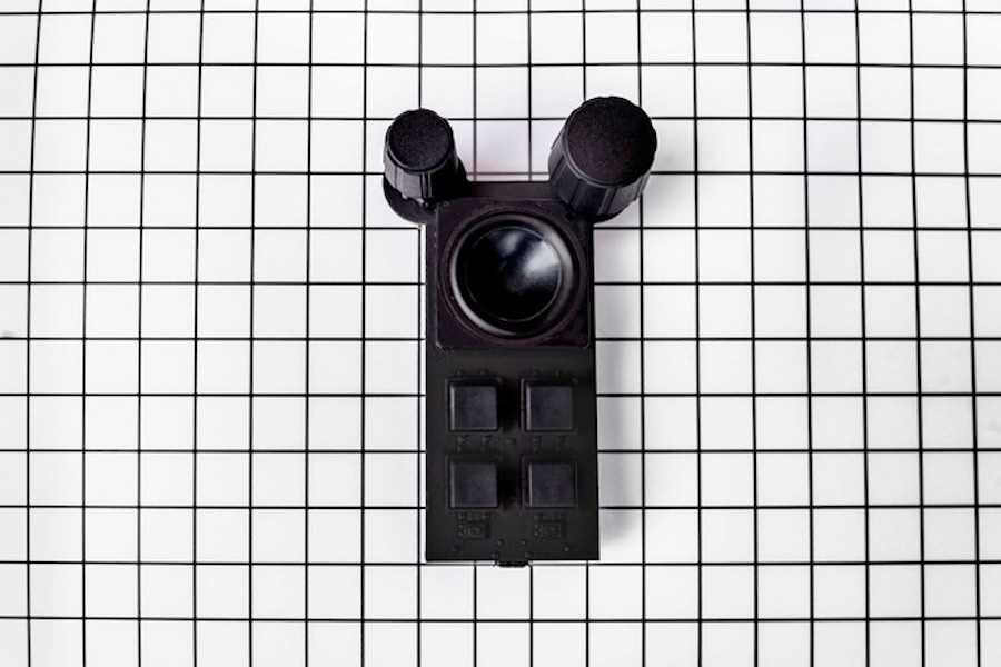
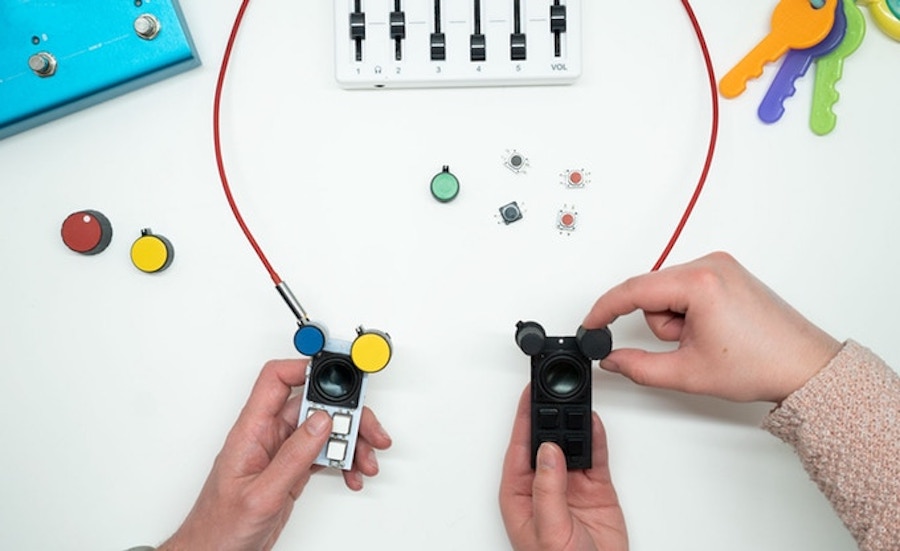
There are a wide variety of ways to create electronic music. For a capable machine that fits in the palm of your hand and is loud enough to use outdoors, however, it’s hard to imagine a battery-powered device cooler than Bitty from Curious Sound Objects.
The pocket-sized drum machine and synthesizer, currently on Kickstarter, was prototyped using an Arduino Nano and will be fully Arduino-compatible when released. This means that in addition to changing the sound and interface around with readily-available sound packs—which include Theremin Bitty, Techno Bitty, Basement Bitty, Trap Bitty, Lofi Bitty, and Beach Bitty—it can be programmed with the Arduino IDE. The device can even run sound software written for other Arduino boards.
Bitty features four sample trigger buttons, a pair of knobs, and a speaker. Designed for entry-level EDM enthusiasts and studio musicians alike, you can play the drums and melodies manually, as well as trigger patterns to produce dance music or hip hop beats. These can be chosen via the left knob, while the right knob handles pitch, note selection, and arpeggiation.
Check it out in action below!
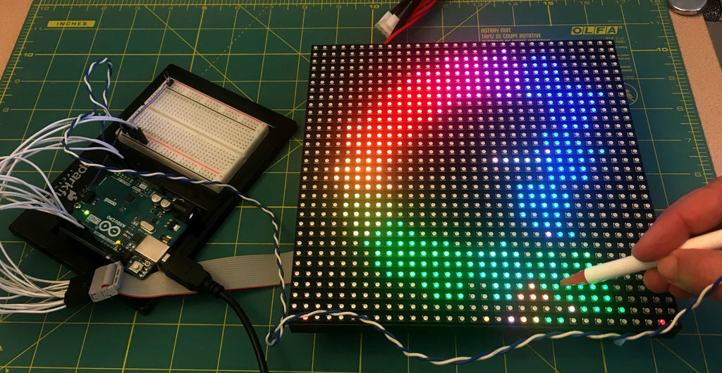
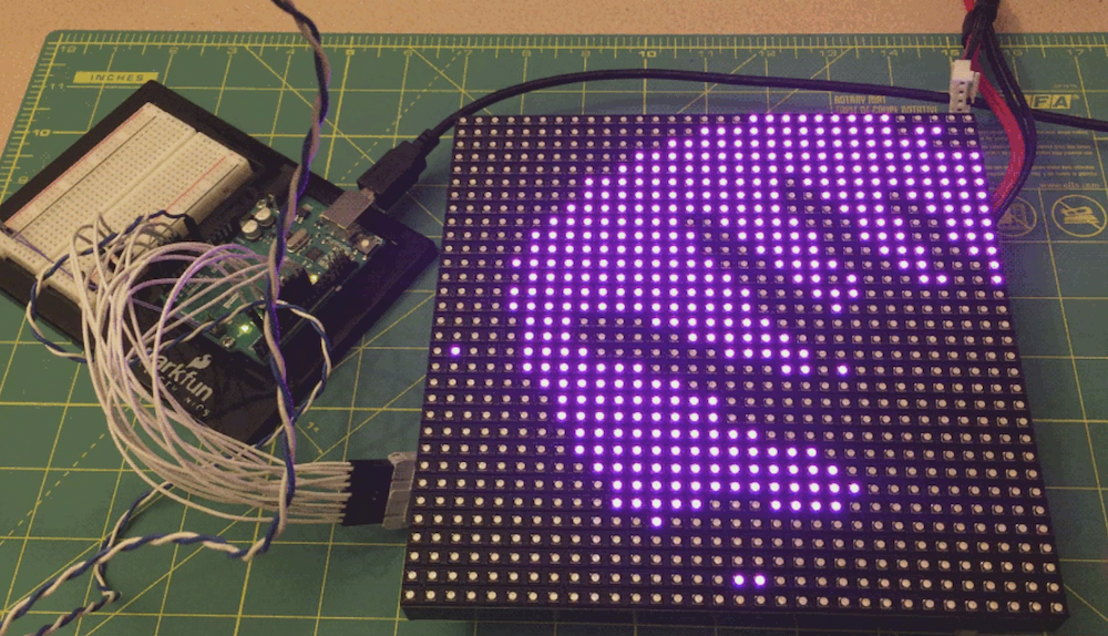
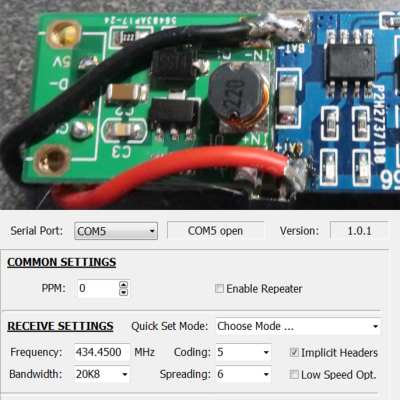 [Dave Akerman]’s interest in high-altitude projects means he is no stranger to long-range wireless communications, for which LoRa is amazingly useful. LoRa is a method of transmitting at relatively low data rates with low power over long distances.