Rudimentary ultrasound machine made with Arduino Due
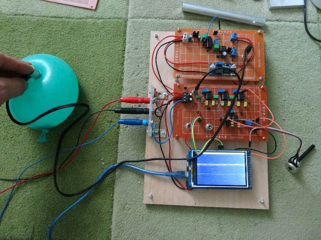
Ultrasound images are an important tool for medical diagnosis, and while units used by doctors can be very expensive, getting a basic image doesn’t have to be. Inspired by this attempt at a $500 ultrasound machine seen here, maker “stoppi71” decided to create his own using a 5 MHz ultrasound transducer via a paint-thickness gauge.
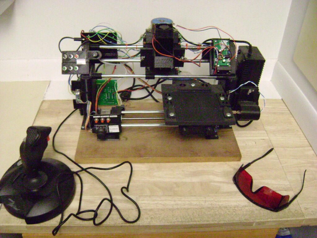
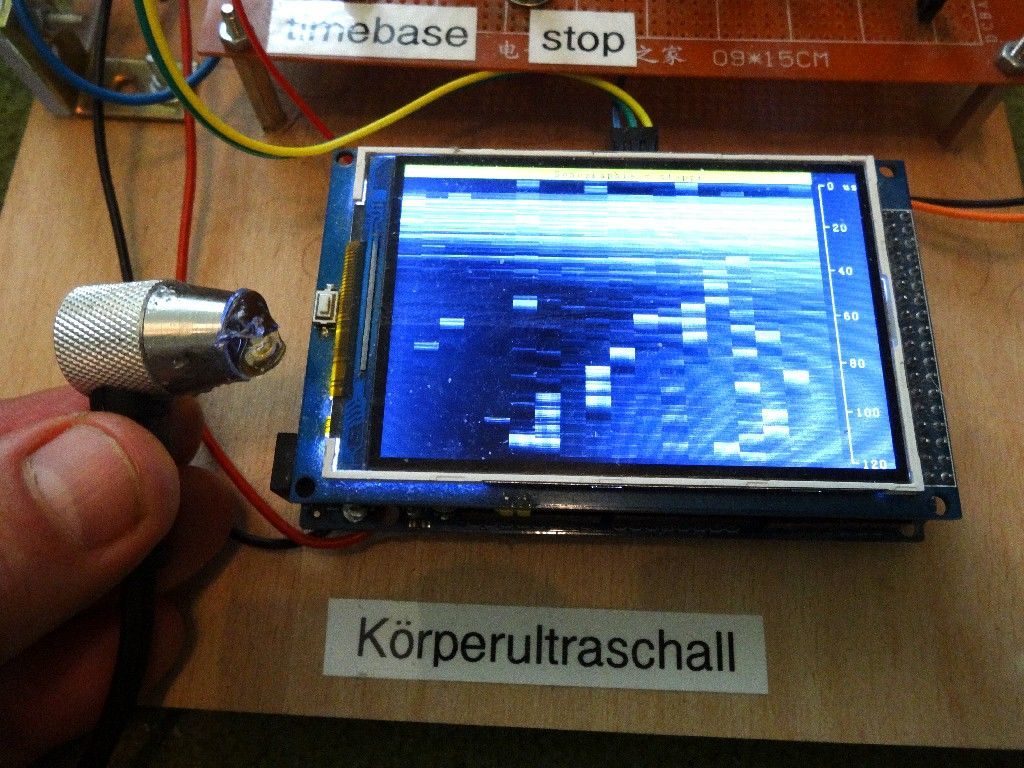
An Arduino Due provides computing power to turn sound pulses into images, while a 3.5-inch TFT display shows what it’s examining. Short pulses in the 100-200 nanosecond range are generated with the help of a monoflop and MOSFET, returning an echo corresponding to what it’s “looking” at.
Although the results are not nearly what you’d expect at the doctor’s office, rudimentary readings of skin and bone are definitely visible.
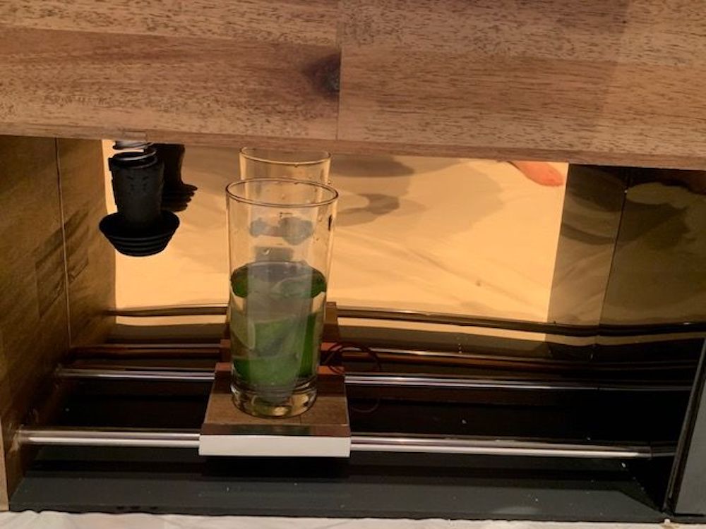
I’ve examined different objects from aluminum-cylinders over water-filled balloons to my body. To see body-echos the amplification of the signals must be very high. For the aluminum-cylinders a lower amplification is needed. When you look at the pictures you can clearly see the echoes from the skin and my bone.
So what can I say about the success or failure of this project. It is possible to look inside the body with such simple methods and using parts, which aren’t commonly intended for that purpose. But these factors are limiting the results too. You don’t get such clear and well structured pictures compared with commercial solutions.