Posts with «arduino» label

Build your child a wooden MP3 player for $100

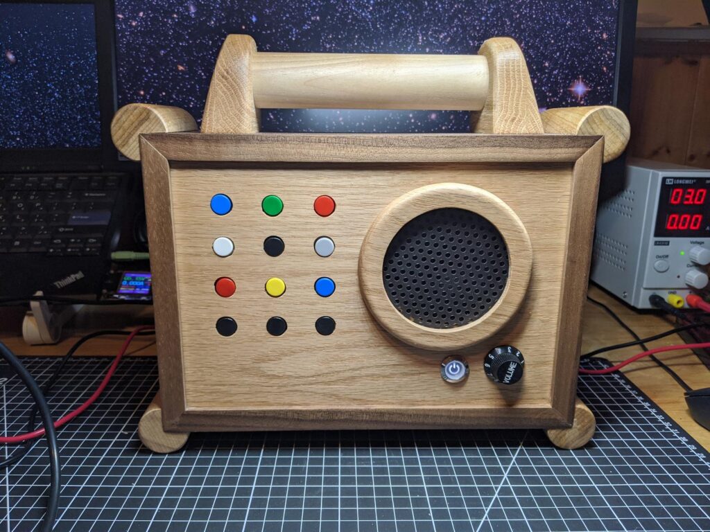
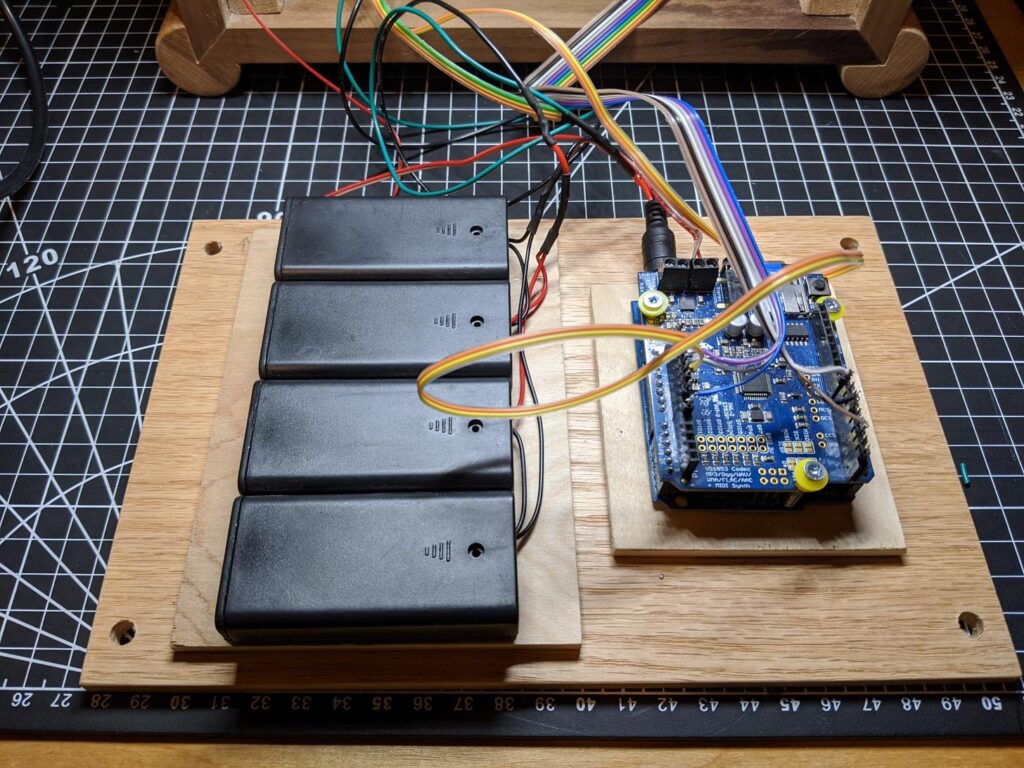
If your young child wants to listen to music, what better way than a beautiful wooden MP3 “radio,” with an array of buttons that select the album? After being inspired by a similar commercial product, Redditor “DerThes” decided to make such a device for a fraction of the cost using an Arduino Uno for control, along with a Music Maker Shield to play tunes off an SD card.

The toddler can select songs from a grid of 16 input buttons, which are sent to the Uno via a pair of shift registers. There’s also a “parent’s mode” with the ability to choose from up to 99 albums, and a volume knob for… adjusting the volume. 

Finally, the unt features a beautiful enclosure made out of oak and black walnut, with corners softened by dowels to reduce collateral damage “after the player has gone airborne.” More details can be seen on Imgur here and on GitHub.

This is an easy to use MP3 player for small children. I made this for my 2 year old for Christmas. Each of the top 9 buttons will play an album. The black buttons on the bottom are prev – play/pause – next. The player also supports an alternative playback mode that can be activated using a special key combination. That combination will turn the buttons into a 10 digit input matrix allowing playback of up to 99 albums. That way the player can be used by parents as well.

See GitHub for more details, the schematics for the button PCB and the firmware. https://github.com/MichaelThessel/arduino-stoerbert

This is heavily inspired by Hoerbert: https://en.hoerbert.com

When I first saw the Hoerbert at a friends place I wanted it for my child. After I heard of the $400 price tag I knew that I needed to spend 50 hrs and $100 to build my own.

Arduino Blog 30 Dec 16:49

Create your own Arduino Library

Project Description

In this short tutorial I will show you how to create your own Arduino Library. Making your own library seems daunting at first, but I will show you that it is not much harder than writing your own script/sketch. I would advise that you comment you code clearly, because when you come back to it in 5 years time, it will help to navigate you through your code at this time in history. Here we go, let's go through the process of creating a very simple Arduino library.

Parts Required

  • Arduino UNO or compatible board

Project Steps

Before we begin, there are a few questions you must ask yourself:

  1. What will the library be called ?
  2. What will the library do ?
  3. What are you trying to simplify?

For our library, these are the answers to the questions above:

  1. BlinkMe
  2. It will blink an LED attached to one of the digital pins
  3. The aim is to reduce the blink commands to a single line

Create a Folder

Create a folder on your computer which will be used to house all of the files in this project. Name the folder the same name as the library. In this case we will name it "BlinkMe". Make sure you use consistent naming throughout the tutorial. Capital and lowercase letters do matter.

Create the files

Using any text based editor (eg. notepad++, PSPad, Notepad2 etc), you will need to create 3 blank files:

  • The C++ file (BlinkMe.cpp) : Library code containing all of the functions
  • The Header file (BlinkMe.h): Contains the library function declarations
  • keywords.txt : Used for syntax highlighting within the Arduino IDE

I will tell you what you need to write inside each of these files, but make sure you have the blank BlinkMe.cpp, BlinkMe.h and keywords.txt files inside of the BlinkMe folder. Some people start by creating the header file first, but I personally like to start with the CPP file.
We will now look to populate the BlinkMe C++ file:

The C++ file (.cpp)

This file will contain all of the functions in your new library.
The first thing you will need to do is include the Arduino.h file. This will drag in all of the relevant Arduino code necessary for your library to function with an Arduino. And while we haven't yet created the header file (BlinkMe.h), we need to import that also. So the first two lines should be:

#include <Arduino.h>
 #include <BlinkMe.h>

The next section of code is the "constructor". This will be responsible for constructing the BlinkMe object. The BlinkMe object will allow you to call any of the public functions within the BlinkMe library. The constructor will allow us to define the default variables or constants.

BlinkMe::BlinkMe(){
    _dPin = 13;
 }

Sometimes we will want to blink an LED on a different pin. So we will create a function to set the pin that we would like use.

void setOUTPUT(int dPin){
    _dPin = dPin;
    pinMode(_dPin, OUTPUT);
 }

The only thing left is to create the useful part of the code. We will create a simple function that will blink the LED for a set duration. The function will have a parameter, which will be used to set the blink duration.

void blink(unsigned long delay_1){
    _delay_1 = delay_1;
    digitalWrite(_dPin, HIGH);
    delay(_delay_1);
    digitalWrite(_dPin, LOW);
    delay(_delay_1);
 }

Here is the complete "BlinkMe.cpp" file:

The Header file (.h)

The header file will be used to create the library function declarations. Open the "BlinkMe.h" file.
The first step is to check to make sure that the library is NOT already defined:

#ifndef BlinkMe_h

If it is not defined, then we must define the library:

#define BlinkMe_h

We then need to provide access to the standard Arduino types and constants

#include "Arduino.h"

And finally create the BlinkMe class:

//Create the class BlinkMe
class BlinkMe{
    public:
        BlinkMe();
        void setOUTPUT(int dPin);
        void blink(unsigned long delay_1);
    private:
        int _dPin;
        unsigned long _delay_1;
 };
#endif

Here is the complete header file:

keywords.txt (optional)

The keywords.txt file will contain the keywords for the library which will allow appropriate syntax highlighting. This file is optional, however it will highlight your classes or functions based on the keyword mapping.

  • LITERAL1: specifies constants (eg. HIGH, LOW,
  • KEYWORD1: specifies classes (eg. Serial)
  • KEYWORD2: specifies methods and functions (eg. analogRead, digitalWrite, delay)
  • KEYWORD3: specifies structures (eg. if, while, loop)
You need to make sure you use a single tab between the keyword and the "KEYWORD" mapping. In our example, BlinkMe is a class, so that would be a KEYWORD1. On the other hand, "blink" is a function, so that would be a KEYWORD2. So the keywords.txt file will contain the following text:

BlinkMe     KEYWORD1
setOUTPUT   KEYWORD2
blink       KEYWORD2

Example Sketch (optional)

It is often useful to include an sketch that provides an example of the library in use. It provides some context. If you plan to include the sketch in your library, then you must follow these simple rules:

  1. Create an "examples" folder.
  2. Create an example sketch, an place it within a folder of the same name as the sketch
  3. Place the sketch folder inside of the examples folder
You will end up with something like: examples/example_sketch/example_sketch.ino
In our case it will be: examples/blinkTest/blinkTest.ino

Here is the example sketch for this library (Save as blinkTest.ino):


The library

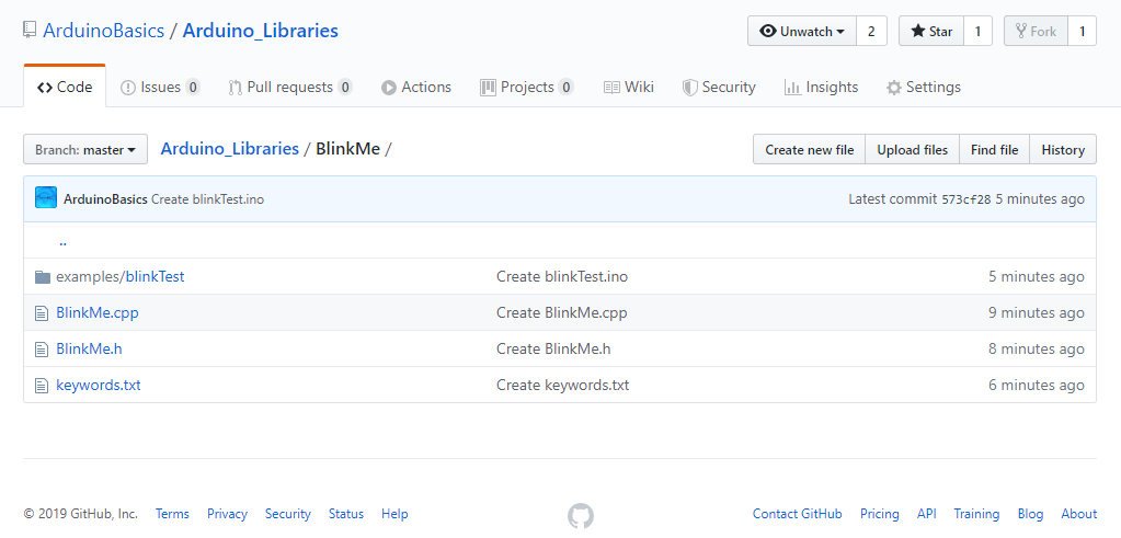
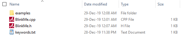
Here is a picture of the library contents:

And now the only thing left is to zip up the library folder and import it into the Arduino IDE. Use whatever program you want to zip up the BlinkMe folder, and note the location of the zip file. You need to import the zip file into the Arduino IDE:

  • Arduino IDE > Sketch > Include Library > Add .ZIP Library...
  • Select the library zip file you just created, and select "Open".
  • You can now use your library in the Arduino IDE.
  • Test it by running your example sketch: File > Examples > BlinkMe > blinkTest

Download

You can download the entire library here:
BlinkMe Library

Conclusion

In this tutorial, I showed you how to create a simple Arduino library. If you would like so see another example, have a look at my ToggleTimer library, which is very useful when trying to blink an LED without using a delay.You don't have to limit yourself to LEDs, you can use it for other projects where delay gets in the way. ToggleTimer is a non-blocking timer that toggles between two states.


If you found this tutorial helpful, please consider supporting me by buying me a virtual coffee/beer.

$3.00 AUD only

Social Media

You can find me on various social networks:

Follow me on Twitter: ScottC @ArduinoBasics.
I can also be found on Instagram, Pinterest, and YouTube.
And if all else fails, I have a server on Discord.


ScottC 29 Dec 10:09
arduino  blink  diy  led  library  tutorial  

Need Hackable Melodies? Here’s The TETRIS Theme and More

[Robson Couto] started to get interested in musical projects and as a side effect created downloadable code with simple notation for a good variety of themes, songs, and melodies. They are all for the Arduino and use only the built-in tone() function, but don’t let that distract you. If you look past that, you’ll see that each sketch is a melody that consists of single notes and durations; easily adapted to other purposes or simply used as-is. After all, [Robson] wanted the source of each tune to be easily understood, easily modified, and to have no external dependencies.

All that may sound a bit like MIDI, but MIDI has much more in common with hardware events than music notation because it includes (among other things) note starts and note ends as separate elements. Converting MIDI into a more usable format was a big part of a project that fed Bach music to a neural network and got surprisingly good results.

When doing music projects, sometimes having a recognizable melody represented very simply as notes and durations with only one note at a time can be an awfully handy resource, and you can find them on GitHub. There’s a brief video of the Tetris theme (actual name: Korobeiniki) being played after the break.

Hack a Day 25 Dec 18:00

Arduino Polygraph Shows How It’s Done

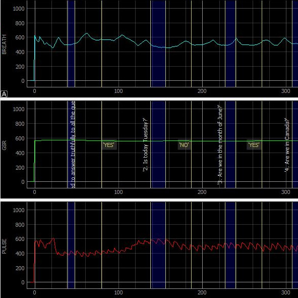
Sometimes, a project comes along that makes a good reference design for anyone doing similar work. In this particular case, it’s a DIY USB polygraph-like machine by [Juangg] using an Arduino and sensors on the hardware side, and a Python front end for data visualization. It’s even complete with 3D printed enclosure and sensor elements.

[Juangg] designed it to use three sensors: a pulse sensor, a breath sensor, and one to measure Galvanic Skin Response (GSR). The pulse sensor uses a piezo element pressed against a fingertip to detect changes in pressure resulting from blood flow. It can be picky about placement, but finding sweet spot can yield remarkably good readings. The breath sensor works on a similar principle but uses a 3D printed fixture to hold the sensor between a strap and the subject’s chest, so that breathing in and out can be detected. The GSR sensor is a voltage divider used to measure small changes in skin conductivity. How well does it all work? That depends on what one is looking to get out of it, but the documentation and design files are available from the project page and the GitHub repository if anyone wants a reference for similar work.

The polygraph may have a mixed reputation, but it makes a good project that demonstrates just how messy biometrics can be from an engineering perspective. And in case you missed it, here’s a reminder that Wonder Woman and the polygraph have much more in common than you might realize.

Minimalist Mate Maker Keeps You Caffeinated

Americans love their coffee. The Brits adore their tea. In South America, the number one way to get through the day is with yerba mate, a tea made from the yerba plant. It is typically shared in a social setting, with one person preparing the beverage for everyone to enjoy. Although caffeine certainly deserves a ceremony, it never needs one. Hit the streets and you’ll see people everywhere with a thermos under one arm, keeping water hot and ready to refill the cup of mate in their hand.

The Stanley vacuum thermos is quite a popular choice for drinkers on the go, but the Argentinian government recently placed new restrictions foreign imports. [Roni Bandini] decided to build a minimum viable mate machine so he always has perfectly hot water on tap.

An Arduino Nano heats the water and displays the rising temperature on an LCD screen. When the temperature is just right, the display asks for your cup. An ultrasonic sensor detects the cup and dispenses a certain amount of water determined in the sketch. Yerba leaves can be used a few times before losing their flavor, so the machine keeps track and lets him know when it’s time to replace them. You can sip on a brief demo after the break.

Let’s say you don’t have perfectly-prepared mate, and it always comes out too hot. That’s better than too cold, but still not ideal. Why not make a temperature-sensing coaster that alerts you when it has cooled to perfection?

Full control of your TV using Alexa and Arduino IoT Cloud

We’re excited to announce that the official Arduino Amazon Alexa skill now supports television control.

You can now securely connect your TV set to Alexa using Arduino IoT Cloud and a few lines of code.

Here are some of the features which will be available to you:

  • Power on/off
  • Switch channel
  • Volume up/down/mute
  • Switch input sources

The easiest way to operate any kind of television is to act as if we were its very own clicker. In order to do so, we’ll show you how to capture the commands from the remote and play them back via Arduino (the TV will never know what hit it).

We’ll then create an Arduino IoT Cloud Thing with a TV property, and adapt the generated code to our needs. Finally, we’ll configure Alexa to access and control our TV.

Afterwards, we’ll be able to ask things such as:

  • “Alexa, turn the volume up on TV.”
  • “Alexa, mute TV” or “Alexa, unmute TV.”
  • “Alexa, next channel on TV.”

The complete step-by-step guide is available on our Project Hub.

Share your creativity with us! Our community means a lot to us, so we would love to see what you create. Make sure you document and post your amazing projects on the Arduino Project Hub and use the #ArduinoAlexa hashtag to make it discoverable by everyone!

Have fun playing with Alexa and IoT Cloud. If you have questions and/or build this project, let us know in the comments below.

Make’s Guide to Boards Has a Hidden Secret!

Want to see something super cool? Go grab your copy of Make: Vol. 68 and download the Digi-Key AR Guide to Boards app, then put them together to watch real magic happen. 

Read more on MAKE

The post Make’s Guide to Boards Has a Hidden Secret! appeared first on Make: DIY Projects and Ideas for Makers.

Optical Communication Using LEDs Alone

We’re all used to the humble LED as a ubiquitous source of light, but how many of us are aware that these components can also be used as photodiodes? It’s something [Giovanni Blu Mitolo] takes us through as he demonstrates a simple data link using just a pair of LEDs and a couple of Arduinos. It’s a showing off his PJON networking layer, and while you’d need a bit more than a couple of LEDs on breadboards for a real-world application, we still think it’s a neat demonstration.

PJON itself is very much worth a look, being an implementation of a robust and error-tolerant network for Arduinos and other small microcontroller platforms. It has a variety of communication strategies for various different media, and as this LED demonstration shows, its strength is that it’s capable of working through media that other networks would balk at. Whether it’s controlling home automation through metal heating ducts or providing an alternative to LoRa at 433 MHz, it’s definitely worth a second look. We’ve mentioned it before, but remain surprised that we haven’t seen it more often since. Take a look, the video is below the break.

Hack a Day 22 Dec 09:00

HeyTeddy is a conversation-based prototyping tool for Arduino

Programming an Arduino to do simple things like turn on an LED or read a sensor is easy enough via the official IDE. However, think back to your first experiences with this type of hardware. While rewarding, getting everything set up correctly was certainly more of a challenge, requiring research that you now likely take for granted.

To assist with these first steps of a beginner’s hardware journey, researchers at KAIST in South Korea have come up with HeyTeddy, a “conversational test-driven development [tool] for physical computing.” 

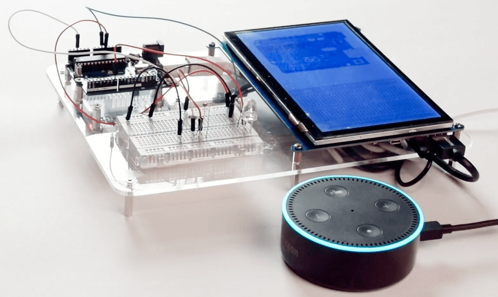
As seen in the video below, HeyTeddy’s voice input is handled by an Amazon Echo Dot, which passes these commands through the cloud to a Raspberry Pi. The system then interacts with the physical hardware on a breadboard using an Arduino Uno running Firmata firmware, along with a 7” 1024 x 600 LCD touchscreen for the GUI. Once programmed, code can be exported and used on the board by itself.

Those wishing to learn more can check out the entire research paper here

HeyTeddy is a conversational agent that allows users to program and execute code in real-time on an Arduino device without writing actual code but instead operating it through dialogue. This conversation can either be based on voice or text (through a Web chat). Commands spoken to HeyTeddy are parsed, interpreted, and executed in real-time, resulting in physical changes to the hardware. For example, the “write high” command configures an I/O pin to behave as a digital output with its internal state set to high (e.g., a 5V logic level), making driving an LED possible. Hence, the user does not need to write any code, compile it, deal with errors, and manually upload it on the hardware.

Furthermore, HeyTeddy supervises the user’s choices, preventing incorrect logic (e.g., writing an analog value to a digital pin), guiding the user through each step needed to assemble the circuit, and providing an opportunity to test individual components through separate unit tests without interrupting the workflow (i.e., TDD functionalities). Finally, the user has the option of exporting the issued commands as a written code for Arduino (i.e., an Arduino sketch in C++, ready for upload). 

Programming Arduinos With Voice Commands

Programming is a valuable skill, though one that can be daunting to learn. Throw hardware in the mix, and things ratchet up another level again. However, there are many projects that have sought to reduce the level of difficulty for newcomers. HeyTeddy is a new project that allows users to program an Arduino with voice commands, and the help of on-screen tutorials.

It’s a system that initially sounds cumbersome, but through smart design, is actually quite streamlined. Users can talk to the system, which uses an Amazon Alexa device for natural language voice recognition. This enables HeyTeddy to respond to questions like “how do I use a flex sensor?” as well as direct commands, such as “Set pin 10 to 250”.

The demo video does a great job of demonstrating the system. While the system is not suited to professional development tasks, its has value as an educational tool for beginners. The system is able to guide users through both hardware setup on a breadboard, as well as guide them through tests when things don’t work. Once their experience level builds, code can be exported to the Arduino IDE for direct editing.

It’s a great tool that has plenty of promise to bring many more users into the hardware hacking fold. It’s out of the workshop of [MAKInteract], whose work we’ve seen before. Video after the break.

Hack a Day 20 Dec 09:00