Posts with «arduino» label

Low cost Ethernet shield with ENC28J60

Economical alternative to original Arduino ethernet shields, allows data rates up to 10 Mbps and is achieved with a traditional assembly components.

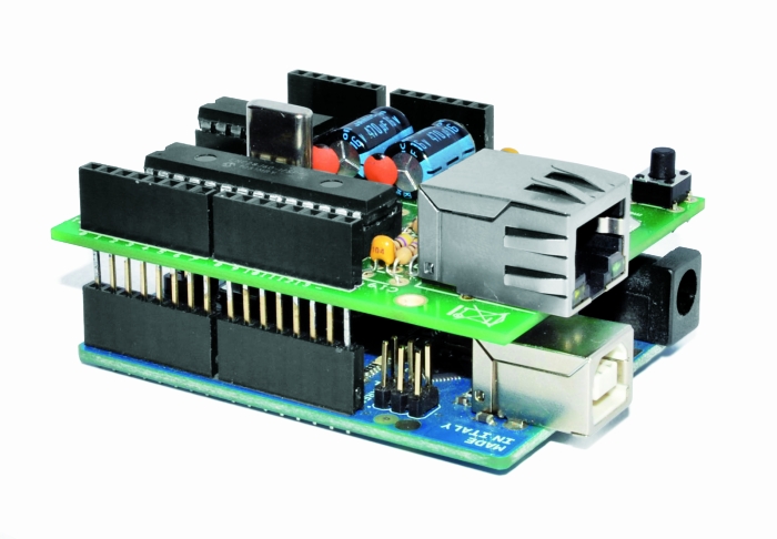
One of the most interesting shield that you can mount on the Arduino platform is certainly the ethernet shield, because enable numerous networking applications such as remote control of systems and users, web access and publication of data, and more yet, the simplicity of finding and integrating open-source libraries on Arduino IDE does the rest. The usefulness of LAN connectivity has meant that the market would respond by offering different ethernet shield, first of all the original Arduino Ethernet Shield, which was accompanied by the good shield by Seeed Studio, both of these circuits are based on the chipset WIZnet W5100, allow multiple socket connections and can work at 100 Mbps

This ethernet shield is low-cost thanks to components used: all traditional mounting (THT). This feature makes the circuit accessible to those who haven’t the equipment to assemble SMD components. The data-rate is limited to 10 Mbps.
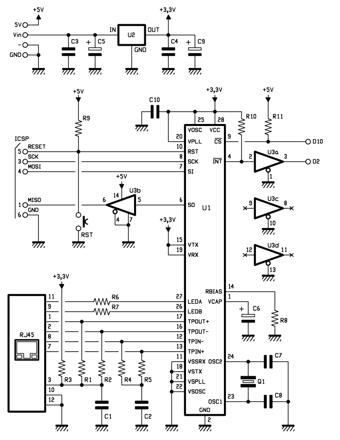
 

Wiring diagram

The shield is based on a Microchip ENC28J60 chip that interfaces with Arduino and data conversion according to the ethernet protocol. It integrates the MAC controller, an 8 KB Transmit / Receive Packet Dual Port Buffer and a circular FIFO managed at the hardware level, allows the programming of data retransmission in case of collision.
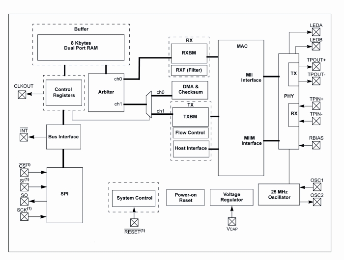
The MAC controller supports both Unicast, Multicast and Broadcast packets, has a programmable 64-byte pattern within a margin allowed to the user and programmable wake-up on multiple packet formats (Magic Packet, Unicast, Multicast, Broadcast, specific packet match or any packet).


In the circuit we see that over all’ENC28J60 there are a standard RJ45 jack with integrated LEDs, filters and line transformers, and a voltage level shifter for the SPI interface to communicate with the Arduino.

MISO is the output data of the slave device and the input of Arduino, while MOSI is the opposite; SCK is the clock that marks the two-way communication on the SPI bus and RESET the reset line, which is also connected to a button that allows you to reset the Ethernet interface, if necessary, manually. The digital D10 and D2 lines of Arduino are used, respectively, for the control of CS (Chip Select, active logic zero) and the reading of INT. U3B is used to adapt the logic levels 0/3, 3 V to those of Arduino 0/5 V.

The ENC28J60 operates with a clock of 25 MHz, defined by the quartz Q1 connected between the pins 23 and 24; the capacitor connected to pin VCAP filters the output voltage (2.5 V) of the internal controller and should preferably be of the type low ESR (low series resistance parasite). The resistor connected to RBIAS is used to bias the LAN transceiver that is part of the pin TPIN + / – and TPOUT + / -.

We conclude the analysis of the circuit diagram of the shield with the power that is drawn by Arduino 5V and Vin through the strip: the first provides the 5 volts continuous stabilized points of the circuit that require them (basically the 74HC125 and the resistance of pull Line-up reset and Chip Select) and the second give power to the integrated regulator U2, which creates the 3.3 volts needed to power the microcontroller and circuits contained in the RJ45 jack.


The library for ENC28J60


The original library from which we derived can be downloaded from the site https://github.com/jcw/ethercard ; from our site you can download the library itself but with a higher number of application examples.

Here you will find a sketch example to build a Web Server, in particular, in the current web page you will see the hours: minutes: seconds elapsed from the ignition of Arduino.


// This is a demo of the RBBB running as webserver 
// with the Ether Card
// 2010-05-28 
// http://opensource.org/licenses/mit-license.php

#include

// ethernet interface mac address
static byte mymac[] = { 0x74,0x69,0x69,0x2D,0x30,0x31 };
// ethernet interface ip address
static byte myip[] = { 192,168,0,188 };
// gateway ip address
static byte gwip[] = { 192,168,0,1 };

byte Ethernet::buffer[500];
BufferFiller bfill;

void setup () {
  if (ether.begin(sizeof Ethernet::buffer, mymac) == 0)
    Serial.println( "Failed to access Ethernet controller");
  ether.staticSetup(myip);
}

static word homePage() {
  long t = millis() / 1000;
  word h = t / 3600;
  byte m = (t / 60) % 60;
  byte s = t % 60;
  bfill = ether.tcpOffset();
  bfill.emit_p(PSTR(
    "HTTP/1.0 200 OK\r\n"
    "Content-Type: text/html\r\n"
    "Pragma: no-cache\r\n"
    "\r\n"
    "<meta http-equiv='refresh' content='1'/>"
    "<title>RBBB server</title>" 
    "<h1>$D$D:$D$D:$D$D</h1>"),
      h/10, h%10, m/10, m%10, s/10, s%10);
  return bfill.position();
}

void loop () {
  word len = ether.packetReceive();
  word pos = ether.packetLoop(len);

  if (pos)  // check if valid tcp data is received
    ether.httpServerReply(homePage()); // send web page data
}


Library Ethernet shild with ENC28J60 

Store

Arduino Current Output

Hi there,

I have an LCD03 which i'm controlling via serial. See here: http://www.technobotsonline.com/lcd03-i2c--serial-display-32400.html

read more

Robot dares you to snatch the pebble from this flower

This pleasant-looking plant may try to take your hand off if you’re not careful. The robot flower (translated) includes sensors that cause the petals to move in reaction to external stimuli.

You can just make out the distance sensors as black rectangles on two of the petals. These let the flower track an object by rotating the flower stem. But if they determine the object is getting a bit too close for comfort, the servo motor on the back of each petal will cause the flower to suddenly clamp shut.

The video after the break starts off with an in-depth look at the hardware that went into the project. An Arduino clone called the GRoboduino makes this project a lot easier since it has a bunch of extras on the board aimed at things like sensors and servo motors. The mounting technique for the petal-powering-servos is quite attractive, and we enjoy the Snapple lid (probably not the actual brand but you get the picture) which has been coated with yellow felt for the center of the bloom. The final look is normal enough to fit in with home decor, but it still has enough geek in it to melt our hacker hearts.

[via Make]


Filed under: robots hacks
Hack a Day 30 Jun 00:01

Electric bike (earplugs not included)

It’s obvious this bike has some extra parts. But look closely and you’ll see the chainring has no chain connecting to it. Pedaling will get you nowhere since [PJ Allen] rerouted the chain in order to drive this bicycle using an electric motor.

He’s got beefy motor which pulls 350 Watts at 24 Volts. For speed control he opted to use an Arduino, pumping out PWM signals to some MOSFETs. This results in an incredibly noisy setup, as you can hear in the bench test video after the break. But once this is installed on the bike it doesn’t quiet down at all. You can hear the thing a block away.

The original road test fried the first set of 7A MOSFETs when trying to start the motor from a standstill. It sounds like the 40A replacements he chose did the trick through. We didn’t see any information on the battery life, but if he runs out of juice on the other side of town we bet he’ll be wishing he had left the chain connected to the crankset.


Filed under: transportation hacks
Hack a Day 29 Jun 22:01

Slouch Detecting Belt

Ellen Sundh’s Bad Posture belt uses an Arduino, wave shield, and a flex sensor to detect when the user slouches. If your posture needs correcting, the belt literally yells at you. How’s that for motivation?

The belt is calibrated when the user presses a pushbutton after attaining good posture. After that, he/she is free to be lambasted by this piece of wearable tech.

[via The Creators Project]


Fighting over the Frat’s TV remote

[Colin Bookman] lives in a Fraternity house and apparently the remote for the cable box has a way of walking off. He figured out a method to give everyone control of the TV channel in one form or another.

The cable box can be seen perched on that shelf, and [Colin's] addition is the wooden box sitting on the floor. Inside is an Arduino board, and the cable snaking out of the enclosure is an IR LED. This give the Arduino the ability to send remote control commands to the TV box. The two arcade buttons on the front will switch the channel up or down.

But this is hardly a remote control replacement since you have to get up to use it, so he went a few steps further. The Arduino board was paired with an Ethernet shield. It serves up a web page that has a virtual keypad. So anyone with a smart phone or laptop can log into the server and start changing the channels. We’re not sure if this provides relief from a missing remote, or promotes impromptu fist fights when brothers can’t agree on what to watch. It certainly opens up the possibility of long-distance trolling as you could be sitting in class and decide to change the channel to Lifetime every ten minutes or so.

If you don’t have an Ethernet shield handy we’ve seen a similar setup that uses Bluetooth instead the network.


Filed under: home entertainment hacks

Using the MakerShield – LCD Display

An LCD screen can bring a whole new level of interactivity to your Arduino projects. They can provide instant data without using your computer and give visual feedback about your project. Normally, you would use a separate breadboard to hook up an LCD but using a MakerShield and this tutorial from Make: Projects, you can make your own LCD shield!

LCD screens look complicated but using an Arduino it’s not too bad at all. This tutorial will teach you how to hook up an LCD display to an Arduino using a MakerShield. All the components you need for this build are included in the Ultimate Microcontroller Pack.

You can pick up an Ultimate Microcontoller Pack from the Maker Shed, Micro Center, and select RadioShack locations. Call me crazy but I love the look of all those jumper wires!

More:
Using the MakerShield – Button
Using the MakerShield – Servo Control


Turning an Arduino into a USB keyboard

The newly released Arduino Leonardo has a few very interesting features, most notably the ability to act as a USB keyboard and mouse thanks to the new ATmega 32U4 microcontroller. This feature isn’t exclusive to the Leonoardo, as [Michael] explains in a build he sent in – the lowly Arduino Uno can also serve as a USB HID keyboard with just a firmware update.

The Arduino Uno (and Mega) communicate to your computer through a separate ATmega8U2 microcontroller. Simply by uploading new firmware with the Arduino Device Firmware Upgrade, it’s easy to have your old Arduino board gain some of the features of newer boards such as the Teensy or Leonardo.

[Michael] goes through the steps required to make this upgrade work and ends his build by showing off an Arduinofied ‘cut, copy and paste’ button project as well as a few multimedia controls. You can check those builds out in the video after the break.

If emulating a USB keyboard isn’t your thing, it’s also possible to install LUFA firmware to emulate everything from joysticks to USB audio devices. Very cool, and very useful.


Filed under: arduino hacks, peripherals hacks
Hack a Day 29 Jun 12:01

**********Stereo Audio VU meter on Arduino**********

This blog is a sequel of “Tears of Rainbow”.  Using the same hardware set-up of Gigantic RGB LED display, I decided to re-work software a little bit, in order to display the true RMS amplitude of musical content. Video clip on youtube:                       VU_Meter   640×480                                      VU_Meter_HD

Objective:

  • Stereo input, process both channel;
  • Full audio band, 40 Hz – 20 kHz;
  • Fast update rate of visual output.
  • Precision Full-Wave  measurements. 

To process stereo input, this time arduino is switching ADC multiplexer every time when it finish sampling input data array (size=128). Two channels “interleaved” with frame rate 78 Hz, so during each frame only one channel sampled / processed, and update rate per channel is equals to 78 / 2 = 39 Hz, which is more than enough for most audio applications.

 I’m using FFT Radix-4  to extract RMS magnitude of audio waveform, and this is why:

1.  Sampling rate in this application is 10 kHz. How I achieved  20 kHz stated in objective section, doing sampling only 10 ksps?  >>>Aliasing!<<<   What is considered to be nightmare when we need spectral information from FFT output, aliasing in this project is really helpful, reflecting all spectral components around  axis – 10 kHz back “to the field”. As all bins going to be sum-up there is no issue, only benefits. Due aliasing, I’m able to use low sampling rate, and reduce CPU workload down to 52%.

2.  In order to get accurate magnitude calculation of RMS,  which is defined as square root of the sum of squares divided by number of samples per specified period of time:    V(rms) = √ ( ∑ Vi ^2 ) / N) DC offset  must be subtracted from the input raw data of each sample    Vi = Vac + Vdc   (if you remember, AtMega328 ADC needs DC offset to read AC negative half-wave).  The problem here, DC offset value is never known with high accuracy due bunch of reason, like voltage stability of PSU,  thermal effects, resistors tolerance (+/- 1 or 5 %), ADC internal non-linearity etc. Cure for this, which works quite well for monitoring electrical grid power, high pass filter (HPF). Only instead of single 50/60 Hz frequency of power line,  I have a wide frequency range, starting from 20 Hz and ending at 20 kHz. When I feed specification of the HPF:

  • Sample Rate (Hz) ? [0 to 20000]                     ? 10000
  • Desired stop-band attenuation (dB) [10 to 200] ? 40
  • Stop-band edge frequency Fa [0 to 5000]         ? 0
  • Pass-band edge frequency Fp [0 to 5000]        ? 40

to  Parks-McClellan FIR filter design algorithm (one of the most popular, and probably, the best) it provides the result:

  • …filter length: 551 …beta: 3.395321

551 coefficient to be multiplied and sum up (MAC-ed) every 100 usec! No way. I’m not sure, if it could be done on 32-bits 100 MHz platform with build-in MAC hardware, but there is no way for 8-bit 16 MHz Arduino.

IIR filter wouldn’t make much difference here. It has lower quantity of multiplications, but more sensitive for truncation and rounding error, so I’d have to use longer (32-bits?) variables, which is not desirable on 8-bit microprocessor at all.

And here comes FFT Radix-4, which easily fulfill this extra-tough requirements in the most efficient and elegant way. All I have to do, is just NOT include bin[0] in final sum, and all DONE!. TOP-FLAT  linear frequency response  40 Hz – 20 kHz  ( -3 dB ), with complete suppression of DC, and low frequency rumble below 20 Hz attenuation.  Linearity is better than +-1 dB between 80 – 9960 Hz.

Last things, audio front-end. As VU meter was designed in stereo version, I’ve build another “line-in”  pre-amplifier based on this kit: Super Ear Amplifier Kit

Link to Download a sketch:  Stereo_VU_Meter.


Modified Stereo VU meter, Logarithmic scale, 8 bars per channel, spacing 6 dB.

Dynamic range: 8 x 6 = 48 dB.  Stereo_VU_Meter(Log10).
 Next blog:   Extending dynamic range to 72 dB! 

Android ADK2012 is here and is powered by Arduino technology


ADK2012 board

Google has unveiled at Google IO their new  Accessory Development Kit for Android mobile phones and tablets, the ADK2012

The ADK2012 is based on the upcoming Arduino Due platform and the new Arduino IDE that supports programming ARM targets.

Currently the IDE works only on the Google ADK board released at Google IO, while the official launch of the Arduino Due is due later in the year.


Arduino Blog 28 Jun 20:35
adk  arduino