Daughter boards for microcontroller systems, whether they are shields, hats, feathers, capes, or whatever, are a convenient way to add sensors and controllers. Well, most of the time they are until challenges arise trying to stack multiple boards. Then you find the board you want to be mid-stack doesn’t have stackable headers, the top LCD board blocks the RF from a lower board, and extra headers are needed to provide clearance for the cabling to the servos, motors, and inputs. Then you find some boards try to use the pins for different purposes. Software gets into the act when support libraries want to use the same timer or other resources for different purposes. It can become a mess.
The alternative is to unstack the stack and use external boards. I took this approach in 2013 for a robotics competition. The computer on the robots was an ITX system which precluded using daughter boards, and USB ports were my interface of choice. I used a servo controller and two motor controllers from Pololu. They are still available and I’m using them on a rebuild, this time using the Raspberry Pi as the brain. USB isn’t the only option, though. A quick search found boards at Adafruit, Robotshop, and Sparkfun that use I2C.
This approach has challenges and benefits. A stack of daughter boards makes a neat package, where external boards makes a tangle of wires. Random sizes can make mounting a challenge. Providing power can also be a hassle because of the random placement of power pins. You can’t rely on USB power, especially from a Raspberry Pi whose USB is power limited.
On the other hand, external boards can offload processing from your main processor. Once a command is sent, these boards handle all the details including refresh requirements. They are likely to provide capabilities beyond the microcontroller software libraries since their processors are dedicated to the task.
I am using an 18-channel board from the Pololu Maestro Servo Controller family of boards that control from 6 to 24 servos using a single board. You might find the Adafruit 16 channel I2C board a useful alternative. For motor control I turned to the Pololu Simple Motor Controller family using one that will handle 18 amps. Others will handle from 7 to 25 amps. Or consider the Sparkfun Serial Controlled Motor Driver. Another source for USB controllers is Phidgets. I experimented with one of their spatial devices for the original robot. I should have used it to measure the tilt since one of my robots rolled over on a hill. Ooops!
Servo Control
The board currently installed on my robot is the Mini Maestro 18. The Maestro provides control over the servo speed, acceleration and movement limits. A home position can be set for startup or when errors occur. You can even do scripting or set movement sequences to play on command.
 On the hardware side, the Maestro also allows channels to be used for digital input or output, and some channels for analog input. On some there is one channel for pulse width modulation output. An onboard regulator converts the servo power input to the voltage needed by the processor, simplifying part of the power distribution challenge.
My previous robot used the Maestro to control pan and tilt servos for camera positioning, a servo to lift samples from the ground, and a safety LED. Two analog inputs from current sensors on the motors helped avoid burnout during stalls, and four inputs from a simple RF key fob transmitter provided control. The latter came in handy for testing. I’d program a test sequence such as starting a 360° camera scan for landmarks or drive onto the starting platform and drop the sample. A button press on the key fob would initiate the activity. One button was always set up as an emergency halt to stop a rampaging robot. The rebuild is following this pattern with some additions.
Motor Controller
The two Simple Motor Controllers (SMC) each handled the three motors on either side of the Wild Thumper chassis. The SMC does more than just control the motor speed and direction. You can set acceleration, braking, and whether forward and reverse operate at the same or different speeds. The board monitors a number of error conditions for safety. These stop the motor and prohibit movement until cleared. Such blocking errors include lost communications, low input voltage, or drivers overheating.
 An additional capability I found extremely helpful is the ability to read signals from a radio control (RC) receiver. These signals can be used to control the motor and, with some cross wiring between two controllers, provide differential drive control. This is useful for driving the robot to a new location using an RC transmitter. I didn’t use the RC inputs directly. Instead I read the RC inputs and issued the control commands from my program. This let me monitor the speed in my program logs for correlation with the other logged data. I also used an input to command the robot into autonomous or RC control operations. There are also two analog inputs that can be used to directly control the motor and can be read through commands.
Serial Communications
USB ports were my choice for communications but there is also a TTL level serial port with the standard RX and TX pins. This port can be used by the Raspberry Pi, Arduino, or any other microcontroller that has a TTL serial port.
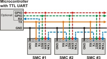 The Maestro boards using USB appear as two serial ports. One is the command port that communications with the Maestro processor. The other is a TTL port. This port can serve as simply a USB to TTL serial port converter to allow communications with other boards, even from another vendor. Another use of the TTL port is to daisy chain Pololu boards. I could attach the SMC boards in this manner and save two USB ports for other devices. These boards support this by having a TXIN pin that ANDs the TX signal from the connected board with the TX on the board.
Both of these controllers support a few different communications protocols. I use the one Pololu created and is available on some of their other products. The command details are different between the boards, but the basic command structure is the same. They call it their binary protocol, and the basic format follows:
0xAA, <device address>, <command>, <optional data>, <crc>
All the fields are single bytes except for the data field which is frequently 2 bytes to transmit 16-bit data. The returned data is only one or two bytes with no additional formatting. Note they provide for detecting errors in the message by using a CRC (cyclical redundancy check). This is probably not critical over USB but a TTL line might receive noise from motors, servos, and other devices. A CRC error sets a bit in the error register that can be read if the command is critical.
I wrote my own code, C++ of course, for the PC and converted it just now to the Raspberry Pi. The main change is the different serial port code needed by Linux and Windows. Pololu now provides Arduino source for the protocol making it easy to use these boards with that family of controller boards.
Wrap Up
The chassis, Pi, and these boards are now installed on the Wild Thumper chassis along with a pan and tilt controlled by servos. A safety LED is on when power is applied and flashes when the robot is actively controlling the system. A LiPo battery powers all but the Pi because I need to configure a battery eliminator circuit to provide five volts. I’m powering it temporarily using a USB battery pack.
A test program, cross compiled from my desktop, moves the robot forward, pivots left than right, and then reverses. The pan / tilt moves and the LED flashes. I originally used a web camera for vision processing but will switch to the Pi camera since it is better. The Neato lidar discussed in a previous article will soon find a place onboard, along with an accelerometer to detect possible rollovers.
I’m sure I could have done this using Pi daughter boards despite the challenges I mentioned earlier. There are trade-offs to both approaches that need to be considered when working on a project. But there is one final advantage to the external boards: they have a lot of twinkly LEDs.
Product photos from Pololu.
Filed under:
Arduino Hacks,
Raspberry Pi,
robots hacks