Posts with «adxl335» label

Arduino Pedometer Counts Your Steps

There’s a trend in corporate America that has employees wear a step counter — technically a pedometer — and compete in teams to see who can get the most number of steps. We wonder how many people attach the device to an electric drill and win the competition easily. However if you want to do your own measurements, [Ashish Choudhary] has plans for making a pedometer with an Arduino. The device isn’t tiny, but as you can see in the video below it seems to work.

For the extra size, you do get some features. For one, there is a 16×2 LCD display and an ADXL335 accelerometer, and you can probably imagine some other cool features for such a device.

The Arduino computes the magnitude of the acceleration, and if it exceeds a certain threshold it adds a step to the step count. Honestly, this is a fun project but it cries out for a more compact form factor. An ESP8266 for example could ditch the display and connect via WiFi to your phone. Then again, your phone can probably do the same job, as could not to mention many smartwatches. But those don’t have nearly as much geek cred as this project.

This is a little large for a hamster. On the other hand, there’s plenty you can do with the accelerometer after you’ve had enough fun counting steps.

Interfacing accelerometer with arduino uno

Interfacing accelerometer with arduino uno


Introduction:

In this post, we are going to interface accelerometer with arduino. Accelerometer is a sensor used for detecting motion or change in coordinates. We have three coordinates i.e X, Y and Z axis. It's a five-pin device out of which are for power supply Vcc and Ground. The output of the sensor is in analog.
This sensor required three analog pins. We can provide Vcc and ground directly from the analog pins.
So, we are using five analog pins. Three for axis and two for providing power to the module.

Components required:

  1. Arduino Uno
  2. ADXL335 (accelerometer)
  3. USB type B cable for interfacing with computer.
Connections:

Make connections as follows:

ADXL335                                    Arduino
Vcc                                               A0
X                                                  A1
Y                                                  A2
Z                                                  A3
Gnd                                              A4

The program is quite simple. We are using adc for reading the values of X, Y and Z axes. 
Also, the adc value  is in raw format means its value ranges from 0 to 1023.
No need to manipulate the raw adc value.


Once, we get the raw values of adc, we will fed it to serialprint function to check its output through serial monitor.

Application of accelerometer:

Used in smartphones for motion detection and orientation sensor. It found enormous application in
motion sensing game consoles. In case of robotics, we can use it for hand gesture based robot or to synthesize the hand gesture into voice.

Source code:

// these constants describe the pins. They won't change:
const int groundpin = A4;             // analog input pin 4 -- ground
const int powerpin = A0;              // analog input pin 5 -- voltage
const int xpin = A1;                  // x-axis of the accelerometer
const int ypin = A2;                  // y-axis
const int zpin = A3;                  // z-axis (only on 3-axis models)


void setup() {

  Serial.begin(9600);

  pinMode(groundpin, OUTPUT);
  pinMode(powerpin, OUTPUT);
  digitalWrite(groundpin, LOW);
  digitalWrite(powerpin, HIGH);
}

void loop() {
  Serial.print(analogRead(xpin));
  Serial.print("\t");
  Serial.print(analogRead(ypin));
  Serial.print("\t");
  Serial.print(analogRead(zpin));
  Serial.println();
  delay(100);
}


Output from serial monitor of arduino

Thanks for viewing this post.


Hackaday Prize Entry: Open Source FFT Spectrum Analyzer

Every machine has its own way of communicating with its operator. Some send status emails, some illuminate, but most of them vibrate and make noise. If it hums happily, that’s usually a good sign, but if it complains loudly, maintenance is overdue. [Ariel Quezada] wants to make sense of machine vibrations and draw conclusions about their overall mechanical condition from them. With his project, a 3-axis Open Source FFT Spectrum Analyzer he is not only entering the Hackaday Prize 2016 but also the highly contested field of acoustic defect recognition.

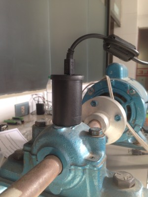
For the hardware side of the spectrum analyzer, [Ariel] equipped an Arduino Nano with an ADXL335 accelerometer, which is able to pick up vibrations within a frequency range of 0 to 1600 Hz on the X and Y axis. A film container, equipped with a strong magnet for easy installation, serves as an enclosure for the sensor. The firmware [Ariel] wrote is an efficient piece of code that samples the analog signals from the accelerometer in a free running loop at about 5000 Hz. It streams the digitized waveforms to a host computer over the serial port, where they are captured and stored by a Python script for further processing.

From there, another Python script filters the captured waveform, applies a window function, calculates the Fourier transform and plots the spectrum into a graph. With the analyzer up and running, [Ariel] went on testing the device on a large bearing of an arbitrary rotating machine he had access to. A series of tests that involved adding eccentric weights to the rotating shaft shows that the analyzer already makes it possible to discriminate between different grades of imbalance.

The HackadayPrize2016 is Sponsored by:

Filed under: The Hackaday Prize