Using an electroencephalography (EEG) headset and gyroscopic tracking, researchers have created a mind-controlled Tesla Model S.
Self-driving cars seem to be all the rage these days in technology circles, but, as part of Cal Hacks 3.0, researchers have instead figured out how to drive a car using brain waves. This hack takes the form of an EEG headset that translates brain signals into “stop” and “go” commands, with a head-mounted gyroscopic sensor used to tell the steering wheel how to turn.
A radio link using an Arduino transmits these signals to the car’s new physical controls. This takes the form of linear actuators for the brake and accelerator pedal, and a windshield wiper motor for the steering wheel.
There’s just something about wielding a laser pointer on a dark, foggy night. Watching the beam cut through the mist is fun – makes you feel a little Jedi-esque. If you can’t get enough of lasers and mist, you might want to check out this DIY “laser sky” effect projector.
The laser sky effect will probably remind you of other sci-fi movies – think of the “egg scene” from Alien. The effect is achieved by sweeping a laser beam in a plane through swirling smoke or mist. The laser highlights a cross section of the otherwise hidden air currents and makes for some trippy displays. The working principle of [Chris Guichet]’s projector is simplicity itself – an octagonal mirror spun by an old brushless fan motor and a laser pointer. But after a quick proof of concept build, he added the extras that took this from prototype to product. The little laser pointer was replaced with a 200mW laser module, the hexagonal mirror mount and case were 3D printed, and the mirrors were painstakingly aligned so the laser sweeps out a plane. An Arduino was added to control the motor and provide safety interlocks to make sure the laser fires only when the mirror is up to speed. The effect of the deep ruby red laser cutting through smoke is mesmerizing.
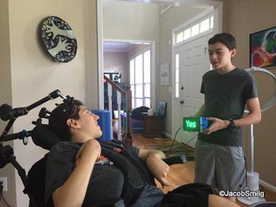
After an accident, Ethan Kadish was paralyzed. His friend, 14-year-old Jacob Smilg, came up with a simple device to help him communicate.
Several years ago, Kadish was struck by lightning, and lost control over his body. Communication with the world took the form of eye blinks for “yes” and “no,” which gave Smilg an idea for a revolutionary, Arduino Uno-based gadget that could help him communicate with people not familiar with this method.
It uses two pads, which Kadish can press with his head. When pressed, the device displays “yes” or “no” on a small LED screen. This allows him to have conversations in a more natural way, which, as seen in the video below around 4:00 it appears to make him very happy!
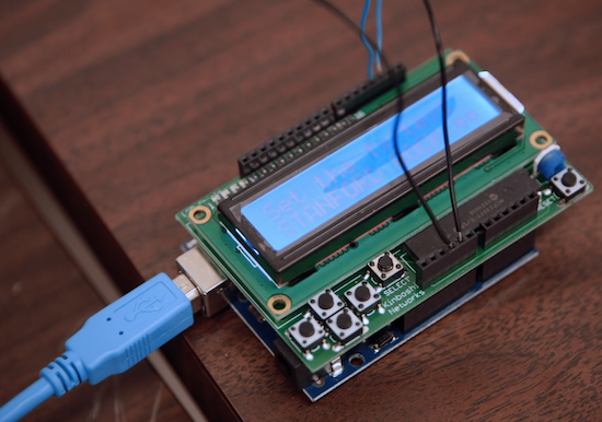
In order to convince his kids to stay in bed just a little longer, Maker Ralph Crutzen has created a “wakeup light” using an Arduino Mega and an RGB LED strip.
Those of us that have toddlers know that they can wake up very early. If you’d like to get some more sleep without leaving them unsupervised to dangerously play with your electronics and power tools, then a “wakeup light” could be a good solution.
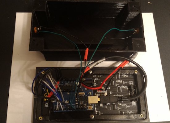
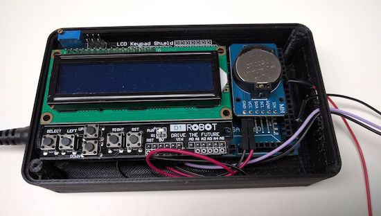
Crutzen’s system uses an Arduino Mega with a real-time clock to control a strip of LEDs, along with an LCD display to change settings. Besides a reminder to kids to “please stay in bed a few minutes longer,” perhaps a similar setup could be used as alternative alarm clock for adults as well.
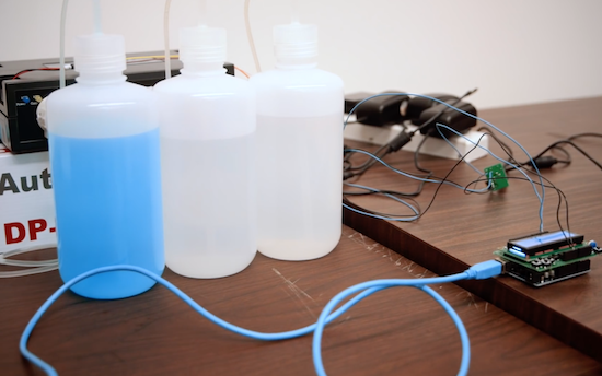
Stanford researchers led by post-doctoral fellow Nariman Farsad have built a machine that sends text messages using common chemicals.
If you’re building a project, and need to send a signal from one component to another, solutions generally involve wiring them together, or some sort of radio, perhaps Bluetooth or Wi-Fi. Farsad, however, has been working on something entirely different. His system uses commonly-available chemicals to turn a liquid, either basic or acidic, in sequence as a binary communication protocol.
But instead of zeros and ones, it sends pulses of acid (vinegar) or base (glass cleaner). The researchers type their desired message in a small computer, which sends a signal to a machine that pumps out the corresponding “bits” of chemicals. The liquids travel through plastic tubes to a small container that reads the solution’s pH. Changes in pH are then transmitted to a computer that deciphers the encoded message.
Once perfected, a messaging system like this could be used by devices inside of a human body or by tiny robots communicating with a chemical trail like ants. It can even leave secret messages that others wouldn’t even know to look for. Though still in its infancy, this method could open up an exciting array of possibilities!
Developed by a team of UC Berkeley students, Skintillates is a wearable technology that mimics tattoos.
When you think of temporary tattoos, you likely think of something that comes out of a gumball dispenser, or perhaps “art” that you got on a spring break trip. As interesting as those may be, Skintillates is taking things to the next level.
These “epidermal wearable interactive devices” can serve as everything from passive and active on-skin displays, to capacitive and resistive sensors for controlling gadgets, to strain gauges for posture detection.
Using several layers allows these designs to stick to the skin, integrate various electronics, and have visible art for others to see. Electronics can mean that the tattoos can integrate sensors, or perhaps even LEDs. In at least one case, these lights are programmed to flash along with the beat of music, driven by an Arduino hidden under the wearer’s clothing.
Just like the traditional temporary tattoos often worn by children and adults alike, Skintillates flex naturally with the user’s skin. Our simple fabrication technique also enables users to freely design and print with a full range of colors to create application-specific customized designs.
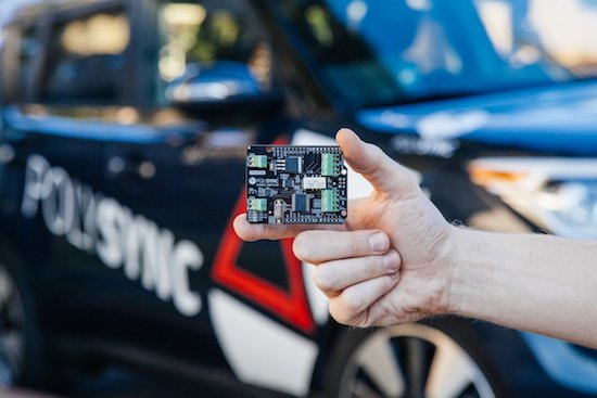
If you’re tired of waiting around to get an autonomous vehicle, PolySync’s Open Source Car Control Project (OSCC) development kit can be had for under $1000.
Autonomous cars are still in their infancy, and can cost upwards of $100,000. If you’re willing to do some of the work yourself—and trust a machine you modified to drive you around—PolySync has an Arduino-based kit (nearly) available to help you build your own.
You can pre-order a kit right now for $649, and you’ll have program each Arduino module yourself when you receive it. You’ll also need a 2014-or-later Kia Soul on which to install it, chosen for its combination of drive-by-wire controls as well as relatively low price. Keep in mind, however, the project is intended for R&D and off-road use only.
The OSCC Project is built around a number of individual modules that interoperate to create a fully controllable vehicle. These modules are built from Arduinos and Arduino shields designed specifically for interfacing with various vehicle components. Once these modules have been programmed with the accompanying firmware and installed into the vehicle, the vehicle is ready to receive control commands sent over a CAN bus from a computer running a control program.
It seems Power Wheels are like LEGO — they’re handed down from generation to generation. [Nicolas] received his brand-new Peg-Perego Montana Power Wheels in 1997 as a Christmas present. After sitting in a barn for a decade, and even being involved in a flood, it was time to give it to his godchildren, though not without some restoration and added features. His webpages have a very good write-up, just shy of including schematics, but you’ll find an abbreviated version below.
The starting point
Due to time and the flood, not only did it need a new paint job, and some plastic bits restored, but the hard plastic wheels had to be emptied of water, and the entire wiring harness needed replacing, as did some of the screws. Luckily the gearbox and motors needed only cleaning and new grease.
Whether it needed it or not, [Nicolas] wanted to add an Arduino Teensy 2.0++ as brains as he hadn’t seen anyone do that before and it also allowed him to brush up on his Arduino skills.
Arduino board and speedometer LCD display
He first made use of the Arduino for one new feature, a speedometer with a dash mounted Nokia 5110 LCD display. To measure the speed he used an infrared diode along with an NPN transistor, two LM324 op-amps and a few other parts. He even drew up with some very nice custom graphics for the LCD display.
He’d originally planned to add a variable accelerator by having the Arduino do PWM to a custom H-bridge, and even went a fair way toward making it, but even at 100% PWM the speed was too slow. With only a bad oscilloscope at the time for debugging, he abandoned the H-bridge for relays instead.
Lights
When it came to the lighting, [Nicolas] went all out with high intensity white and blue LEDs on custom circuit boards. He also had to do an exhaustive search online for light covers, but luckily there’s quite a bit out there for Power Wheels parts, though some he took from a Civic at a junkyard. [Nicolas] is in France and reading his experience in hunting for these parts gives an interesting look into the difficulties in buying things from the US when shipping costs can easily exceed parts cost. We can see why sometimes it’s simply not an option.
Another new feature was a dash mounted radio. That was followed by a new battery charger, a quantity of fuses to rival that in many cars, a lovingly done paint job and many labels and stickers that show just what a job of passion this was. We’re sure his godchildren will love their better-than-new Power Wheels.
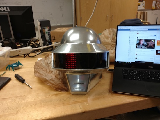
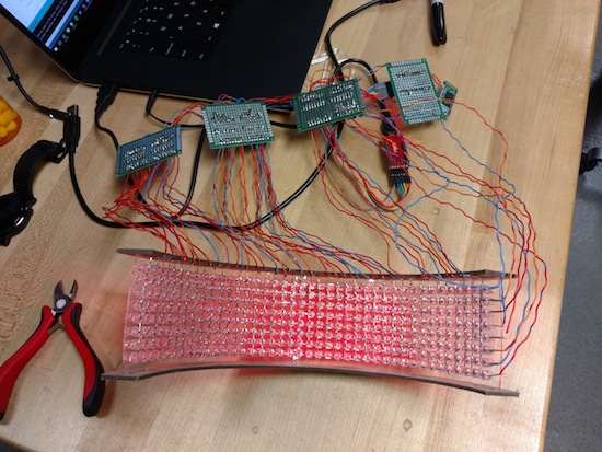
Though it’s been done before, this 3D-printed Thomas Bangalter helmet is absolutely amazing!
Daft Punk hasn’t toured in over a decade, but their music and general look seems to be becoming more and more popular. Perhaps this is due, in some small part, to the fact that Makers can now build a very good replica of their iconic helmets. Though the design for this helmet is available for download, looking at a design and building it are two different things.
In addition to printing and finishing this prop (no small task), redditor “CrazyElectrum” did quite a bit of soldering. Getting all the electronic components to “play nice” with each other certainly took a good amount of work as well!
The helmet consists of 326 LEDS with 10 programmed displays, all controlled via Bluetooth and a custom smartphone app. Meanwhile, the ears are equipped with a pair of WS2812B strips. CrazyElectrum originally employed an Arduino Uno for its brains, but later moved to a Pro Mini due to its smaller form factor, and used six 74HC595 8-bit serial to parallel shift registers.