Posts with «arduino» label

Arduino knight rider circuit using led bargraph

In this post, we are going to make knight rider circuit using led bargraph. Led graph, it consists of 10 leds.

Stuff required:

  1. Arduino uno
  2. LED bargraph
  3. 220 ohm resistor
  4. connecting wires
Connections:

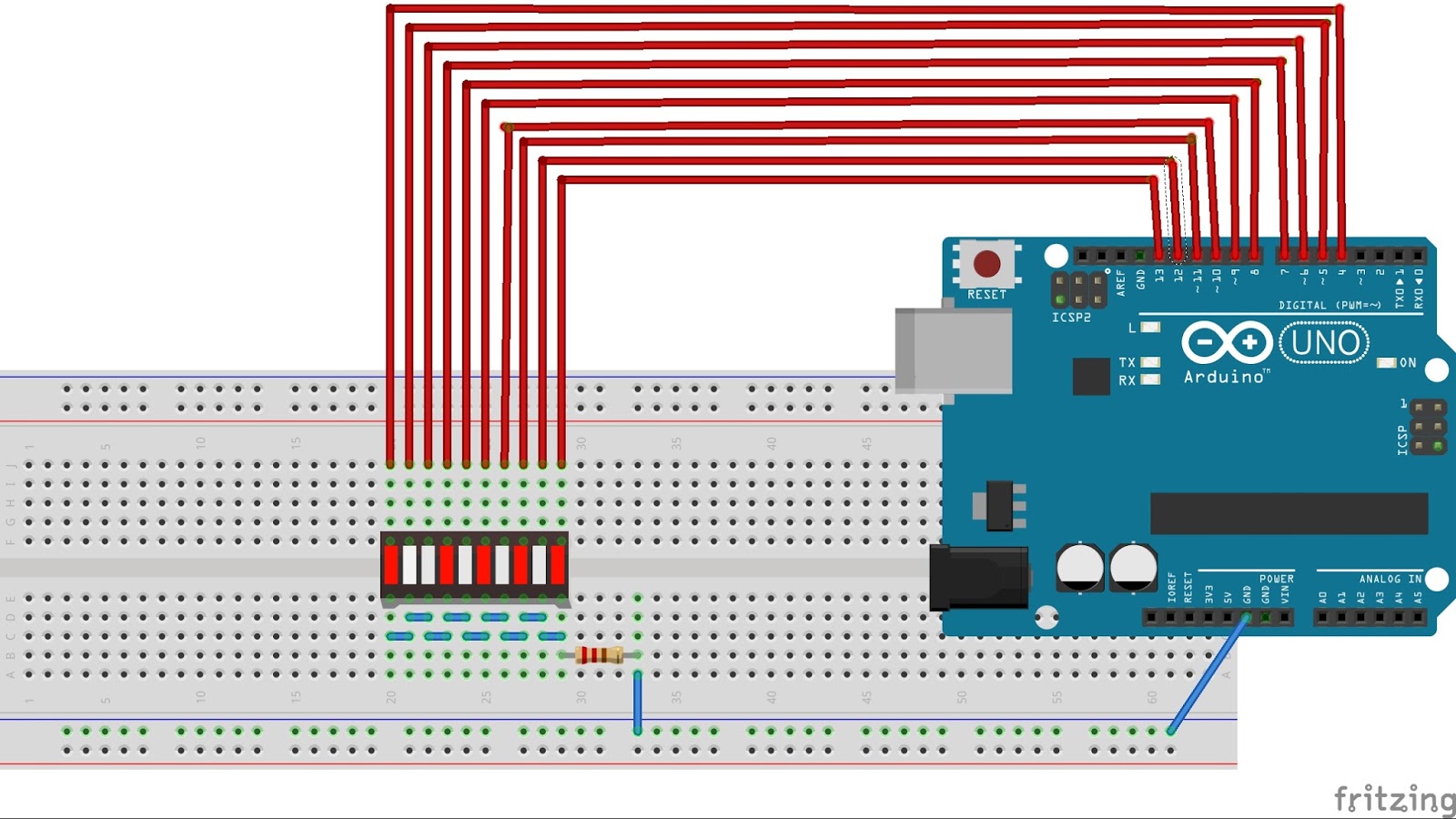
First of all, make connections as given in the diagram below:

connections
Source code:

Upload the code below to your arduino board

/* Code starts from here */

const int led[]={4,5,6,7,8,9,10,11,12,13},d=5;

void setup() {
  for(int i=0;i<10;i++)
    pinMode(led[i],OUTPUT);
}

void loop() {
  for(int i=0;i<10;i++)
    {
    digitalWrite(led[i],HIGH);
    delay(d);
    digitalWrite(led[i],LOW);
    }

  for(int j=0;j<8;j++)
    {
    digitalWrite(led[8-j],HIGH);
    delay(d);
    digitalWrite(led[8-j],LOW);
    }
}

/* Code ends here */

Hope, you had enjoyed this post. Thanks for reading this post.

Check out the video:


Stay tuned for more tutorials.


Make Your Own Arduino Header Pins

There are two kinds of people in the world (and, no, this isn’t a binary joke). People who love the Arduino, and people who hate it. If you’ve ever tried to use a standard prototype board to mount on an Arduino, you’ll know what kind of person you are. When you notice the pins aren’t on 0.1 inch centers, you might think, “What the heck were those idiots thinking!” Or, you might say, “How clever! This way the connectors are keyed to prevent mistakes.” From your choice of statement, we can deduce your feelings on the subject.

[Rssalnero] clearly said something different. We weren’t there, but we suspect it was: “Gee. I should 3D print a jig to bend headers to fit.” Actually, he apparently tried to do it by hand (we’ve tried it, too). The results are not usually very good.

He created two simple 3D printed jigs that let you bend an 8-pin header. The first jig bends the correct offset and the second helps you straighten out the ends again. You can see the result in the picture above.

[Rssalnero] notes that the second jig needed reinforcement, so it is made to take 8 pins to use as fulcrums. Probably doesn’t hurt to print the jigs fairly solid and using harder plastic like ABS or PETG, too. Even if you don’t have a 3D printer, this is about a 15 or 30 minute print on any sort of reasonable printer, so make a friend. Worst case, you could have one of the 3D printing vendors make it for you, or buy local.

We love little tool hacks like this. If you are too lazy to snap 8 pins off a 40 pin strip, maybe you’d like some help. If you’d rather go with a custom PC board, you might start here.


Filed under: Arduino Hacks, tool hacks

Lixie is a Nixie tube alternative

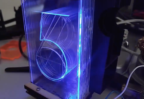
Using a series of etched acrylic panes, the “Lixie” display can show numbers in the style of a Nixie tube.

Nixie tubes are beautiful pieces of display hardware that are no longer in production, and are becoming harder and harder to find. They also generally require relatively high DC voltages to operate, making them difficult and potentially dangerous. Connor Nishijima, however, has come up with an alternative called the Lixie.

This laser-cut item employs etched panes of acrylic to reflect the light from WS2812B LEDs as required, revealing digits 0-9. Since the LEDs are RGB, different colors can be selected as desired.

Edge-lighting panes of acrylic etched with a design has been done for decades, but they’ve always been static information like an “EXIT” sign. If you stack multiple panes of acrylic (each with a unique design) and light them individually, you can change what design the user sees! This makes edge-lighting perfect for a numeric display! And since I love the look of Nixies, we’ll emulate the typography as well. At the end of the day, what I’ve made is a beautiful over-sized numeric display using WS2812Bs and a laser cut digit assembly!

You can find more about this “modernized Nixie tube” on Hackaday.io.

Arduino Blog 13 Dec 19:19

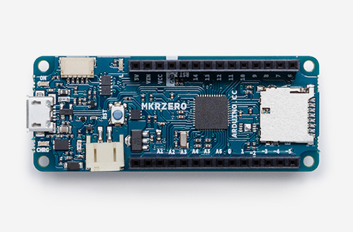
Meet the new MKRZero, the power of the Zero in a smaller board!

Say hello to the newest member of the Arduino family! The MKRZero–now available on our stores at the price of $21.90/€20.90 (+ tax)–shrinks the functionality of the Arduino Zero down into an Arduino MKR1000 form factor, making it a great educational tool for learning about 32-bit application development.

Like the Zero, the latest board is based on a Microchip SAM D21 ARM Cortex®-M0+ MCU. An integrated SD connector with dedicated SPI interfaces (SPI1) allows you to play with files without any extra hardware, while an analog converter enables you to monitor its battery voltage.

The MKRZero’s features in a nutshell:

  • small form factor
  • number crunching capability
  • low power consumption
  • integrated battery management
  • USB host
  • integrated SD management
  • programmable SPI, I2C and UART

Interested? You can explore the MKRZero in more detail, including its technical documentation, via the links below:

On the software side:

  • If you use the Arduino IDE, you will need to add the new Intel SAMD Core, selecting Tools menu, then Boards, and last Boards Manager on the Arduino Software (IDE).
  • If you use Arduino Web Editor, everything is already updated!

Watch out music makers, we’ve got some news for you! We have released two libraries for your enjoyment:

  • Arduino Sound library – a simple way to play and analyze audio data using Arduino on SAM D21-based boards.
  • I2S library – to use the I2S protocol on SAMD21-based boards. For those who don’t know, I2S (Inter-IC Sound) is an electrical serial bus interface standard for connecting digital audio devices.

Buy a brand new Arduino MKRZero now!

Join the discussion on the Arduino Forum!

Build an Arduino-powered, voice-activated clock

Using the MOVI voice recognizer and synthesizer Arduino shield, this DIY clock can respond to your querries.

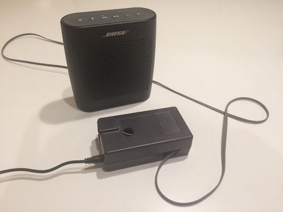
We’re all familiar with the various brands of voice assistants, but most of them require Internet access in order to do anything useful. This project, however, employs the MOVI shield by itself to respond to a user’s request for the time or date, and can even set a timer or initiate a countdown. The clock replies back in a nice robotic tone with the piece of information the user was asking for.

The voice-activated clock also features an Arduino Uno, an RTC module, a speaker that plugs into the MOVI’s headphone jack, and a power supply. Although an interesting build as is, much more functionality could be added to the system, allowing for a custom device to suit your needs!

You can learn more about the project on its page here!

More Blinky = More Better – The WS2812FX Library

The WS2812 is an amazing piece of technology. 30 years ago, high brightness LEDs didn’t even exist yet. Now, you can score RGB LEDs that even take all the hard work out of controlling and addressing them! But as ever, we can do better.

Riffing on the ever popular Adafruit NeoPixel library, [Harm] created the WS2812FX library. The library has a whole laundry list of effects to run on your blinkenlights – from the exciting Hyper Sparkle to the calming Breathe inspired by Apple devices. The fantastic thing about this library is that it can greatly shorten development time of your garden-variety blinkables – hook up your WS2812s, pick your effect, and you’re done.

[Harm]’s gone and done the hard yards, porting this to a bevy of platforms – testing it on the Arduino Nano, Uno, Micro and ESP8266. As a proof of concept, they’ve also put together a great demonstration of the software – building some cute and stylish Christmas decorations from wood, aluminium, and hacked up Christmas light housings. Combining it with an ESP8266 & an app, the effects can be controlled from a smartphone over WiFi. The assembly video on YouTube shows the build process, using screws and nails to create an attractive frame using aluminium sheet.

This project is a great example of how libraries and modern hardware allow us to stand on the shoulders of giants. It’s quicker than ever to build amazingly capable projects with more LEDs than ever. Over the years we’ve seen plenty great WS2812 projects, like this sunrise alarm clock or this portable rave staff.
As always, blink hard, or go home. Video after the break.


Filed under: Arduino Hacks, Holiday Hacks, led hacks

Make Etch A Sketch doodles on a VGA screen

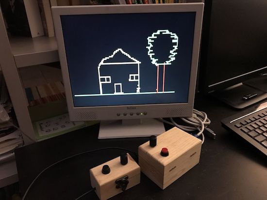
After building a Pong game using an Arduino Uno and a VGA monitor, Rob Cai realized this same setup could be used to make Etch A Sketch-style drawings.

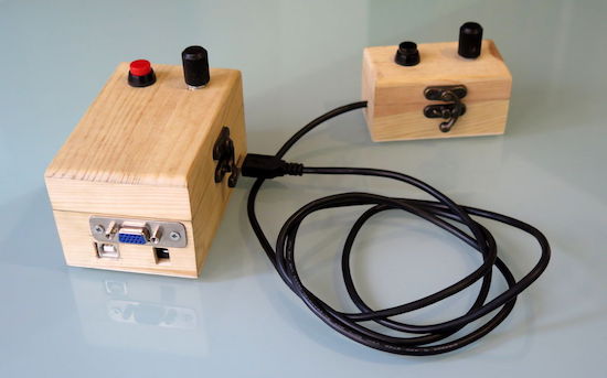
Control is surprisingly “Pong-compatible” with two boxes, each with a potentiometer and a button. One knob moves the cursor horizontally and the other vertically. Unlike an actual Etch A Sketch from your childhood, one button chooses the line color, while the other resets the screen (instead of shaking).

His system takes advantage of Sandro Maffiodo’s VGAx library, meaning it doesn’t need much more than a sacrificial VGA cable to draw a low-resolution picture on the display.

You can check out Cai’s Etch A Sketch on Instructables, where you’ll also find the project in its Pong form.

Arduino Clock Is HAL 1000

In the movie 2001: A Space Odyssey, HAL 9000 — the neurotic computer — had a birthday in 1992 (for some reason, in the book it is 1997). In the late 1960s, that date sounded impossibly far away, but now it seems like a distant memory. The only thing is, we are only now starting to get computers with voice I/O that are practical and even they are a far cry from HAL.

[GeraldF6] built an Arduino-based clock. That’s nothing new but thanks to a MOVI board (ok, shield), this clock has voice input and output as you can see in the video below. Unlike most modern speech-enabled devices, the MOVI board (and, thus, the clock, does not use an external server in the cloud or any remote processing at all. On the other hand, the speech quality isn’t what you might expect from any of the modern smartphone assistants that talk. We estimate it might be about 1/9 the power of the HAL 9000.

You might wonder what you have to say to a clock. You’ll see in the video you can do things like set and query timers. Unlike HAL, the device works like a Star Trek computer. You address it as Arduino. Then it beeps and you can speak a command. There’s also a real-time clock module.

Setting up the MOVI is simple:

 recognizer.init(); // Initialize MOVI (waits for it to boot)
 recognizer.callSign("Arduino"); // Train callsign Arduino (may take 20 seconds)
 recognizer.addSentence(F("What time is it ?")); // Add sentence 1
 recognizer.addSentence(F("What is the time ?")); // Add sentence 2
 recognizer.addSentence(F("What is the date ?")); // Add sentence 3
...

Then a call to recognizer.poll will return a numeric code for anything it hears. Here is a snippet:

// Get result from MOVI, 0 denotes nothing happened, negative values denote events (see docs)

 signed int res = recognizer.poll(); 

// Tell current time
 if (res==1 | res==2) { // Sentence 1 & 2
 if ( now.hour() > 12) 
 recognizer.say("It's " + String(now.hour()-12) + " " + ( now.minute() < 10 ? "O" : "" ) +
     String(now.minute()) + "P M" ); // Speak the time
...

Fairly easy.

HAL being a NASA project (USSC, not NASA, and HAL was a product of a lab at University of Illinois Urbana-Champaign – ed.) probably cost millions, but the MOVI board is $70-$90. It also isn’t likely to go crazy and try to kill you, so that’s another bonus. Maybe we’ll build one in a different casing. We recently talked about neural networks improving speech recognition and synthesis. This is a long way from that.


Filed under: Arduino Hacks, clock hacks

An Arduino laser pinball machine

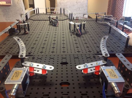
Pinball machines may seem like a good Maker project, but the mechanical components are quite involved. “Joesinstructables,” however, decided to take on this project on using an Erector Set, solenoids, and an Arduino board. In order to get around the challenge of using a heavy steel ball, he instead used a much lighter ping pong ball, sensed in the game by laser tripwires.

A number of solenoids propel the ball around and sound a service desk bell whenever a target is hit–one to three times depending on the difficulty level. Once the ball comes to rest in a target, a laser tripwire automatically triggers a solenoid to eject the ball, putting it back in play.

You can see more info on this build here, or even check out an earlier version for more inspiration!

Serial communication with arduino

In this post, we will learn how to serial communicate other device or arduino suing serial communication.

Introduction:

Serial communication (RS-232) is widely used communication for data transfer. It just uses three wires: Rx, Tx and GND

  In serial communication, 8/9 -bit is transferred through a single wire. The data frame is like this:

Start bit > Data fields (8 or 9 bit data) > Stop bit


Speed of data transfer is measured in terms of baud rate or bps:

Standard is: 9600 baud rate, none parity bit and one stop bit.
The baud rate should be same for both the devices. Any mismatch in the baud rate and the data will not be transmitted properly.
Bluetooth module (HC-05), Zigbee, GMS module, GPS module all these module uses serial communication. In fact, for communication between two microcontroller, we can use serial communication.

Connections:

Arduino                                                      Device
Tx            ===============>               Rx
Rx            ===============>               Tx
GND        ===============>               GND

For interfacing arduino with pc/ laptop, we need terminal software like bray's terminal. 

Just plug in the arduino in your pc/ laptop upload the program below and open terminal software.
Open comport in terminal sofware. The comport should be of arduino.

/* Program starts here */

void setup() {
Serial.begin(9600);   // starts serial communication @9600 bps
}

void loop() {
Serial.print("ARDUINO");   // serially print arduino
//Serial.println("ARDUINO");   // serially print arduino in new line

delay(1000);  // dealy of 1000ms
}

/* Program ends here */

Check this video: