Here at Hackaday we are big fans of the TV show, “How It’s Made”. It’s not much of a stretch to assume that, as somebody who is currently reading this site, you’ve probably seen it yourself. While it’s always interesting to see the behind the scenes process to create everyday products, one of the most fascinating aspects of the show is seeing how hard it is to make things. Seriously, it’s enough to make you wonder how companies are turning a profit on some of these products when you see just how much technology and manual work is required to produce them.
 That’s precisely the feeling we got when browsing through this absolutely incredible overview of how [HDC3] makes his maple syrup. If that’s not a sentence you ever thought you’d see on Hackaday, you aren’t alone. But this isn’t a rusty old pail hanging off of a tap, this is a high-tech automated system that’s capable of draining 100’s of gallons of sap from whole groves of trees. We’ll never look at a bottle of syrup in the store the same away again.
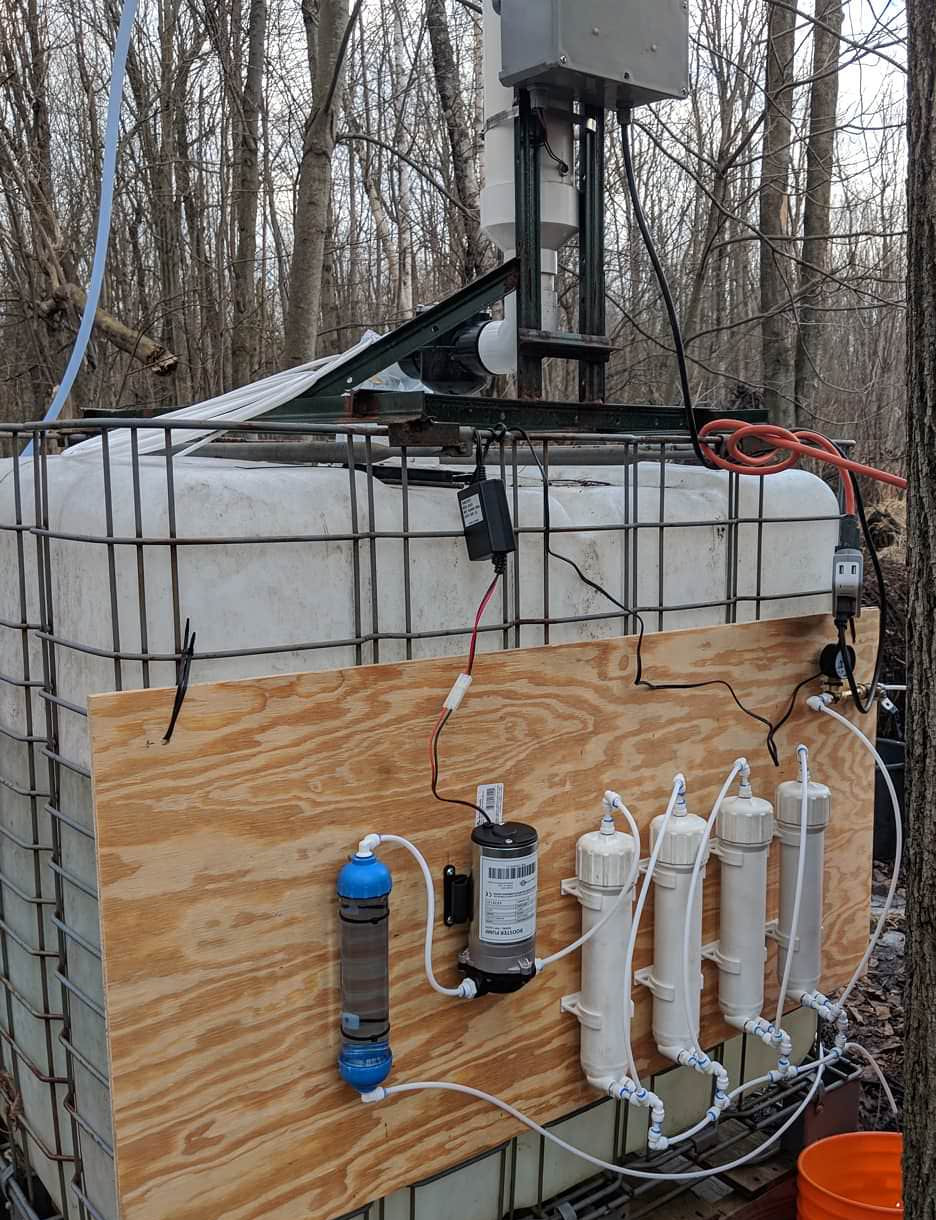
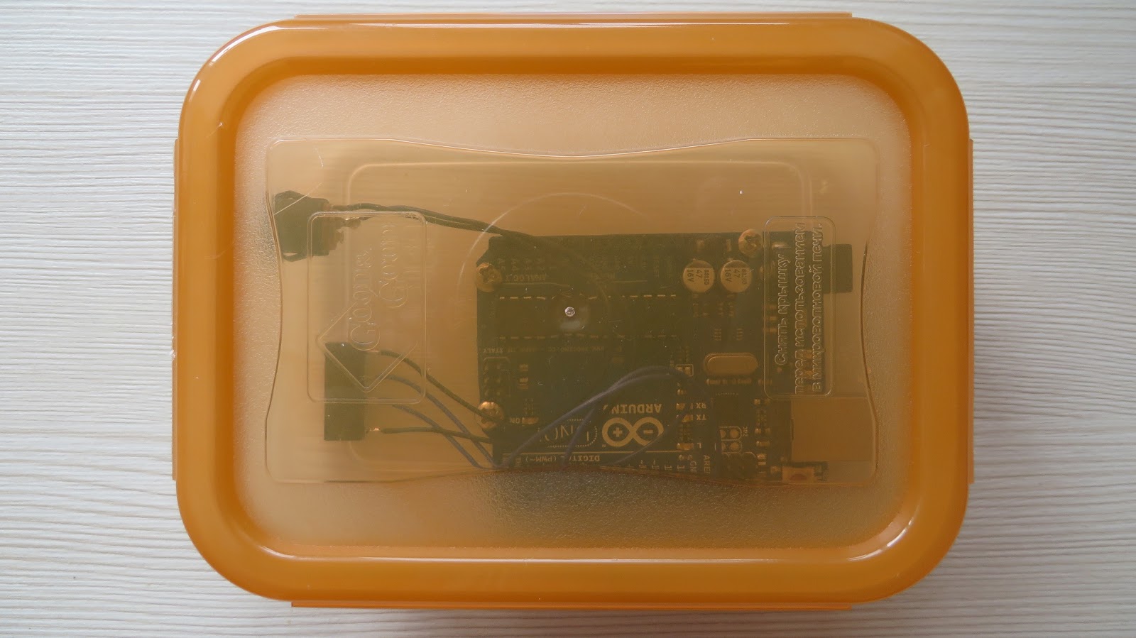
It all starts with hundreds of tiny taps that are drilled into the trees and connected to a network of flexible hoses. The plumbing arrangement is so complex that, in certain, areas high tension support wires are necessary to hold up the weight of the hoses and their sweet contents. The main hose leads to an Arduino-powered collection station which maintains a 100 kPa (29 inHg) vacuum throughout the entire system.
The sap is temporarily held in a 250 gallon container, but at this point it’s still just that: sap. It needs to be refined into something suitable for putting on your pancakes. The first step of that process utilizes a reverse osmosis filtration system to pull the water out of the sap and increase its sugar concentration. [HDC3] says the filtration system is built from eBay scores and parts from the home improvement store, and it certainly looks the part of something that would be under a kitchen sink. This system is able to increase the sugar concentration of the sap from around 2% as it comes out of the trees to 8%. But it’s still a far way off from being ready to use.
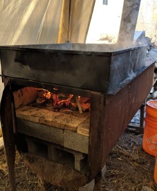 Interestingly enough, the last steps of the process are about as old-school as they come. The semi-concentrated sap is placed in a long low metal pan, and heated over a wood fire to drive off more of the water. This process continues until the sap is roughly 60% sugar, at which point it is filtered and moved into the house to finish boiling on the stove.
All told, the syrup is boiled for eight hours to bring its sugar content up to 66%. Even with the improvements [HDC3] has made to the system, he reveals that all this hard work only results in slightly more than a half-gallon of final syrup. Talk about dedication.
It probably comes as no surprise that this is the first time Hackaday has ever run a story about producing maple syrup. However we’ve seen a number of automated beer brewing systems that seem to have been tackled with similar zeal. There’s probably a conclusion to be drawn there about the average hacker’s diet, but that’s a bit outside our wheelhouse.
[via /r/DIY]